
International Research Journal of Engineering and Technology (IRJET) e-ISSN: 2395-0056
Volume: 11 Issue: 03 | Mar 2024 www.irjet.net p-ISSN: 2395-0072
International Research Journal of Engineering and Technology (IRJET) e-ISSN: 2395-0056
Volume: 11 Issue: 03 | Mar 2024 www.irjet.net p-ISSN: 2395-0072
Amit hipparagi1 , Mangesh A Deshmukh2 , Mohmmad sufiyan Rajapatel3
1,3Design Engineer, Tata Technologies Ltd, Pune 2Manager, Tata Technologies Ltd, Pune
Abstract - A system of servo control is EPS. This essay addresses the basic components of an electric power steering systemandoffersavalidjustificationforthedevelopmentand controller correction techniques, taking into account the controller's major technical index. The respective control technique of the electrically powered steering system is created in line with the performance requirements of the vehicle steering system, and the necessary software and hardware is created to implement this control strategy and regulateeachlinkinthevehiclesteeringprocess.Comparative studies are carried out on a vehicle outfitted with the produced EPS and the imported EPS, respectively, to confirm the viability of the control technique. The outcomes demonstratethatthegeneratedEPSperformssimilarlytothe importedEPS.ThedesignedEPScanbeemployedinlight-duty vehicles because it not only performs well but also has acceptable steering performance.
Key Words: ElectricpowersteeringSystem,ECUbuilding Fuzzification,fuzzilogic
An increasing number of active control systems, including electricpowersteering(EPS),activesuspension systems(ASS),andanti-lockbrakesystems(ABS),havebeen developed in an effort to further improve vehicle performance.Manyofthesesystemshavebeeninuseona commercial basis for almost forty years. An increasing numberofindividualcontrolsystemsarebeingusedbecause nosinglesystemcanbeeffectiveacrossthewholerangeof vehicle operating conditions. These systems are made for specific purposes, so interference between them and a complex systematiccontrol isinevitable, whichlimitsand degrades the performance of the vehicle. It is well recognizedthatthecoordinatedeffortsofmultiplevehicle controlsubsystemsaremostlyresponsibleforimprovingthe dynamicsofthevehicle.Asaresult,thereisapropensityto integrate the various subsystems in order to ensure and improve the functioning of thevehicle. Thishas become a researchfocusinthefieldofvehicledynamicscontrol.
The usage of electric power-assisted steering in automobile vehicles has increased significantly. Theoretically,therearetwotypes:electro-hydraulicpower steering(EHPS),whichutilizesanelectricmotortodrivea hydraulic pump, and electric power steering (EPS), which usestheelectricmotortodirectlyassistthesteeringaction (a pump similar to that used in conventional power
steering). WhileEPSis forecasttogrow dramaticallyover the next few years, EHPS penetration, which is presently estimatedatapproximately8%,isexpectedtostaysteady.It is projected that EPS, which presently has a 25% market share,willbestandardequipmentineverysecondcarsold inthenexttenyears.IncomparisontoEPS,theEHPSsystem hasadditionalpartssinceitalsoincludesahydraulicpump, a brushless DC (BLDC) electric motor, and the necessary electronic control unit (ECU). EHPS is preferable to conventional power steering because it can control and improvethehydraulicpumpdrive'senergyefficiency.The pump does not need to build up pressure if little or no steering is required. This cannot be done (or can only be done extremely expensively and laboriously) with a standard power steering system since the pump is driven directlybythecombustionengine.AnEPSnolongerhasa hydraulic system. The electric motor directly assists the steeringmotion.
Therearelowercostsbecausethehydraulicsystem isnotthere.Nevertheless,theriskisincreasedintheevent offailuresincetheelectricmotordirectlyaffectsthesteering column. This has delayed the implementation of these systemsandcreatedamarketopportunityforEHPS,which hasalowerriskoffailure.Nevertheless,thisriskhasbeen diminished by redundancy for crucial sub-components (similar to the aircraft industry) and thorough validation testing.
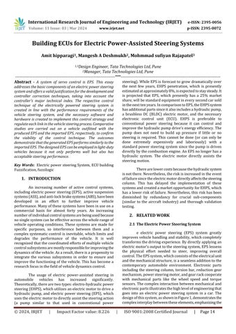
e electric power steering (EPS) system greatly improvesvehiclehandlingandstability,whichcompletely transformsthedrivingexperience.Bydirectlyapplyingan electricmotor'soutputtothesteeringsystem,EPSlessens the physical effort needed to steer, improving overall control.TheEPSsystem,whichconsistsoftheelectricalunit andthemechanicalstructure,isaseamlessadditiontothe contemporary automobile environment. Electronic parts including the steering column, torsion bar, reduction gear mechanism,powersteeringmotor,andgearrackcooperate with mechanical parts like the wheel speed and torque sensors.Thecomplexinteractionbetweenmechanicaland electronicpartsillustratesthehighlevelofengineeringthat goes into an electric power steering system in a car. The designofthissystem,asshowninFigure1,demonstratesthe complexinterplaybetweentheseelements,emphasizingthe
International Research Journal of Engineering and Technology (IRJET) e-ISSN: 2395-0056
seamless integration of mechanics and technology for the bestdrivingperformance.
3. THE DESIGN FOR THE HARDWARE OF THE CONTROLLER
3.1 Power Vary Circuit
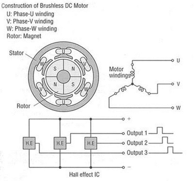
Theprimarycharacteristicsofthisbrushdcmotor are:ratedvoltageof12V,ratedcurrentof30A,andrated speedof1180RPM.Weemploydcpulsewidthmodulation (PWM)technologyforpowermotorcontrol.Themodulation frequency generated by the MCU in this system, which operatesonasetfrequencywidth,is21KHz.Thefollowing arethemainbenefitsofPWMspeed:(1)themaincircuitis
simple, requiring fewer power components; (2) due to its highswitchfrequency,requiringonlythefilteringactionof the armature inductance, we can obtain the smooth dc current, and its speed adjusting performance is good; (3) switchingdevicesworkonlyinswitchcondition,consuming littlepowerinthemaincircuit,andthedevicesarehighly efficient..Powervariescircuitshowninfigure2.
2 . PowerVariesCircuit
3.2 The Overall Framework For Hardware Circuit
The microcontroller, power circuit, signal processing circuit, dc motor power driving module, fault diagnosisanddisplaymodule,speedsensor,torquesensor, engineignitionsignal,accessprocessingcircuitforcurrent andcurrentsensor,etc.arethemainmodulesthatmakeup thehardwarecircuitoftheelectricpowersteeringsystem. Figure 3 below depicts the EPS system hardware's logical architecture.
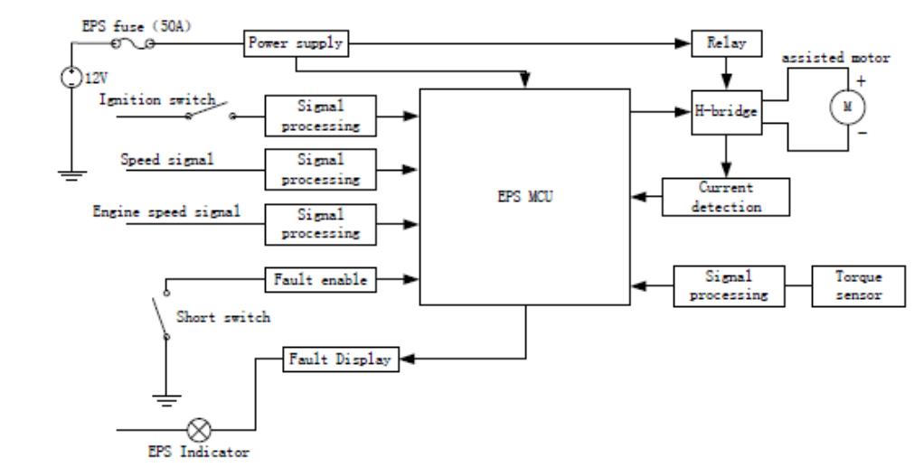
Figure 3 . CompositiondiagramforEPSControlSystem
Thehardwaredesignexhibitsafewthings:(1)we employtwodistinctinputroadsforthecircuittoincrease dependability.Thenumerationchipautomaticallyrecords thepulsenumberononeroute.TwoHSIportsontheMCU finish the job in the other route; setting a hardware watchdog to prohibit PWM output; and focusing on
Volume: 11 Issue: 03 | Mar 2024 www.irjet.net p-ISSN: 2395-0072 © 2024, IRJET | Impact Factor value: 8.226 | ISO 9001:2008 Certified Journal | Page15
International Research Journal of Engineering and Technology (IRJET) e-ISSN: 2395-0056
Volume: 11 Issue: 03 | Mar 2024 www.irjet.net p-ISSN: 2395-0072
electromagnetic compatibility and strong and weak electricityseparationwhiledesigningthePCB.(4)Theheat dissipationofthepowercomponentsneedstobenotedin thestructure'slayout.
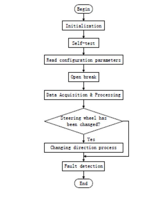
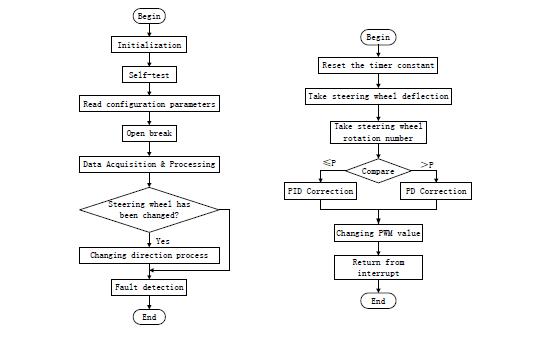
Using the modular design concept and the C programming language. It can be separated into the main programmeandtheinterruptserviceproceduredepending, interrupt input reflecting steering wheel rotation on its functions. The primary programme is for data acquisition and processing to achieve the high sampling rate requirements. Several control tasks, including serial communicationsinformation,settingthewatchdogtimerto anumber,timingPWMoutput,andtimerfaultdiagnosis,are completed via interrupts. The primary programme flow chart is shown in Figure 5(a). The algorithm for PID correction and PWM output interrupt service is shown in Figure 5(b). The software design additionally takes the followingactionstoguaranteethesystem'sdependabilityon theanti-interferenceaspects:
(1)Digitalfilter:toaverage-filterthedatagathered to guard against pulse interference. This entails sorting a continuoussampleofalimitednumberofdata,eliminating thetwolargestandsmallest,andthenaveragetheremaining data.Moreover,usedifferentialidentificationtoaccountfor thevolumeofdata.
(2)Many"RST"directivesthatallowPCpointersto pointtotheprogram'sbeginningat2080Hareencodedin the routines. In addition, all programme modules have multiple"NOP"instructionsaddedinadvanceofthecrucial test,jump,andcallinstructions.
(3)Microcontrollersoftwarewatchdogfunctionis also utilised in addition to hardware watchdog. (4) To ascertainiftheoperatingstateisnormal,itisnecessaryto conductreal-timetestsonthemaincomponents,significant parameters (such as battery voltage, motor current, etc.), andsignificantstorageunits.(5)TowritetheEPROMwith thefundamentalsystemsettings.
3.1. WorkingAlgorithm
International Research Journal of Engineering and Technology (IRJET) e-ISSN: 2395-0056
Volume: 11 Issue: 03 | Mar 2024 www.irjet.net p-ISSN: 2395-0072
Fuzzy logic controllers find their niche in applications where the mathematical model of a system is excessively intricate or when there exists a nonlinear relationshipamongvariables.Theterm"fuzzy"denotesan imperfectrepresentationofnumbers,capturingnuancesthat classicalbinarylogicmightoverlook.Employingafuzzylogic controller becomes advantageous when either the system lacksaprecisemathematicalmodel,ortheavailablemodelis toocomplextoyieldpracticalresults.Thisapproachproves particularlyvaluableinscenarioswheresystemperformance improvementorsimplifiedimplementationisdesired.
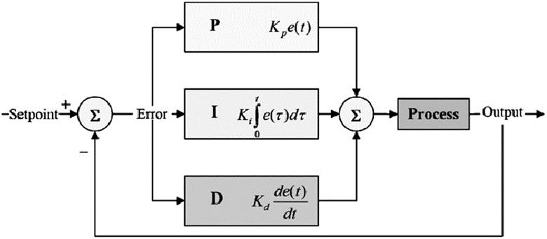
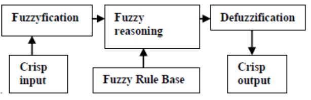
Despite its utility, fuzzy logic control necessitates behavioral information or a predefined solution for the system.Itoperatesontheprinciplesofnaturallanguageand leverages the expertise of domain experts. The fuzzy logic model emerges as a potent instrument for swiftly and effectivelyhandlingimprecisionandnonlinearity[2].Inthe realmoffuzzylogiccontrol,Figure4illustratesatypicalfuzzy logiccontroller,showcasingtheseamlessexecutionofthree essential tasks: fuzzification, fuzzy reasoning, and defuzzification. This integrated process facilitates the translationofvagueandimpreciseinformationintoawelldefinedandactionableoutput,makingfuzzylogiccontrollers’ invaluabletoolsfornavigatingcomplex,real-worldsystems
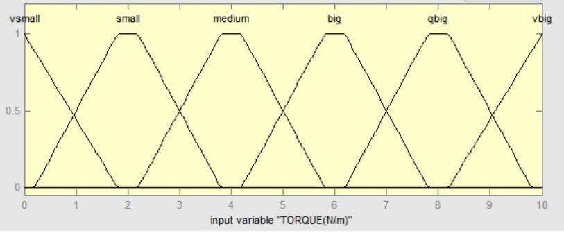
In the intricate process of fuzzy logic control, the pristine input undergoes a transformation into fuzzified inputscharacterizedbyfuzzylinguisticsandacorresponding Degree of Membership (DOM). These fuzzy inputs, represented by various fuzzy language sets such as VBIG, QBIG,BIG,MEDIUM,SMALL,andVSMALL,playapivotalrole inresolvinginputtorquecomplexities.Eachsetpossessesa
distinct degree of membership, contributing to a nuanced understanding of input properties. Similar to velocity settings, fuzzy settings generate a dynamic spectrum adjustable from ZERO to VFAST, QFAST, FAST, MEDIUM, SLOW,andVSLOW.Thisadaptabilityempowersthesystem to dynamically respond to changing conditions, accommodatingadiverserangeofscenarios.
Exploringthetheoreticalunderpinnings,afuzzyset canbeexpressedasA=x,(x)|Xxx,whereAisthefuzzyset,xis thecrispinput,(x)isthemembershipfunction,andXisthe universalset.Inourexample,torqueandvelocitydefinethe universal set boundaries, within which subsets are constructed using the fuzzy language sets. This systematic breakdownfacilitatesacomprehensiveanalysis,enhancing theunderstandingofinputcharacteristicsandtheirbroader implications.
Tofurtherelucidatetheseconcepts,Figure5serves as a visual aid, illustrating the seamless integration of trapezoidalandtriangularmembershipfunctionsforinput and output parameters. These graphical representations bridge thegapbetween abstract principles andreal-world applicationsinthefieldoffuzzylogicandcontrolsystems, providingatangibleillustrationofthediscussedtheoretical concepts. This visual approach aids in conveying complex ideas, making the theoretical foundations more accessible andapplicableinpracticalscenarios.
Withintheintricaterealmofalgorithmicdecisionmaking,fuzzyreasoningemergesasacrucialandnuanced step, offering a means to navigate the complexities of impreciseoruncertainknowledge.Thissophisticatedmethod takestheformoffuzzyrules,oftenexpressedwithIF-THEN statements,providingaframeworktocapturetheintricate nuances inherent in real-world scenarios. Fuzzy rules constitute the bedrock of fuzzy reasoning, and their formulationinvolvestheamalgamationofextensivedomain expertiseandpracticalexperienceofthesystem'sexpert.
Thearchitectureoffuzzyrulesisacarefullycrafted interplay of theoretical knowledge and hands-on control experience, as exemplified by the organized structure of Table I. This table serves as a comprehensive repository,
International Research Journal of Engineering and Technology (IRJET) e-ISSN: 2395-0056
Volume: 11 Issue: 03 | Mar 2024 www.irjet.net p-ISSN: 2395-0072
encapsulating language variables and their corresponding fuzzy rules, all distilled from authentic control scenarios. Each rule encapsulates the expert's tacit knowledge, transformingitintoasetofstructuredinstructionsthatguide thealgorithminmakingnuanceddecisions.
Therichnessofthefuzzyrulearchitecturenotonly contributestothealgorithm'sflexibilitybutalsounderscores thesymbioticrelationshipbetweenthedesigner'sexperience andthealgorithm'sprowessinnavigatingintricatedecision spaces.Theserules,expressedinawell-organizedmanner, serveasabridgebetweentheoreticalconstructsandpractical applications. They embody the collective wisdom derived fromreal-worldchallenges,providingthealgorithmwitha robustfoundationforeffectivedecision-making.
Furthermore, thestructuredpresentationof fuzzy controlrulesinTableIatteststotheintegrationoftheoretical knowledgeandpracticalcontrolexperience.Itshowcasesthe depthofunderstandingrequiredtodistillcomplexreal-world situationsintoasetofrulesthatanalgorithmcanutilizefor decision-making.Themutualenrichmentbetweenthesystem designer'sexpertiseandthealgorithm'sadaptabilityensures that the decision-making process is not only theoretically sound but also finely tuned to address the intricacies of dynamicandunpredictableenvironments.Inessence,fuzzy reasoning,asembodiedintheserules,standsasatestament tothefusionofhumanexpertiseandalgorithmicprecisionin thepursuitofeffectivedecision-makingincomplexdomains.
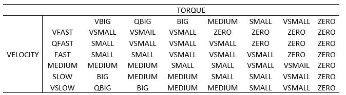
Thedutycyclevalueforthediscretesetsofvelocity andtorquefortheaidmotorispresentedintheabovetable. The assist motor is regulated by pulse-width modulation. Torquevelocityequalsdutycycle.Thefollowingrelationis usedtocalculatethedegreeofmembership(DOM)forthis aggregate.Torque=min[velocity(x)],dutycycle(x)].
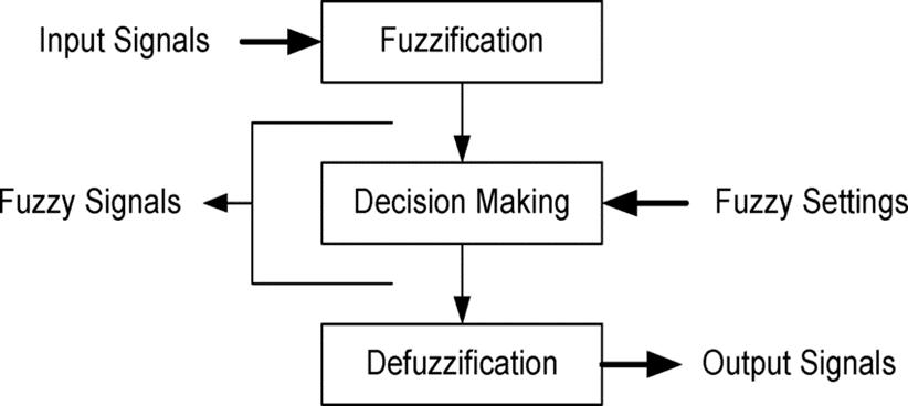
In this transformative phase, the previously nebulous languages seamlessly transition into a state of utmost clarity through the meticulous application of a weightedaverageapproachfordefuzzification.Thisintricate processculminatesina crispoutput,representedbyCrisp output=f(x),with(x)denotingtheDegreeofMembership (DOM)valuecorrespondingtothecrispinputx.Thejudicious implementation of the weighted average approach places precisionattheforefront,ensuringnotonlyaccuracybutalso arefinedanddistinctlyclearoutcome.Thesophisticationof thismethodologyliesinitsabilitytogenerateanoutputthat isnotonlyprecisebutalsotransparent,therebyenhancing theinterpretabilityofthesystem'sresponse.
The systematic refinement of fuzzy languages involvesathoughtfulconsiderationoflinguisticvariablesand their associated membership functions. Through this nuanced defuzzification process, the system navigates a multidimensional space of linguistic terms, allocating appropriateweightstodifferentregionsbasedonthedegree of membership. This intricate precision ensures that the resultingoutputnotonlyfaithfullyrepresentstheinputdata butalsooptimallycapturestheunderlyingpatterns,fostering arobustandreliabledecision-makingmechanism.
To vividly demonstrate the effectiveness of this approach, a test input is presented and comprehensively illustrated as a flow chart in Figure 6. This visual representationservesasanavigationalguide,offeringastepby-stepunderstandingofthecontrolmethodandfacilitating anintuitivecomprehensionofthesystem'sbehavior.
Furthermore, the adaptability of the weighted average approach is a notable feature, allowing for finetuning and customization based on specific application requirements.Thisadaptability,coupledwiththeinherent precision of the method, positions it as a versatile tool in various fields, including control systems, artificial intelligence,anddecisionsupportsystems.Delvingdeeper intotheintricatelayersofthismethodology,itseleganceis not only rooted in theoretical foundations but also in its practicalimplicationsforsolvingreal-worldproblems.The methodologyemergesasapowerfulandversatilesolution,
International Research Journal of Engineering and Technology (IRJET) e-ISSN: 2395-0056
Volume: 11 Issue: 03 | Mar 2024 www.irjet.net p-ISSN: 2395-0072
bridgingthegapbetweentheoryandpracticalapplicationin complexdecision-makingscenarios.
Select a reasonable framework for the fuzzy controller:
Selectingasuitableframeworkforafuzzycontroller markstheinitialphaseinitsdevelopment.Thiscrucialstep involvesmakinginformeddecisionsaboutthestructureof the controller, beginning with the identification and definition of input and output variables. The careful determination of these variables serves as a fundamental prerequisite before delving into the specifics of the controller'sarchitecture.
In the process of designing a fuzzy controller, the selectionofanappropriateframeworkisakintosettingthe stageforitssubsequentfunctionality.Theframeworkactsas ascaffoldinguponwhichtheintricatenetworkoffuzzylogic, rules,anddecision-makingprocesseswillbebuilt.Therefore, the success of the fuzzy controller isinherently tied tothe thoughtful consideration and definition of its input and outputvariables.
Thechoiceofinputvariablesinvolvesidentifyingthe keyparametersorfactorsthatwillinfluencethecontroller's decision-making.Thesevariablesencapsulatetheessential aspectsofthesystemundercontrol,providingthenecessary inputforthefuzzylogictoprocess.Ontheotherhand,output variablesrepresentthedesiredoutcomesorcontrolactions thatthefuzzycontrollerwillgeneratebasedontheprocessed inputinformation.
By establishinga clear understanding of theinput andoutputvariables,systemdesignerslaythegroundwork forformulatingtherulesandlogicthatwillgovernthefuzzy controller'sbehavior.Thissystematicapproachensuresthat thefuzzycontrolleristailoredtothespecificcharacteristics and requirements of the targeted system, enhancing its adaptability and effectiveness in managing complex and dynamicenvironments.
Insummary,themeticulousprocessofchoosinga frameworkforafuzzycontrollerinvolvesastrategicfocuson defininginputandoutputvariables.Thisfoundationalstep setsthestageforthesubsequentdevelopmentofthefuzzy logic, rules, and decision-making processes, ultimately contributingtothecontroller'sabilitytonavigateandcontrol complexsystems.
The foundational elements of a fuzzy controller reside in its fuzzy control rules. The process of generating theserulesisacriticalaspectofcreatinganeffectivefuzzy logic system, and it involves careful consideration of key
factors related to specified performance requirements. Typically, a set of fuzzy rules is formulated, taking into accountfourcrucialperformanceconcerns,eachcontributing to the overall efficiency and reliability of the fuzzy logic system:
Thisperformanceconcernemphasizestheneedforthe fuzzy controller to react swiftly when presented with significanterrorsinthesystem.Rapidresponseensuresthat the controller can quickly adjust its output to bring the system back to the desired state, mitigating the impact of largeerrorsonsystemperformance.
Overshooting, where the system response extends beyond the desired setpoint, can lead to instability and undesirable outcomes. Fuzzy control rules are crafted to preventorminimizeovershooting,ensuringacontrolledand stableresponsetochangesintheinputorsetpoint.
Oscillations in the system's response can introduce instability and hinder smooth operation. Fuzzy rules are designedtosuppressoscillations,providingamechanismto dampenoreliminateundesirablefluctuationsinthesystem output. This contributes to the overall stability and predictabilityofthefuzzycontroller.
Achieving zero steady state error is a critical performancegoal,particularlyinsystemsweremaintaininga precisesetpointisessential.Fuzzycontrolrulesaretailored to ensure that, over time, the systemsettlesat the desired setpoint with minimal or zero deviation, enhancing the controller'saccuracyandlong-termperformance.
By incorporating these performance concerns into the generation of fuzzy control rules, system designers aim to createafuzzylogicsystemthatnotonlyrespondseffectively to dynamic changes but also operates with stability, precision, and minimal error. The careful consideration of thesefactorsunderscorestheadaptabilityandreliabilityof fuzzycontrollersacrossawiderangeofapplications.
Establish a control table and decide on fuzzification and defuzzification strategies:
Whendevelopingafuzzycontrolsystem,allfaults anderrorratesmustfirstbeconvertedfromcrispinputsto fuzzyinputs.Thecrispoutputforthecontrol'sexecutionwill thereafterbecreatedfromthefuzzysetUofcontrolrates.
International Research Journal of Engineering and Technology (IRJET) e-ISSN: 2395-0056
Volume: 11 Issue: 03 | Mar 2024 www.irjet.net p-ISSN: 2395-0072
Establish the fuzzy controller's parameters:
The phrase "basic universe of discourse of the quantizedvariables"referstotheusefulrangeoferrorand errorrateinacontrolsystem.Itisnecessarytoascertainthe universe of discourse for each input and output while creating a particular fuzzy controller. The A/D and D/A converters in the fuzzy controller's voltage and current rangewillbespecifiedbythesecontrolneeds..Nonetheless, thefuzzylogiccontroller'sstructureincludesscalingunits, whichletthecontrollermagnifytheinputsandoutputstoa desiredrange.
Whendesigningandimplementingelectronicpower steering(EPS)systems,packagingtechnologyisessentialto achievingthebestpossibleperformance,dependability,and spaceefficiency.ThepackagingprocessforEPSentailsthe fusionofmultiplepartsandsubsystemsintoasturdy,small unit.Thefollowingareimportantfeaturesoftheelectronic powersteeringsystems'packagingtechnology:
1. Compact Design: Compared to conventional hydraulic systems,electronicpowersteeringsystemsaremadetobe smaller.Thepackagingtechnologyaimstoreducetheamount of space needed, making it easier to integrate into contemporarycars,wherespaceisfrequentlyatapremium. Theremovaloflargehydraulicpartsmakesthisdesignmore compact.
2.IntegrationofElectronicComponents:Sensors,controllers, and actuators are just a few examples of the electronic components that must be integrated into the packaging of EPS.Together,thesepartsmeasuresteeringinput,process data,andgivethedriverthehelptheyneed.Theseelectronic componentsareplacedinsidethecarcorrectlyandarewellprotectedthankstoefficientpackaging.
3.HeatDissipation:Duringoperation,electroniccomponents produceheat,andefficientpackagingtechnologytakescare of this requirement. To keep electronic components from overheatingandtoprolongtheirlifespan,thedesignincludes heat sinks, cooling fans, and other thermal management strategies.
4.VibrationandShockResistance:Duringoperation,vehicles encounter varying degrees of vibration and shocks. EPS packaging technology considers these dynamic conditions andincorporatesdesignsandmaterialsthatabsorbshockto prevent damage or malfunction to delicate electronic components.
5. Environmental Protection: Electronic power steering systems are subjected to a variety of challenging environmental factors, such as temperature fluctuations, dust,andmoisture.Long-termdependabilityisensuredby packaging technology, which uses weather-resistant
materials,sealedenclosures,andprotectivecoatingstoshield thecomponentsfromexternalinfluences.
6.ElectromagneticCompatibility(EMC):Toavoidinterfering with other vehicle electronics, electronic power steering systemsarepackagedwithelectromagneticcompatibilityin mind. In order to control electromagnetic emissions and shield the system from outside interference, shielding techniquesareused.
7. Serviceability: The ease of maintenance and repair is anotheraspectofpackagingtechnology.Inordertominimize downtimeduringmaintenance,componentsthatmayneedto be replaced or serviced, like sensors or electronic control units,arepositionedanddesignedwithaccessibilityinmind.
8.CostEffectiveness:Bymaximizingtheuseofresourcesand production techniques, efficient packaging helps to lower overall manufacturing costs. Mass production, component standardization,andmodulardesignsthatcanbemodifiedto fitvariousvehiclemodelsarealltakenintoaccount.
The controllerand electric power steeringsystem have undergone extensive testing and continuous development to deliver a high level of precision and responsivenessfordrivers.Thetactilesensationtransmitted through the steering wheel enhances control, allowing driverstoachieveprecisemaneuverswithease.Thesystem's impactonpowerdeliveryisequallyremarkable,contributing to a smooth and dynamic ride across various driving conditions.
As we approach the final stages of refining the software, our primary objective is to guarantee peak responsiveness and optimal performance. Leveraging advanceddiagnostictools,weareconductingthoroughtests to identify and rectify any potential issues. A meticulous debuggingprocessisbeingemployedtoaddressanyfaults, ensuring that the electric power steering system not only meetsbutexceedsthemoststringentrequirementsforuser satisfaction,safety,anddependability.
Thecommitmenttoachievingsuperiorperformance is reflected in the comprehensive testing protocols and ongoing development efforts. By focusing on refining the software, we aim to fine-tune every aspect of the electric power steering system to provide drivers with an unparalleled driving experience. The emphasis on user satisfaction extends beyond mere functionality, encompassing the creation of a driving environment that instillsconfidenceandreliability.
Inadheringtorigorousqualitystandards,wearenot only meeting industry benchmarks but pushing the boundaries to set new standards for excellence. The integration of advanced diagnostics and meticulous
International Research Journal of Engineering and Technology (IRJET) e-ISSN: 2395-0056
Volume: 11 Issue: 03 | Mar 2024 www.irjet.net p-ISSN: 2395-0072
debugging procedures underscores our dedication to deliveringaproductthatnotonlyperformsexceptionallybut also stands out in terms of safety, reliability, and user satisfaction.
Asweapproachthefinal stagesofthisrefinement process, our goal is not only to meet expectations but to surpass them, ensuring that the electric power steering systemsetsanewstandardforexcellenceintheautomotive industry. Through continuous testing, development, and a commitment to quality, we are confident that drivers will experiencealevelofcontrolandperformancethatexceeds eventhemostdiscerningexpectations.
References –
[1] NakayamaT,SudaE.Thepresentandfutureofelectric powersteering.IntJofVehicledesign1994;15:243–254.
[2]YasuoShimizu ,Toshitakekawai.DevelopmentofelectricpowerSteering.SAE91UU14.
[3] Badawy A,Bolourchi F,Gaut S. E•Steer TMsystemredefines steeri ng technology. Automotioe Engineering,1997
1U5(9):15-18.
[4]J.Kim,J.Song,Controllogicforanelectricpowersteering systemusingassistmotor,Mechatronics12,2002.
[5] O. Moseler, R. Isermann, “Application of Model-Based FaultDetectiontoaBrushlessDCMotor”,IEEETransactions OnIndustrialElectronics,2000.
[6]O.Moseler,R.Isermann,“Model-BasedFaultDetection for a Brushless DC Motor Using Parameter Estimation“, IEEE,1998.
[7]R.Isermann,Model-BasedFaultDetectionandDiagnosisStatus and Applications, International Federation of AutomaticControl,v.29no.1,pp.71-85,2005.
[8]R.McCann,“VariableEffortSteeringforVehicleStability EnhancementUsinganElectricPowerSteeringSystem”,SAE, 2000.
[9]Y.Lee,"AStudyonDevelopmentofanElectronicControl Unit and a Fault Detection Algorithm for a Motor Driven SteeringColumn",HanyangUniversity,1998.
[10]A.T.Zaremba,M.K.Liubakka,R.M.Stuntz, Control and Steering Feel Issues in the Design of an Electric Power Steering System, Proceedings of the American Control Conference,1998
[11]Shibahata,Y.,Irie,N.,Itoh,H.,andNakamura,K.,“The Development of an Experimental Four-Wheel Steering
Vehicle”,SocietyofAutomotiveEngineersTransactions,No. 860623,pp.862-869,1985.
[12]Sato,H.,Hirota,A.,Yanagisawa,H.andFukushima,T., “DynamicCharacteristicofaWholeWheelSteeringVehicle withYawVelocityFeedbackRearWheelSteering”,I.Mech.E. 124/83,RoadVehicleHandling,pp.147-156,1983.
[13] Szosland, A., “Fuzzy Logic Approach to Four-Wheel SteeringofMotorVehicle”,Int.J.ofVehicleDesign,Vol.24, No.4,pp.350-359,2000.
[14]Li,H.X.,andGatland,H.B.,“EnhancedMethodsofFuzzy LogicControl”,IEEETrans.Syst.,Man,Cybern.,pp.331–336, 1995.
[15]BingxinMa,YongfuWang,GangChen,Event-triggered type-2 fuzzy-based sliding mode control for steer-by-wire systems,Mechatronics,Volume82,2022,102704,ISSN09574158,https://doi.org/10.1016/j.mechatronics.2021.102704.
[16]Zhang, Shaoyun& Wang,Yi.(2015). StudyofElectric PowerSteeringSystem.10.2991/csic-15.2015.77.