
International Research Journal of Engineering and Technology (IRJET) e-ISSN: 2395-0056
Volume: 11 Issue: 02 | Feb 2024 www.irjet.net p-ISSN: 2395-0072
International Research Journal of Engineering and Technology (IRJET) e-ISSN: 2395-0056
Volume: 11 Issue: 02 | Feb 2024 www.irjet.net p-ISSN: 2395-0072
J. Sheeba
Ebenezer1, Shahnawaz Ahmed2
Kiran R. Govindappa
3 ,
Hamed Mabkhut Salim Al-Breiki
4
1,2,3Lecturer, Civil and Architectural Section, Engineering Department, University of Technology and Applied Sciences, Salalah, Oman
4 Student, Civil and Architectural Section, Engineering Department, University of Technology and Applied Sciences, Salalah, Oman ***
Abstract:
Structuraldesignistheprocessofinvestigatingabuilding's stiffness, strength, and stability. The primary goal of structuralanalysisanddesignistoconstructastructurethat can withstand all applied loads without failing for the specified life. Several steps are involved in the structural design process, including load computation, analysis, member design, and specifics. The traditional structural analysis method is fraught with difficulties and timeconsuming calculations. Excel software was used because fastsoftwareisusednowadaystocompleteanalysesinan efficient manner. To facilitate structural analysis, an excel sheetwithasimpleuserinterfaceiscreatedthatcanbeused byalmostanyone.Excelisdesignedtotakeaslittleinputas possiblewhileproducingasmuchoutputaspossible.
KeyWords: computationofloads,structuralanalysis,Excel software.
1. INTRODUCTION
1.1 General
Astructureinthecontextofcivilengineeringisanetworkof elementsheldtogetherbyconnectionstobeartheweightof externalloads.Thegoalofstructuralanalysisistopredict howastructurewillbehaveinresponsetoarbitraryloads thathavebeenspecifiedinadvance.Duringthepreliminary stage of structural design, the potential external load of a structure is assessed, and the size of the structure's interconnectedpartsisdeterminedbasedontheestimated loads. Structural analysis can be used to determine the relationship between a predicted external load on a structural member and the structure's corresponding produced internal stresses and displacements that occur withinthememberwhenitisinservice.Thisisnecessaryto ensurethatthestructuralmembersmeetthestandardsof thelocalbuildingcodeandthespecificationsoftheareain which the structure is located in terms of both safety and use.
The aim of the investigation is to analyse single storey residentialbuildingmanuallyandusingExcel
Thestudyincludesthefollowing:
Toknowtheimportanceofcomputationofloads
To analyse single storey residential building manuallyandusingExcel.
Sachin Tattimani., and Sri P.I Cholappanavar (2022), in thisstudytheanalysisanddesignofRCstructuresusingFEM based software package needs basic knowledge of that software.Thisprojectfocusesoncreatinganexcelsheetwith a simple user interface for analysing and designing RC structureswithoutanypriorsoftwareknowledge.Thisexcel sheetonlyconsidersgravityloads.Thesheetdefinesgridsin the X and Y directions. The user can specify the distance betweengrids.Thissheetspecifiesthedesignofthefooting andcolumn.
Nitin Tiwari, Rashmi Sakalle (2019), in this work, the EXCEL spreadsheet software was utilized to analyze and calculatethe rebarofvariousRCelementssuchasbeams, columns, and slabs. Five different types of EXCEL spreadsheetswerecalculatedinthisprojecteffort:simply supported beam, cantilever beam, short column and long column, one way and two-way slab. We used several compression member properties in this study, including effective span, nominal cover, and effective length. Aside fromtheincorporationofnumerousattributes,theRCparts haveundergonevariouschecks.ThesourceisRCCcodeIS 456:2000.
Akhil Deshbhratar, Ankita Madavi, Akanksha Meshram, Nirali Thakur, Milind Kumbhare, Neha Arukia (2022), thisstudycarriedoutastudytodesignvariouscomponents using excel and VBA software. The manual calculation methodisused.Itresultsinatime-consumingandlaborious
International Research Journal of Engineering and Technology (IRJET) e-ISSN: 2395-0056
Volume: 11 Issue: 02 | Feb 2024 www.irjet.net p-ISSN: 2395-0072
processofobtaininganalysisresultsforVBA-createddesign sheets.AVBAsoftwarehasbeendevelopedtoretrievethe analysis results in MS-Excel, completely automating the designprocessandreducingmanualintervention.
R. Rajasekaran (2018),inthisworkManualbeamdesign and analysis for even a small structureis time consuming andlaborious.Theuseofsophisticated designsoftware is expensive and requires a high level of software expertise. Thispaperdiscussesthecreationofasimpletoolthatusesa spreadsheettoanalyseanddesignbeamsforsmallbuildings. The structural beam layout, beam grouping, and loading diagramsareall done manuallyinthe first step. Based on this, a spreadsheet in Excel was created to calculate the bendingmomentandshearforce.Anotherspreadsheetis created for the analysis of design moments and reinforcements.Asampleanalysisanddesignarepresented, withasatisfactoryresult.Thecomplexityofbeamanalysis anddesignusingaspreadsheettoolisreduced.
Uziak, Jacek & Gandure, Jerekias & Martin, L.D. (2011), thispaperdescribeshowanExcelspreadsheetcanbeused as an educational tool for beam bending calculations. It discussesthebenefitsofusingspreadsheetsinengineering education. It also describes the spreadsheet for beam calculations that employs Macaulay's method. The spreadsheetcanbeusedforstaticallydeterminedaswellas indeterminatebeams.Itcomputesreactions(bothforcesand moments),shearforce,bendingmoment,anddeflectionsfor any of four common beam end-fixing conditions (simply supported, cantilever, propped, and built-in). The user specifies the dimensions of the beam, the loads, and their location.Thespreadsheetisdesignedtobeuser-friendlyand operatesasamenu-drivenprogramme
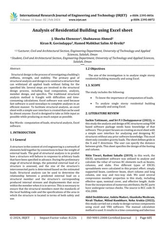
Thefollowingflowchartshowninfigure1,showsthe flowoftheproject.
This study demonstrates how to use excel, a programmeorsoftwarethatcancalculatereaction,shear force,andbendingmomentvaluesforspecifiedloadsand beamspans.Excelsheetsaredesignsheetsthathavean inbuilt cell-based structure and a simple boundary that aresimpletouseevenforinexperiencedusers.Itaidsin thecalculationofloadsinslabsandbeamsandisusedfor beamanalysisinasingle-storyresidentialbuildingusing theMSEXCEL
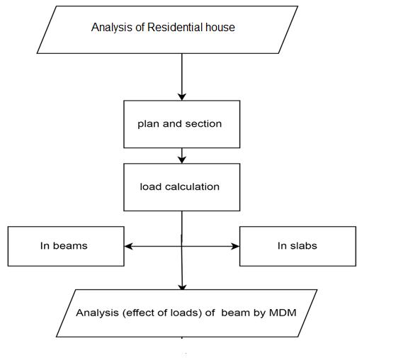
2showstheplanviewandsectionAAviewofa singlestoreyresidentialbuilding
-1: Flowchart
-2: PlanandsectionA-A
International Research Journal of Engineering and Technology (IRJET) e-ISSN: 2395-0056
Volume: 11 Issue: 02 | Feb 2024 www.irjet.net p-ISSN: 2395-0072
Load calculation for Slabs
Table – 1: CalculationofloadforBedroomslab
Table – 3: Calculationofloadforhallslab
Table – 2: Calculationofloadforkitchenslab
Table – 4: Calculationofloadfortoilet/storeslab toilet
Inthisstudy,thecalculationofloadforbedroomslab, kitchenslab,hallslabandtoiletareshownintables1,2,3 and4.Thespanwastakenandoveralldepthoftheslabs were calculated and ultimate loads were found for all slabs.
International Research Journal of Engineering and Technology (IRJET) e-ISSN: 2395-0056
Volume: 11 Issue: 02 | Feb 2024 www.irjet.net p-ISSN: 2395-0072
Table –7: CalculationofloadforbeamC1-B1
Load calculation for Beams
Table – 5: CalculationofloadforbeamB3-C3
Beam B3-C3
d=span/20
kN/m
Table –8: CalculationofloadforbeamB2-C2
Table –6: CalculationofloadforbeamA3-B3
Beam A3-B3
d=span/20
load on beam 234.86kN
Table –9: CalculationofloadforbeamA2`-B2 ` Beam A2`-B2` d=span/20 460mm span 9200 9 h=d+cover+10+20/2 505mm
b=h/1.5 336.7
International Research Journal of Engineering and Technology (IRJET) e-ISSN: 2395-0056
Table –10: CalculationofloadforbeamA1-B
BeamA1-B1
d=span/20 460mm
span 9200 9
h=d+cover+10+20/2 505mm
b=h/1.5 336.7mm
D.L=B/1000*H/1000 4.25kN/m
W=1.35DL 5.74kN/m
W*span 51.64kN/m
totalloadonbeam 315.52kN
Table –11: CalculationofloadforbeamC1-C2
BeamC1-C2
d=span/20
b=h/1.5 200mm
D.L=B/1000*H/1000 1.50kN/m
W=1.35DL 2.03kN/m W*span 6.08kN/m totalloadonbeam 6.08kN
Table –12: CalculationofloadforbeamA1-A2`
BeamA1-A2`
d=span/20 235mm
span 4700 4.5
h=d+cover+10+20/2 300mm
b=h/1.5 200mm
D.L=B/1000*H/1000 1.50kN/m
W=1.35DL 2.03kN/m
W*span 9.11kN/m
BeamC2-C3
d=span/20
b=h/1.5 200mm
D.L=B/1000*H/1000
Table –13: CalculationofloadforbeamC2-C3
BeamA1-A2`
d=span/20 235mm
b=h/1.5
D.L=B/1000*H/1000 1.50kN/m
W=1.35DL 2.03kN/m W*span 9.11kN/m totalloadonbeam 9.11kN
Table –14: CalculationofloadforbeamA2`-A3
BeamA2`-A3
d=span/20 140 mm span 2800 2.6
h=d+cover+10+20/2 300 mm
b=h/1.5 200 mm
D.L=B/1000*H/1000 1.50 kN/m W=1.35DL 2.03 kN/m
kN/m
Volume: 11 Issue: 02 | Feb 2024 www.irjet.net p-ISSN: 2395-0072 © 2024, IRJET | Impact Factor value: 8.226 | ISO 9001:2008
International Research Journal of Engineering and Technology (IRJET) e-ISSN: 2395-0056
Volume: 11 Issue: 02 | Feb 2024 www.irjet.net p-ISSN: 2395-0072
Table –15: CalculationofloadforbeamB2`-B3
D.L=B/1000*H/1000
Table –16: CalculationofloadforbeamB1-B2
Beam B1-B2
d=span/20
Table –17: CalculationofloadforbeamB2-B2`
BeamB2-B2`
In this study, the calculation of load for beams is shown in tables 5 - 17.The spanwastakenandoverall depth of the beams were calculated and ultimate loads werefoundforallbeams.
Beam B1-B2
d=span/20 160mm span 3200 3
h=d+cover+10+20/2
b=h/1.5
mm
D.L=B/1000*H/1000 1.50kN/m
W=1.35DL 2.03kN/m
6.08kN/m
MOMENT DISTRIBUTION METHOD
In1930,HardyCrossdevelopedandformallyreportedthe momentdistributionmethodforbeamandframeanalysis. Althoughthismethod,liketheslope-deflectionmethod,is adeformationmethod,itisanapproximatemethodthat does not require solving simultaneous equations. The number of subsequent approximations or iterations determinesthedegreeofaccuracyoftheresultsobtained bythemomentdistributionapproach.
The approach for analysing indeterminate beams using themomentdistributionmethodissummarisedbelow:
ProcedureoftheMomentDistributionMethodtoanalyze indeterminatebeamsisasfollows
• Determine the fixed-end moments of members, assumingthejointsarerestrainedagainstrotation.
• Determine the distribution factor for each element connectedatthejoint.
• Calculate and distribute the unbalanced moment at eachjointtotheendsofmembersconnectedatthatjoint.
International Research Journal of Engineering and Technology (IRJET) e-ISSN: 2395-0056
Volume: 11 Issue: 02 | Feb 2024 www.irjet.net p-ISSN: 2395-0072
• Transfer one-half of the distributed moment to the othermembers'endpoints.
•Addorsubtractthesesubsequentmoments(acquired in stages three and four) from the original fixed-end moments.
• Apply the determined endmoments to the provided structure'sjoints.
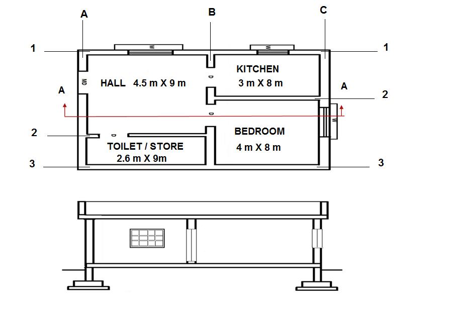
•Drawafree-bodydiagramofeachspanofthesupplied beam,displayingtheloadsandmomentsproducedusing themomentdistributionmethodatthejoints.
• Determine the support reactionsfor each span. Calculateanddrawshearingforceandbendingmoment diagramsforeachspan.
• Combine the figures in step 9 to create one bending momentandoneshearingforcediagramfortheprovided beam.
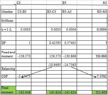
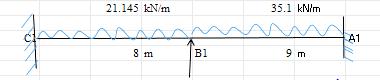
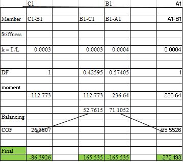
FixedendmomentforBeamsisshownintables18to21 calculatedbytheMomentDistributionMethod
International Research Journal of Engineering and Technology (IRJET) e-ISSN: 2395-0056
Volume: 11 Issue: 02 | Feb 2024 www.irjet.net p-ISSN: 2395-0072
Table –21: FixedendmomentforbeamA1-A2’-A3
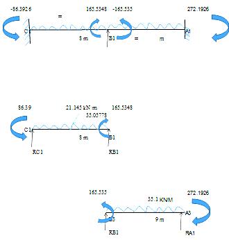
ReactionsforBeamsupportsareshownfrom22 to25calculatedbytheMomentDistribution Method.
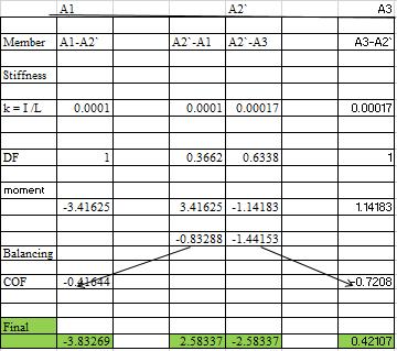
Table –22: SupportreactionforbeamC3-B3-A3
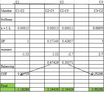
Table –23: SupportreactionforbeamC1-C2-C3
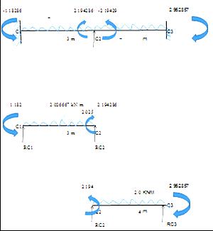
Table –24: SupportreactionforbeamC1-B1-A1
2024, IRJET | Impact Factor value: 8.226 | ISO 9001:2008
International Research Journal of Engineering and Technology (IRJET) e-ISSN: 2395-0056
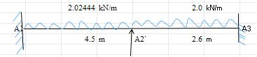
Table –25: SupportreactionforbeamA1-A2`-A3
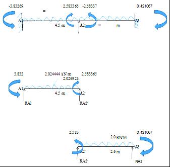
Table –26: Shearforceandbendingmomentdiagramfor beam C3-B3-A3
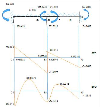
Table –27: Shearforceandbendingmomentdiagramfor beamC1-C2-C3
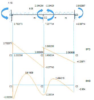
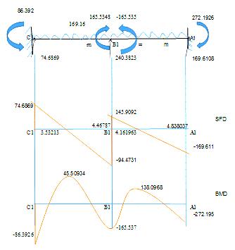
Table –28: Shearforceandbendingmomentdiagramfor beamC1-B1-A1
Volume: 11 Issue: 02 | Feb 2024 www.irjet.net p-ISSN: 2395-0072 © 2024, IRJET | Impact Factor value: 8.226 | ISO 9001:2008
International Research Journal of Engineering and Technology (IRJET) e-ISSN: 2395-0056
Volume: 11 Issue: 02 | Feb 2024 www.irjet.net p-ISSN: 2395-0072
Table –29: Shearforceandbendingmomentdiagramfor beamA1-A2`-A3
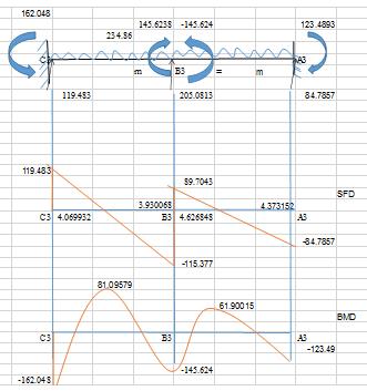
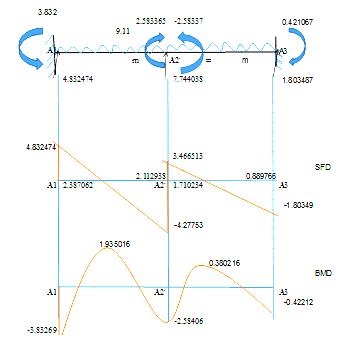
Shearforceandbendingmomentdiagramsareshownfrom 23to29.
Inthisstudy,anexcelsheetwasusedtostudyasingle-story residential building. It was discovered that processing in Excel is significantly more accurate and faster than processingbyhand;manycasescanbecompletedfasterby simply modifying the formula and the provided data in a shortperiodoftime.
WhileusinganExcelsheet,wasabletoimprovetheconcept andefficiencyofstructuralanalysis.
Paperwork was reduced and time was saved by using a computerized application. This increased efficiency and decreasedworkload.
[1] Sachin Tattimani., and Sri P.I Cholappanavar 2022 “Developing an individual excel sheet for design and analysis of beam and slab” International Journal for ResearchinAppliedScience&EngineeringTechnology (IJRASET)ISSN:2321-9653;ICValue:45.98;SJImpact Factor:7.538Volume10IssueIXSep2022.
[2] Tiwari, Nitin & Sakalle, Rashmi & Katare, Aman & Sharma,Manjeet&Shrivastava,Mayank&Khan,Mohd& Khan,Altamish&Gholap,Prajjwal.(2019).Automated Excel Sheets for Various RC Elements. 6. 2321-9653. 10.22214/ijraset.2018.11095.
[3] Akhil Deshbhratar, Ankita Madavi , Akanksha Meshram , Nirali Thakur , Milind Kumbhare , Neha Arukia, Use of Ms-Excel Sheets to Design Various Parameter of RCC Structure Review
[4] R.Rajasekaran,Analysisanddesignofbeamsusingspread sheet tool, International Journal of Management, Technology And Engineering Volume 8, Issue VI, JUNE/2018 ISSN NO : 2249-7455
[5] Uziak,Jacek&Gandure,Jerekias&Martin,L.D..(2011). Application of Spreadsheet in Beam Bending Calculations. IEEE AFRICON Conference. 12. 1-5. 10.1109/AFRCON.2011.6071988.