
Optimisation of weld size in single-sided groove butt joint
Sandeep Chowdhry1
1 Engineering Consultancy & Training Chandigarh, India
Abstract - The welding parameters influence the static strength of the butt weld joint used in the mechanical structures. It is essential to make correct-size welds, as an oversized weld is very costly and may not have good strength. It wastes welding consumables and may cause other fabrication problems, including excessive distortion. This study aims to use an appropriate optimisation method and finite element analysis model to develop a mathematical model to predict the required weld size. The results show that half-fraction factorial design is an appropriate optimisation method. The increase in applied load and safety factor leads to an increase in the required weld size. The lower tensile strength electrode leads to a bigger weld size. The developed mathematical model predicted the size of weld needed for a single-sided groove buttjointfortherangeoftheusedparameters.
Key Words: butt weld, optimisation, finite element analysis,weldsize,single-sidedgroovebuttjoint
1. INTRODUCTION
Abuttjointisthemostaccessibleweldingjointtoperform (next to the fillet weld). It is high strength with complete fusionandsomewhatlesssusceptibletocontamination. It is easy to inspect for distortion, easy to machine after weldingandapplicabletoavarietyofmetals.Itisexcellent for continuous linear or circumferential welds. Filler material strength, base material strength, and weld geometries, such as weld size, are essential factors in evaluating static strength [1]. The study [3] developed an appropriate method for predicting the ultimate tensile strength of partially penetrated groove welds and proposed design equations. The study [4] developed expressions for predicting the ultimate load and deformation capacities in the fillet welds. The study [5] showsthatafiniteelementanalysis(FEA)modelcouldbe developedwhoseestimationsforloadcarryingcapacityof butt-welded joints agree with the experiment results. The above studies indicate that the requirement of the weld size in single-sided groove butt weld may vary with differentcombinationsofappliedload,thefactorofsafety andelectrodematerialstrength.
Therefore, this study's main aim is 1) To select an appropriate optimisation method to refine the weld size; 2) To use FEA model to find the effect of applied tensile load on the weld size; 3) To use FEA model to find the
effect of factor of safety on the weld size; 4) To use FEA modeltofindtheeffectofelectrodetensilestrengthonthe weld size 5) To develop a mathematical model to predict therequiredweldsize.Thisstudyaimstocontributetoan understanding of using an appropriate optimisation methodtoenhancetheweldsize.Inaddition,itwillhelpin understanding the effect of appliedload, safety factor and electrode tensile strength on the single-sided butt joint weldsize.
2 STATIC JOINT DESIGN
Tosatisfytheweldingcriteria[1],alloysteelisselectedas thebasematerialoftheplatestobebuttwelded.Thebase materialhasaminimumyieldstrength of620MPa(<690 MPa)andabasematerialplatethicknessof6mm(>3mm). Electrode filler material strength mismatch m in welds is the ratio of filler material yield strength to the base material's yield strength. Based on this ratio, if m < 1, the case is called under-matching [2]. The study [5] recommendedamismatchratioofm<=0.7forthetesting ofthebuttweldjoints.Therefore,inthisstudy,electrodes E60 and E70 are selected as the electrode filler material yieldstrengthsare458.5MPaand479.9MPa,respectively. As a result, the mismatch ratio is 0.7 and 0.77, respectively.
2.1 Specimen geometry
Aspecimenofalloysteelmaterialwithdimensionsof400 mmx37mmx6mm,asshowninFig.1,wasusedforFEA. The FEA model was built as an assembly using mate constraintsontwoplatesofsize200mmx37mmx6mm. An alloy steel has a yield strength of 620 MPa and an ultimatetensilestrengthof723.8MPa.
11 Issue: 02 | February 2024 www.irjet.net

Fig -1: Dimensioneddrawingofthespecimen
2.2 Equipment
The study used SolidWorks CAM, Microsoft Excel, and Minitab2023software.
2.3 Specimen Preparation
The specimen part file was created as per the study [5] usingSolidWorks2023software.
2.4 Welding
The default software setting of the single-sided groove butt joint was applied to both half plates of the specimen toformabuttjoint.
3. DESIGN PARAMETERS
3.1 Parameters, Levels and Responses
Table 1 shows the level settings of the welding parameters,suchasload,safetyfactor,electrodeandweld size.Therequiredweldsizewasselectedastheresponse. Therangeofweldingoperationparameterswaschosenas per the American welding code [1], and initial FEA trial runswereperformedusingSolidWorkssoftware.
TABLE-1:LEVELSETTINGSOFLOAD,SAFETYFACTOR,ELECTRODE ANDWELDSIZEFORREQUIREDWELDSIZEASRESPONSEVARIABLE
To determine whether there is a linear or non-linear relationship between the load, safety factor, electrode, weld size and the required weld size, a null hypothesis (H0)isthatthereisalinearrelationshipbetweentheinput and response variables. An alternative hypothesis (H1) is that there is no linear relationship between the input and output variables. As a result, a half-fraction factorial designisused.
3.2 Half-Fraction Factorial Design
The study used Minitab 2023 software to create a randomised run order for the experiment involving four process parameters with low-level and high-level settings of the input variables load, safety factor, electrode and weld size, as shown in Table 2. The half-fraction factorial design consists of eight factorial points and two center pointsortenpoints(Run1-10).Thehalf-fractionfactorial designisshowninTable2.
The experimental runs were performed on the SolidWorks software. The study used the default settings of the single-sided groove weld joint of SolidWorks software. The load, safety factor, electrode, and weld size valueswerechangedasperTable2,andtherequiredweld size was recorded (as shown in Table 2) for each experiment.
TABLE-2:LEVEL SETTINGSOFLOAD.SAFETY FACTOR,ELECTRODE ANDWELDSIZEFORREQUIREDWELDSIZEAS
VARIABLE
4. FINITE ELEMENT ANALYSIS
The specimen FEA model is created similarly to the study [5]. Single-sided groove butt weld is made between both halves of the specimen. The left end of the specimen is fixed, and tensile load is applied on the right end. The defaultsoftwaremeshsettingisusedforthefiniteelement analysis,asshowninFig.2.

Fig-2:Screenshotofloadingofthespecimen

Fig-3:Screenshotofdisplayedrequiredweldsizeofthe specimen
As per the run order shown in Table 2, the values of the input variables are changed to perform the simulation study in the SolidWorks software. The value of the required weld size obtained (as shown in Fig. 3) from the simulationstudyisrecordedincolumn6ofTable2.
5. RESULTS
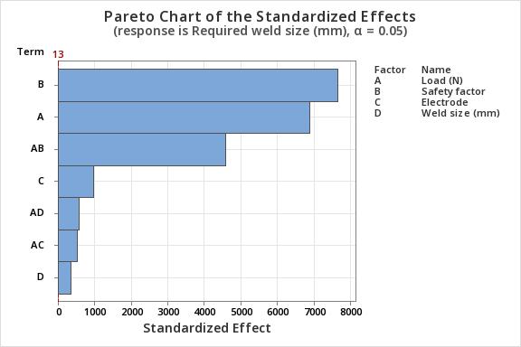
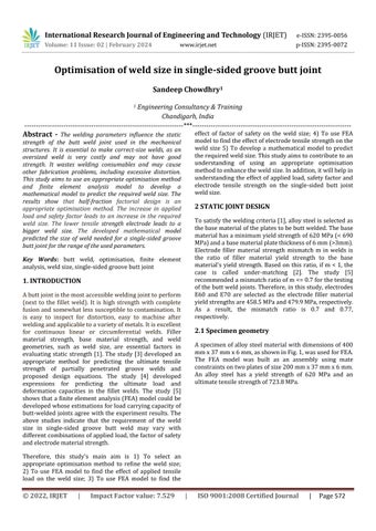
Fig-4: Paretochartshowingthesignificantparameters
The Pareto chart (Fig. 4) and ANOVA table 3 show that safetyfactor,load,electrode,weldsize,interactionsofload and safety factor, load and electrode, and load and weld sizearesignificantatα=0.05.
TABLE-3: ANALYSISOFVARIANCE(ANOVA)OFLOAD,SAFETY
ANDWELD
,
ANOVA table 3 shows that the safety factor has a maximum contribution of 45.45%, followed by load and interaction of load and safety factor contributions of 36.83% and 16.38% towards required weld size, respectively.
The mathematical model of the required weld size equationwithanR-squarevalueof100%is,
Requiredweldsize(mm)=0.57003+0.000047Load(N)0.000833 Safety factor - 0.00025 Electrode + 0.072509 Weld size (mm) + 0.000114 Load (N)*Safety factor0.000026 Load (N)*Electrode - 0.000006 Load (N)*Weld size(mm)(1)

Fig-5:Mainfactorialplotofload,safetyfactor,electrode, weldsizeandtherequiredweldsize
An increase in load leads to an increase in the required weld size. Second, the increase in safety factor also leads to an increase in the required weld size. Third, electrode E60 leads to a higher required weld size than electrode E70. Fourth, the effect of selected weld size is almost negligible. However, the electrode and selected weld size contributions to the required weld size are 0.76% and 0.10%,respectively.
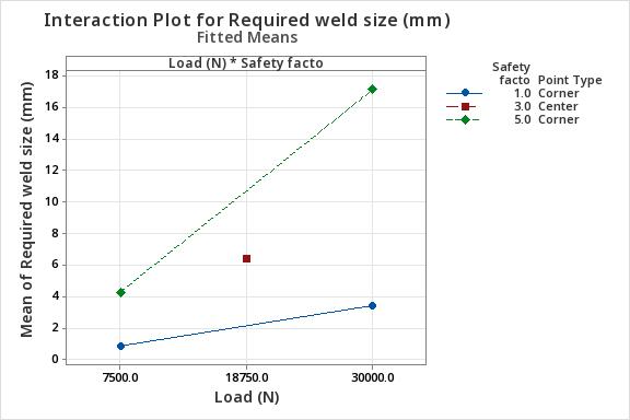
Fig-6:Interactionplotofload,safetyfactorandthe requiredweldsize
The interaction plot in Fig. 6 of the load and safety factor showsthatanincreaseinsafetyfactorandloadleadstoan increaseintherequiredweldsize.
To conduct an optimisation study to minimise the requiredweldsizewithpass,thepassandfailvalueswere stored in separate column as 1 and 0, respectively. If the value obtained of the required weld size from the simulation study is less than the selected weld size, it is recorded as pass in column 7 of Table 2 and vice-versa. Fig. 7 shows an optimised value of the load of 30000N, safety factor of 1, E70 electrode, and weld size of 3 mm, which will give a minimum required weld size of 3.1598 mmwithapass.

Fig-7:Optimisationresultsofload,safetyfactor,electrode, weldsizeandtherequiredweldsize
Fig-8:Screenshotofdisplayedrequiredweldsizeofthe specimen
The optimised load, safety factor, electrode and weld size valueswereappliedtotheFEAmodel.Theobtainedvalue oftherequiredweldsizeis3.1642mm,asshowninFig8.
6. DISCUSSION
First, the main interaction plot (Fig. 5) shows that the center point does lie on the line joining the start and end points, indicating a linear relationship between the input and response variables. On the other hand, an interaction plotofloadandsafetyfactorinFig.6showsthatthecenter point does not lie on the lines indicating the presence of curvature. However, the ANOVA Table 3 shows that the effectofthecurvaturewithap-valueof0.5isinsignificant at α=0.05. Therefore, it is concluded that the relationship between the input variables and the response variable is linear. Hence, the study accepted H0. It is concluded that half-fraction factorial design is an appropriate optimisationmethod.
Second, the factorial plot in Fig. 5 shows that an increase in the load leads to an increase in the required weld size. In addition, the ANOVA Table 3 shows that an increase in load makes the second highest significant contribution of 36.83%toanincreaseintherequiredweldsizeatα=0.05.
Volume: 11 Issue: 02 | February 2024 www.irjet.net p-ISSN:2395-0072
Therefore, it is concluded that an increase in applied load leadstoanincreaseintherequiredweldsize.
Third,thefactorialplotinFig.5showsthatanincreasein thesafety factorleadstoan increaseintherequired weld size.Inaddition,theANOVAtable3showsthatanincrease in the safety factor makes a maximum significant contributionof45.45%toanincreaseintherequiredweld size at α=0.05. Similarly, the interaction of the load and safety factor makes the third highest significant contributionof16.38%toanincreaseintherequiredweld sizeatα=0.05,asshowninANOVATable3.Inaddition,the interaction plot of the load and safety factor in Fig. 6 shows a more significant slope of the safety factor line thantheloadlineslope.Asaresult,thesafetyfactoreffect ontherequiredweldsizeisgreaterthantheappliedload. Therefore, it is concluded that an increase in the safety factorleadstoanincreaseintherequiredweldsize.
Fourth,thefactorialplotinFig.5showsthatusingtheE60 electrodeleadstoabiggerrequiredweldsizecomparedto using the E70 electrode. In addition, the ANOVA Table 3 shows that an electrode type significantly contributes 0.76% to an increase in the required weld size at α=0.05. Therefore, it is concluded that a lower tensile strength electrodeleadstoabiggerrequiredweldsize.Thisfinding agreeswith[5] thatfiller material strengthisan essential parameterinweldedjoints.
Fifth,equation1showsthemathematicalmodelR-square value of 100%. The difference in the required weld size values obtained using the mathematical model (3.1598 mm,asshowninFig.7)andthroughthesimulationstudy (3.1642 mm, as shown in Fig. 8) is 0.0044 mm (0.44%). Therefore, it is concluded that the developed mathematical model is capable of predicting the required weldsizeforasingle-sidedgroovebuttjointfortherange oftheusedparameters.
7. CONCLUSION
Thestudyhasconcludedthattherelationshipbetweenthe inputvariablesandtheresponsevariableislinear,andthe half-fraction factorial design is an appropriate optimisation method to refine the weld size. Second, an increase in applied load leads to an increase in the required weld size. Third, an increase in the safety factor leads to an increase in the required weld size. Fourth, a lowertensilestrengthelectrodeleadstoabiggerrequired weld size. Fifth, the developed mathematical model is capable of predicting the required weld size for a singlesidedgroovebuttjointintheusedparametersrange.
The limitation of this study is that the data from virtual simulations has been collected for the study. In addition, the single-sided groove dimensions of the butt joint were not designed, neither it has been possible to control the amountofweldpenetrationintheFEAmodel.Thedefault
weld available in the software is used. Further research may be carried out to compare whether there is any difference in the required weld size as per the American WeldingCodeandtheEuroWeldingCode.
REFERENCES
[1] AWS Committee on Structural Welding, 2000, “AWS D1.1-Structural Welding Code–Steel,” American Welding Society,Miami,FL.
[2] CEN, 2004, “Eurocode 3: Design of Steel Structures Part 1–8: Design of Joints,” European Committee for Standardization,Brussels.
[3] Gagnon, D. P., and Laurie Kennedy, D. J., 1989, “Behaviour and Ultimate Tensile Strength of Partial Joint Penetration Groove Welds,” Can. J. Civil Eng., 16(3), pp. 384–399
[4] Lesik, D. F., and Laurie Kennedy, D. J., 1990, “Ultimate Strength of Fillet Welded Connections Loaded in Plane,” Can.J.CivilEng.,17(1),pp.55–67.
[5]Khurshid,M.,Barsoum,Z.,andBarsoum,I.,2015,“Load CarryingCapacitiesofButt-WeldedJointsinHighStrength Steels,” ASME. Journal of Engineering Materials and Technology,”137,pp.1-9.