
International Research Journal of Engineering and Technology (IRJET) e-ISSN: 2395-0056
Volume: 11 Issue: 02 | Feb 2024 www.irjet.net p-ISSN: 2395-0072
International Research Journal of Engineering and Technology (IRJET) e-ISSN: 2395-0056
Volume: 11 Issue: 02 | Feb 2024 www.irjet.net p-ISSN: 2395-0072
Mallikarjuna G D1, Dr. Sheshadri G.S2 ,
1Assitant Professor, Department of Electrical & Electronics Engineering, Tontadarya College of Engineering, Gadag, Karnataka, India.
Abstract
Power electronic converters were developed to integrate solar panels to the electric grid. Inverters are required to convert the direct current power of the PV array into the alternating current required for loads. Multilevel inverters are now frequently used in solar systems. Multilevel inverters have various advantages over conventional inverters to use in high power applications. The performance of the Active Neutral Clamped Inverter (ANPC) multilevel inverter (MLI) is evaluated in order to improve power quality. The simulation results presented show that the comparison with the Diode Clamped Multilevel Inverter (DCMLI), Capacitor Clamped Multilevel Inverter (CCMLI) and the proposed ANPC Multilevel inverter which generates less harmonics, less losses and better efficiency in the micro grid system. A simulation is performed on the MATLAB 2018bversionsystem.
Key Words: CCMLI, DCMLI, Losses, Multi level inverter, SPWM,Powerlosses,THD
The usage of renewable energy resources (RES) has increased rapidlycompared tononrenewablesources [12]. When compared to other options utilized in power applications, photovoltaic generation is becoming a more significant renewableresource [3] becauseitproduces no noise,pollution,fuelcosts,ormaintenancerequirements.
Inheavydutyindustriesandhighvoltageapplications,the use of multilevel inverters are becoming common since many of the machinery uses electrical drives. The advantagesofmultilevelconvertersistheirsmalleroutput voltage step, which results in high voltage capability, lower harmonic components, lower switching losses, better electromagnetic compatibility, and high power quality [4]. Also it can operate at both fundamental switching frequency and high switching frequency Pulse Width Modulation. It must be noted that lower switching frequency usually means lower switching loss and higher efficiency [5]. Today, multilevel inverters are extensively used in medium voltage levels with high-power applications. The field of applications includes use in
2Professor, Department of Electrical & Electronics Engineering, Sri Siddhartha Institute of Technology, SSAHE, Tumukuru, Karnataka, India.
laminators,pumps,conveyors,compressors,fans,blowers, and mills Uninterruptable Power Supply (UPS), DC power source utilization, induction heating, high voltage direct currentpowertransmission,variablefrequencydrive,etc. One clear disadvantage of multilevel power conversion is the great number of power semiconductor switches needed. Another disadvantage of multilevel power converters is that the small voltage steps are typically produced by isolated voltage sources or a bank of series capacitors. Isolated voltage sources may not always be readily available and series capacitors require voltage balance. Multilevel inverters are more popular than conventional two-level inverters [6-7].Thisisduetotwolevel limitation when handling high voltage and power. Transformerless multi-level inverter topologies replace power losses and act as voltage source inverters. The output of the multilayer inverter simulation will be compared in order to see an improvement in power quality, with a focus on losses, efficiency and total harmonicdistortion(THD).
2. Overview of Multilevel Voltage source Inverter Topologies
2.1 Multilevel Voltage-Source Inverters
Multilevel voltage-source inverters (VSIs) are power electronic converters used in many different applications, including as motor drives, renewable energy systems, and high-voltage direct current (HVDC) transmission. These inverters create stepped or layered waveforms by synthesizinganoutputvoltagewaveformfromavarietyof DC voltage sources. Multilevel inverters [8-9] have an advantage over traditional two-level inverters in that they can produce an output voltage that is almost sinusoidal, with less harmonic content and less voltage stress on the switching components. As a result, they work particularly effectivelyinsituationsthatcallforhighvoltagelevelsand excellent voltage waveforms. The different multilevel invertersare
Diode-Clamped Multilevel Inverter (Neutral-Point Clamped Inverter): Firstly in his kind of multilayer inverter connectsmany DCvoltage sources inseriesusing clamping diodes and diodes. The number of voltage sources employed and the clamping diode [10] design controlthevoltagelevelsattheoutput.Inverterswithtwo, three, and five levels are common configurations. They
International Research Journal of Engineering and Technology (IRJET) e-ISSN: 2395-0056
Volume: 11 Issue: 02 | Feb 2024 www.irjet.net p-ISSN: 2395-0072
havelimitedscalabilitywhilebeingreasonablyeasytouse andreasonablypriced.Diodeclampedinverterdrawbackis having higher switching losses and less efficiency. Due to the disadvantages furthermore in the next type, CCMLI is explained.
Flying Capacitor Multilevel Inverter: Inthissecondtype of MLI in order to establish intermediate voltage levels between the DC voltage sources, flying capacitor inverters employ capacitors. By dynamically modifying the capacitors'charginganddischarging,thevoltagelevelsare managed [11]. Multilevel Flying capacitor (FC) inverters are appropriate for medium-voltage applications because they can achieve a wide range of voltage levels. FC is not utilizedinrenewableenergysources becausetheyrequire additional capacitors, which makes balancing procedures moredifficult.MoreoverFCMLIisnotusedinRES,sointhe nexttypehybridMLIisexplained.
Hybrid Multilevel Inverter: In the third type of MLI the profit from the unique features of each of the aforementioned topologies, hybrid multilevel inverters integrate two or more of them. For instance, to achieve a balance between complexity, cost, and performance, a hybridinvertermightincludeacascadedH-bridgeinverter and a diode-clamped inverter [12-13]. The utilization of separateDCsourcesforeveryHybridbridgeistheprimary drawback Hence the following system is proposed as a researchobjective.
In the proposed system simulation work done on one dc source of 90kw solar photovoltaic system is connected to grid through unified power quality conditioner (UPQC) The unbalanced load and non linear load (100 ohms) is connectedtoproposedsystem.Furtherdiodesinthediode clamped multi level inverter is been replaced by active semiconductor devices. In the proposed Active Neutral Clamped MLI, less number of semiconductor switches is used to get the desired output voltage and to show good efficiency. The phase shifted Sinusoidal pulse width modulationtechniqueisutilizedtogeneratethegatepulse. Thetechniqueiscontinuedinnextdiscussion.
2.2. Sinusoidal PWM technique
The main objective of the SPWM [14] is to control the inverter output voltage and frequency. SPWM consist of two signals, first one is sinusoidal signal and second is triangular signal. Sinusoidal signal is also called as reference signal and triangular signal is called as carrier signal. Reference signal compared with carrier signal to produce pulses. These generated pulses are given to switches of multilevel inverters to produce desired output voltage through the LC filters. Phase-Shifted Pulse Width Modulation (PS-PWM), often referred to as Phase-Shifted SinusoidalPulseWidth.HenceSPWMisappliedtoinverter togeneratethepulses.Likewiseparametersofthedifferent multilevelinverterareexplainedinnextsection.
3. Measurable Parameters of different types of MLI
3.1. Total Harmonic Distortion (THD)
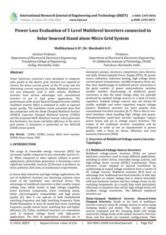
THD is a measurement of the harmonic distortion is characterized as the ratio of the sum of the powers of all
harmonic components to the power of fundamental frequency. Total Harmonic Distortion can be determined bytheexpression(1)is (1)
In the expression (1) I1 is the fundamental component of signal and I2 to I∞ is the harmonics of same signal. THDis usedtocharacterizethelinearityofsystemsandthepower qualityofelectricpowersystems.
According to IEEE standard of THD limits, total harmonic currentdistortionshallbelessthan5%ofthefundamental frequencycurrentatratedinverteroutput
The total power losses ofswitching devices consist of two partssuchasconductionlossesandswitchinglosses Plosses=Pconduction+Pswitching (2)
Where Pconduction is calculated as multiplication of collector emitter voltage drop (VCE(ON)) and collector current (IC(on)) duringON stateandPswitching isONandOFFstateofpower switch. Usually in many literature Plosses are calculated based on simulation results and they don’t consider theoretical results [15]. More the switching frequency increases losses, the proposed system working in fundamental frequency percentage of losses occur in inverterisless
3.3. Efficiency
Efficiency is a measurable concept that may be calculated by the output to input ratio. The system's input power comesfromthepowerdeliveredbythePVarrays,whileits outputpowercomesfromthegrid.
4. Switching States and Modes of operation of multilevel inverters
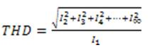
4.1. Diode Clamped Multi-Level Inverter
Diode clamped MLI is shown in Fig. 1. Number of DC bus capacitor in a multi level inverter is decided by (n-1), Number of switches in Multilevel inverter is decided by 2*(n-1),VoltagesourceisdecidedbyVdc/(n-1)&clamping diode is given by(n-1)*(n-2). Where ‘n’ is number oflevel ofaninverter.
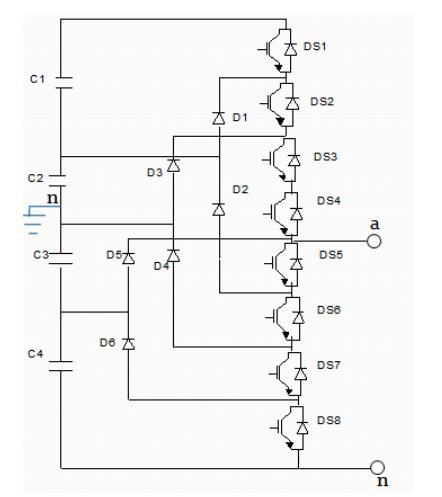
Fig.1:DCMLI-5Lconverter
International Research Journal of Engineering and Technology (IRJET)
Volume: 11 Issue: 02 | Feb 2024 www.irjet.net
TheDCbusvoltageissplitupintothreelevelsasshownin Fig.1.Five-level diode-clampedconverterinwhichtheDC busconsistoffourcapacitorC1,C2,C3,C4forDCbusvoltage Vdc, the voltage across each capacitor is Vdc/4 and each device voltage stress will be limited to one capacitor voltagelevelsVdc/4throughclampingdiodes.
Switchingstatesofthe5LDCMLIisgivenintable1.
Table1:Switchingstatesofthe5LDCMLI
Switching States
Modesofoperation
a. For voltage levels Van= Vdc/2 all upper switches S1-S4areturnedON.
b. ForvoltagelevelVan=Vdc/4,turnonthreeupper switchesS2-S4andlowerswitchS5.
c. For voltage level Van=0, turn on two upper switchesS3andS4andtwolowerswitchesS5and S6.
d. ForvoltagelevelsVan=-Vdc/4,turnononeupper switchS4andthreelowerswitchesS5-S7.
e. For voltage levels Van= -Vdc/2, turn on all lower switchesS5-S8.
3.2. Capacitor Clamped Multilevel Inverter
The DC bus voltage is split up in to three levels as shown inFive-levelcapacitor-clampedconverterinwhichthe DC bus consist of four capacitors C1,C2,C3,C4 for DC bus voltage, the voltage across each capacitor is Vdc/4 and eachdevicevoltagestress will belimited to onecapacitor voltage levels Vdc/4 through clamping capacitor. CapacitorclampedMLIisshowninFig.2.
Mainswitches=2(n-1)=8, DCbuscapacitor=(n-1)=4
Balancingcapacitor=(n-1)(n-2)/2=6.
Switchingstatesofthe5LCCMLIisgivenintable2.
Table2:Switchingstatesofthe5LCCMLI Switching
Modesofoperation
a. For voltage levels Van= Vdc/2 turn on all upper switchesS1-S4.
b. ForvoltagelevelVan=Vdc/4,turnonthreeupper switchesS1-S3andlowerswitchS5.
c. For voltage level Van=0, turn on two upper switchesS1andS2andtwolowerswitchesS5and S6.
d. ForvoltagelevelsVan=-Vdc/4,turnononeupper switchS1andthreelowerswitchesS5-S7.
e. For voltage levels Van= -Vdc/2, turn on all lower switchesS5-S8.
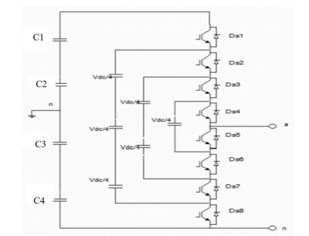
Fig. 3 shows that ANPC-5L converter. In Fig. 3 each leg consist of 6 semiconductor switches, one dc source with two separate capacitors and totally for 5-level ANPC inverterof3legneed18switchestooperate.
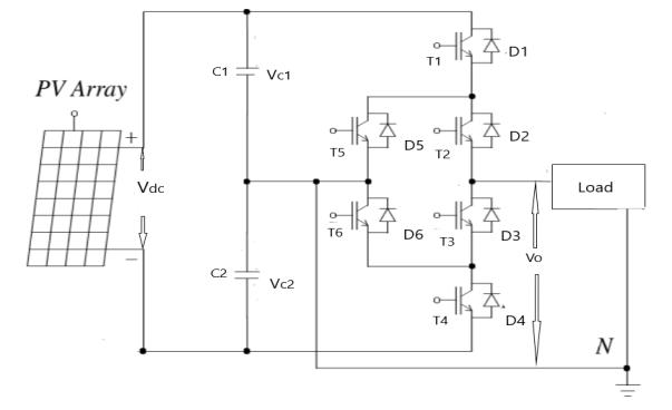
Fig.3:ANPC-5Lconverter
PV array connected to load through proposed inverter. ThegatepulsegiventopowerswitchesareT1,T2,T3,T4 is responsible for levels and inverse pulse of T1, T4 given to T5, T6 respectively to avoid the DC-link short circuit, actively control switching angles and reduce harmonics.
International Research Journal of Engineering and Technology (IRJET) e-ISSN: 2395-0056
Volume: 11 Issue: 02 | Feb 2024 www.irjet.net p-ISSN: 2395-0072
Vc1andVc2representthetwosplitcapacitorvoltageshas samebalancedvoltage.Vdcrepresenttheinputvoltage.Vo is the output voltage. Switching states of the 5L MLI is givenintable.3.
Table3:Switchingstatesofthe5LMLI
Mode
1
2
3
4
5
4. Simulation, Results and Discussions
Modesofoperation
a. Mode 1 (+2): In this, the switches T1 and T2 are turnedONandtheloadvoltageisVdc.Thecurrent flowsthroughVdc-T1-T2-load.
b. Mode 2 (+1): In this, the switches T5 and T2 are turnedONandtheloadvoltageis+(Vdc-Vc1).The currentflowsthroughC1-T5-T2-load.
c. Mode3(0):InthisalltheswitchesareOFFandthe voltagearoundloadiszeroshowninFig.3(c).
d. Mode 4 (-1): In this, the switches T3 and T6 are turnedONandtheloadvoltageis–(Vdc-Vc2).The currentflowsthroughload-T3-T6-C2.
e. Mode 5 (-2): In this, the switches T3 and T4 are turned ON and the load voltage is –Vdc. The currentflowsthroughload-T3-T4-(-Vdc).
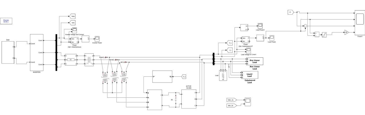
Fig.4.GridconnectedstandalonesolarPVsystem
GridconnectedsolarpvsystemisshowninFig.4.InFig.4solarsystemconnectedtostandalonegridthroughmultilevel inverterandUPQC.Movingforwardtothatthedifferenttypesofmultilevelinverterssimulinkmodelsisdiscussedfurther
5.
International Research Journal of Engineering and Technology (IRJET) e-ISSN: 2395-0056
Volume: 11 Issue: 02 | Feb 2024 www.irjet.net p-ISSN: 2395-0072
Simulink model of Diode clamped 5 level MLI connected to Grid is shown in Fig. 5. The DCMLI is simulated in MATLAB/Simulink2018bversionsoftwarewhereDCMLIofFig.5includeselementsgivenintable4.
6.
Simulink model of Capacitor clamped 5 level MLI connected to Grid is shown in Fig. 6. The CCMLI is simulated in MATLAB/Simulink 2018b version software where CCMLI of Fig. 6 includes elements given in table 4.
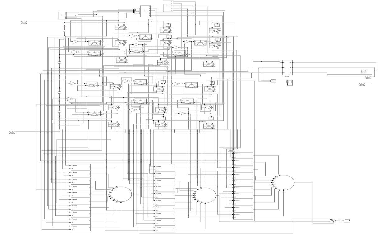
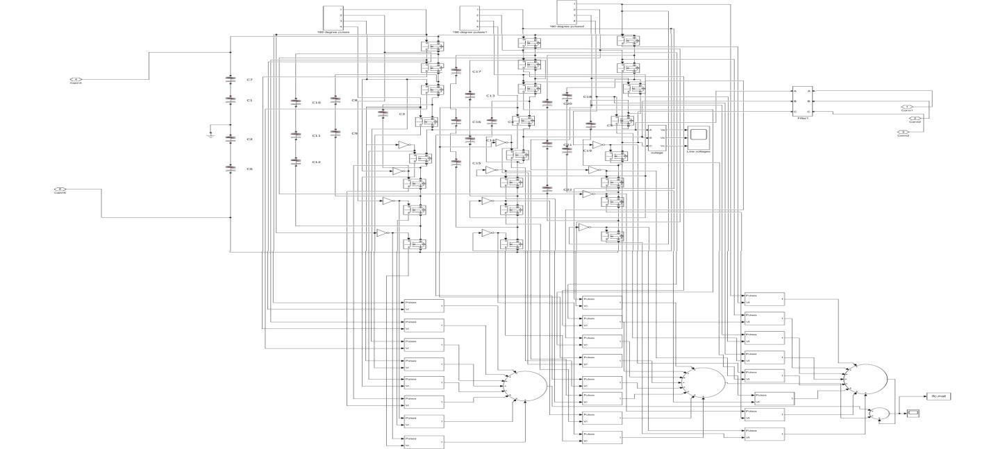
Simulink model of seven level ANPC MLI connected to Grid is shown in Fig. 7. The ANPC MLI is simulated in MATLAB/Simulink2018bversionsoftwarewhereANPCMLIofFig.5includeselementsgivenintable4.
International Research Journal of Engineering and Technology (IRJET) e-ISSN: 2395-0056
Volume: 11 Issue: 02 | Feb 2024 www.irjet.net p-ISSN: 2395-0072
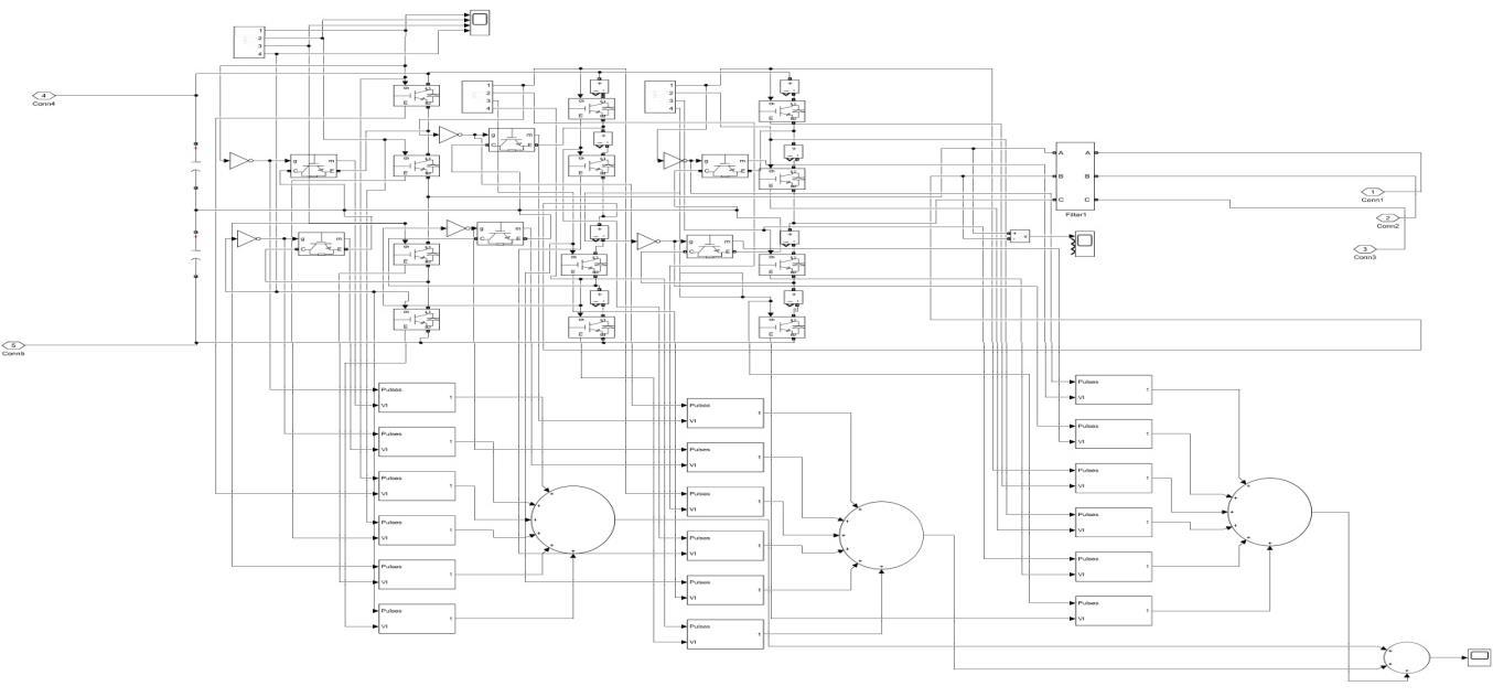
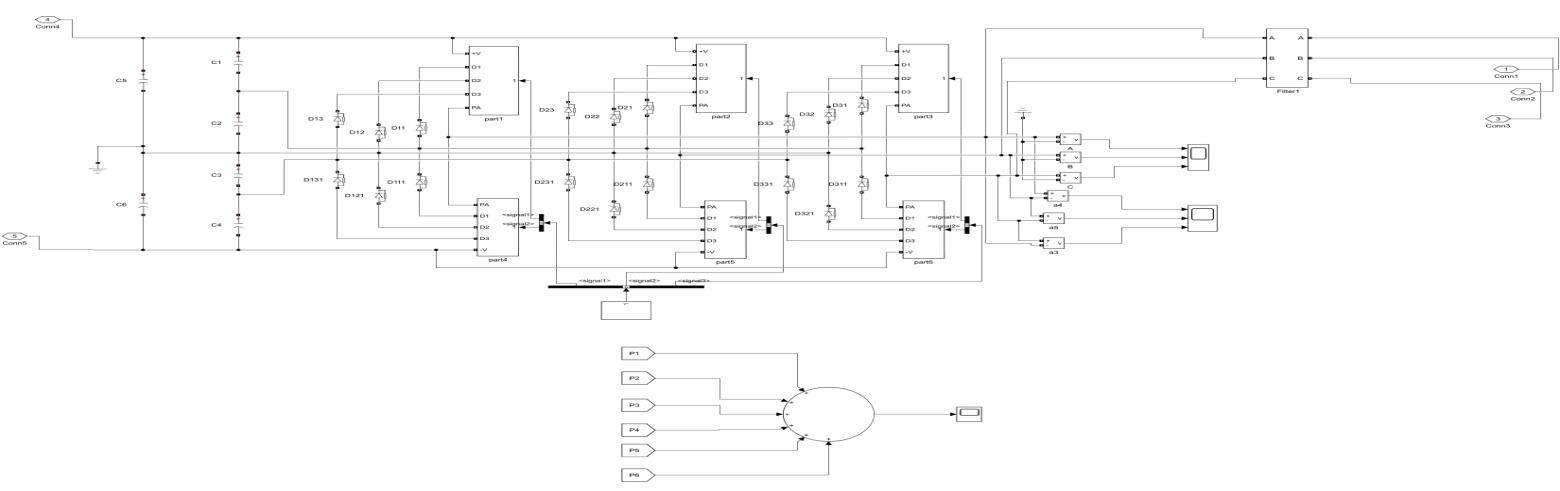
8.ProposedSimulinkModelof5levelANPCMLI
Proposed Simulink model of five level ANPC MLI connected to Grid is shown in Fig. 8. The ANPC MLI is simulated in MATLAB/Simulink2018bversionsoftwarewhereANPCMLIofFig.8includeselementsgivenintable4.Table.4showsthe Parameterscomparisonofdifferenttypesofmultilevelinverters
Table.4.Parameterscomparisonofdifferenttypesofmultilevelinverters InverterType Noof diodes Noofdc link capacitors Noofflying capacitors Noof levels Noof switches
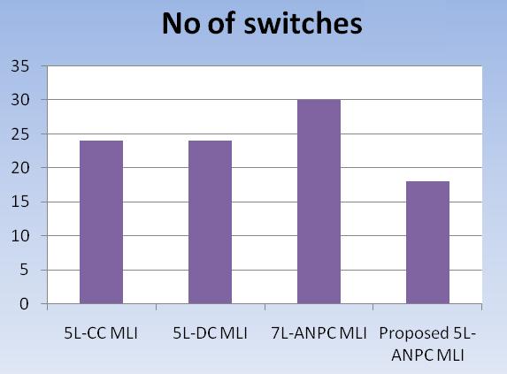
Thecomparisonofswitchesfordifferenttypesofinverter is shown in Fig. 9. In Fig. 9, y-axis shows number of switchesandx-axisshowsthedifferenttypesofMLI.In
Proposed5levelANPCMLI, lessnumberofswitchesused toreducelosses.
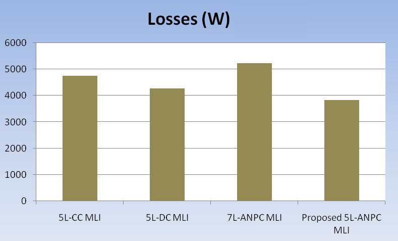
Fig.10.Comparisonoflossesforinverter Further in the comparison of losses for different types of inverterisshowninFig.10.InFig.10,y-axisshowslosses
International Research Journal of Engineering and Technology (IRJET) e-ISSN: 2395-0056
Volume: 11 Issue: 02 | Feb 2024 www.irjet.net p-ISSN: 2395-0072
in watts and x-axis shows the different types of MLI. Fig. 10 shows that VSI suffers more losses (5030 W) due to PWM switching frequency (1KHz) and ANPC have lower loss(3827W)inspiteofmorenumberofswitchesthanVSI as it operates under modulation frequency (50Hz) but the losses are increased to 5240 W as the number of levels increases to 7. The proposed system will increase the efficiency of system due to reduced losses. In the next sectionefficiencyparameterisdiscussed.
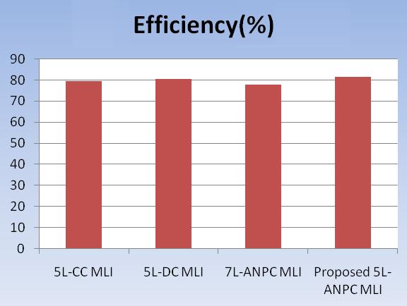
Fig.11 ComparisonofEfficiencyfordifferentMLI
Likewise comparison of efficiency for different MLI is shown in Fig. 11. The ANPC with 7 level shown in Fig. 11 offers low efficiency (77.5%) while ANPC with 5 level offers more efficiency (81.4%) where diode clamped inverter (80.4%) is next to ANPC which is followed by flyingcapacitorMLI(79.25%)andVSI(78%).
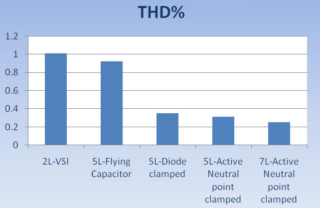
Fig.12.ComparisonofTHD%fordifferenttypesofMLI
Comparison of THD% for different types of MLI is shown in Fig. 12. In Fig. 12, THD% is less in 7 level inverter compared to proposed ANPC five level Multilevel inverter but more switches increases losses and reduces efficiency in7levelMLIasshowninFig.10andFig.11.
5. Conclusion
Thispaperpresentednewactiveneutralclampedfivelevel multilevel inverter topology for the MLI is the best topology. The main concept of this inverter is to use less power electronic switches instead of diodes which reduce losses and improve efficiency The effectiveness of five levelactiveneutral pointclampedinverterbasedSPWMis validated through the simulations in terms of losses, efficiencyandTHD.
[1] Mallikarjuna G D, G.S.Sheshadri, Comparison of Solar Energy System Tools: A Case Study, International Research Journal of Engineering and Technology (IRJET)-(ISSN2395-0056),Vol.6,Issue12,Dec2019.
[2] European Commision, A Vision of Photovoltaic Technology, Directorate-General for Research SustainableEnergySystems,EUR21242.
[3] Mallikarjuna G D, G.S.Sheshadri, Validation of PerformanceevaluationusingMatlab/SimulinkModel of a PV Array, International Journal of Advance ScienceandEngineering(IJASE)–(E-ISSN23495359; P-ISSN 2454 9967), Vol. 6, no. 3, Feb. 2020. doi.org/10.29294/IJASE.6.3.2020.1424-1429.
[4] J. Rodriguez, J. S. Lai and F. Z. Peng, Multilevel Inverters: Survey of Topologies, Controls, and Applications, IEEE Transactions on Industry Applications,Vol.49,no.4,Aug.2002,pp.724-738.
[5] L. M. Tolbert, F. Z. Peng, T. G. Habetler, Multilevel PWM Methods at Low Modulation Indices, IEEE TransactionsonPowerElectronics,Vol.15,no.4,July 2000,pp.719-725.
[6] Mallikarjuna G D, G.S.Sheshadri, Power Quality ImprovementUsingunifiedpowerqualityconditioner in PV sourced stand alone micro grid system, International Journal of Creative Research Thoughts (IJCRT), Vol. 11, Issue 3, ISSN: 2320-2882, 2023. UGC Approved.
[7] A.Ravi,VijayAnand,Modelingandsimulationofthree phase multilevel inverter for grid connected photovoltaic systems, Elsevier, Vol. 85, Issue 11,Nov 2011,Pages2811-2818.
[8] Promod Kumar Verma, Topological Analysis of Multilevel Inverter for Photovoltaic System, International Journal of Engineering Research & Technology (IJERT) ISSN: 2278-0181, Vol. 6, Issue 6, June2017.
[9] Mallikarjuna G D, G.S.Sheshadri, Power Quality Analysis Using Active NPC Multilevel inverter in PV
International Research Journal of Engineering and Technology (IRJET) e-ISSN: 2395-0056
Volume: 11 Issue: 02 | Feb 2024 www.irjet.net p-ISSN: 2395-0072
sourced stand alone micro grid system, paper published in International Research Journal of Engineering and Technology (IRJET), Vol. 10, Issue. 10,Oct.2023,ISSN:2395-0056.
[10] K,Surya Suresh, M.Vishnu Prasad, Analysis and Simulation of New Seven level Inverter Topology, in International Journal of Scientific and Research Publication, Vol. 2, Issue 4, April 2012 ISSN 22503153.
[11] X.YuanandI.Barbi,ANewDiodeClampingMultilevel Inverter,IEEETrans.PowerElectron,Vol.15,no.4,pp. 711-718,Jul.2000.
[12] Sayli Khadse, Rohini Mendole, A 5-Level Single Phase Flying Capacitor Multilevel Inverter, International Research Journal of Engineering and Technology (IRJET)-(ISSN2395-0056),Vol.4,Issue2,Feb.2017.
[13] Mohammadreza Derakhshanfar, Analysis of different topologiesofmultilevelInverters.
[14] Pankaj H Zope, Pravin G.Bhangale, Design and Implementation of carrier based Sinusoidal PWM Inverter, International Journal of Advanced Research in Electrical, Electronics and Instrumentation Engineering,Vol.1,Issue4,Oct 2012.
[15] Abolfazl Babaie, Bagher Karami, Adib Abrishamifar, Improved Equations of Switching Loss and Conduction Loss in SPWM Multilevel Inverters, 7th Power Electronics, Drive Systems & Technologies Conference(PEDSTC2016),IranUniversityofScience andTechnology,Tehran,Iran,16-18Feb.2016,IEEE.
BIOGRAPHIES


Mallikarjuna G D is working as Assistant Professor, Dept of Electrical & Electronics Engineering, Tontadarya College ofEngineering,Gadag,Karnataka, India.


Dr. G.S.Sheshadri is working as a Professor, Dept of Electrical & Electronics Engineering, Sri Siddhartha Institute of Technology, SSAHE, Tumukuru, Karnataka,India.