
International Research Journal of Engineering and Technology (IRJET) e-ISSN: 2395-0056 p-ISSN: 2395-0072
Volume: 11 Issue: 02 | Feb 2024 www.irjet.net
International Research Journal of Engineering and Technology (IRJET) e-ISSN: 2395-0056 p-ISSN: 2395-0072
Volume: 11 Issue: 02 | Feb 2024 www.irjet.net
Sahil Garud1, Manali Choudhari2, Aditya Chakkarwar3 , Dhiraj Badshe4, Nishigandha Darekar5
Vrushali Bhalerao6
1,2,3,4,5DepartmentofMechanicalEngineering,PCCOEPune,India
6 AssistantProfessor,DepartmentofMechanical Engineering,PCCOEPune,India
Abstract - Cricket is the most dominant sport played, especially in India. Training centers for cricket are filled with numerous cricket ball-throwing machines, which are quite expensive, and few functions are manually handled. Here is an attempt to build a cricket ball-throwing machine that is completely automated and cost-effective. The main purpose of the study is to design and develop a ballthrowing machine along with modeling the machine. The machine will be able to adjust to different pitch conditions and will be able to deliver different forms of bowling along with the height adjustment mechanism. To deliver cricket balls ranging from 40 kmph to 130 kmph, two motor mechanisms are used upon which grooved wheels are mounted.
Key Words: Cricket, Cost-effective, Ball throwing machine, bowling varitions, motor mechanisms.
Cricket a popular sport which is played by many countries worldwide [1], enjoys unparalleled popularity, particularly in cricket-crazy nations like India. As sport evolves, there is an increasing demand for innovative training methods that enable players to enhance their skills and grasp various aspects of the game. In modern training facilities, cricket ball-throwing machines have become indispensable tools for players seeking to improve their batting and bowling abilities through precise and consistent deliveries. However, existing machinesoftencomewithlimitationssuchasmanual operationandhighcosts.Thisstudyseekstoaddress these challenges by developing a cricket ballthrowing machine that surpasses conventional solutions available in the market. The primary objective is to create a fully automated and costeffectivemachinecapableofdeliveringvarioustypes ofbowlingandadaptingtodiversepitchconditions. Additionally, the machine will feature a height adjustment mechanism to accommodate players of different statures and skill levels, making it a
versatile and indispensable training companion. At the core of this innovative design lies the integration of two motor systems with strategically positioned groovedwheels.Thiscombinationallowsthemachine to deliver cricket balls at various speeds, from a comfortable 40 mph to a challenging 130 kmph. The precision and consistency provided by these motorized mechanics will assist players in honing their reflexes, refining their shot selection, and improvingtheiroverallbattingproficiency.
Moreover, the incorporation of a ball positioning system enables players to practice various delivery styles,simulatingtheactionsoffastbowlers,spinners, and swing bowlers. This feature not only enhances a batsman's ability to read the ball but also provides bowlers with valuable opportunities to master differentvariationsanddeceivebatsmeneffectively.
2. DESIGN CALCULATIONS AND ANALYSIS
The Design calculation of the ball throwing mechanism is done considering the mass of the ball, kineticenergyaswellastherotationalenergyofthe balltobethrown.
2.1
Design calculation for cricket ball throwing machine involves motor specifications, wheel diameter and grooving,ballspeedrange,etc
A. Motor Power Calculated Values: Motor calculation for cricket ball throwing machines is essential in designing as it determines the motor's capacitytoachievethedesiredballspeedsanddeliver consistent and accurate deliveries. The values are as following:
a.Massoftheball(M):150gm.
b.Maximumvelocityoftheball:151.2kmph(42m/s)
c.KineticEnergyoftheball(KE)=132.3Nm
d.KineticEnergysuppliedbyonewheel=66.15J
International Research Journal of Engineering and Technology (IRJET) e-ISSN: 2395-0056 p-ISSN: 2395-0072
Volume: 11 Issue: 02 | Feb 2024 www.irjet.net
B. Wheel Calculated Values: In wheel calculation
wheel size, rotational speed and grooving are considered to achieve the desired ball speed and typesofdeliveriesforcricketballthrowingmachine. The Rotational Energy of the wheel is given by, R.E.=(1/2)I(ω12–ω22)
M=0.3144kg
Iwheel=0.004472kg-m2
Initially,weknowthatω1=251.3rad/secandR.E= 66.15J
So, substituting in the above equation we can calculate ω2 = 250 rad/sec So, we can see that the angular velocity gets reduced by a factor of 1.0179. In a similar manner, we reduce the rpm of the wheels by some amount in each turn and calculate thevelocityoftheballforeachcase
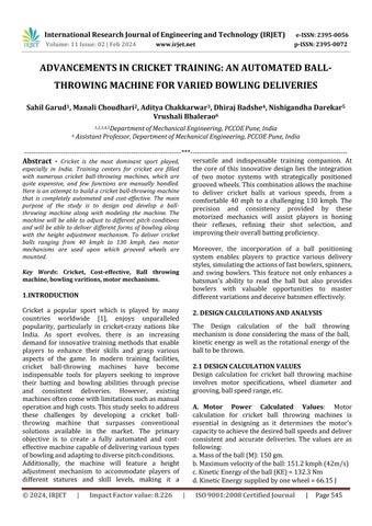
C. Obtain off spin and leg spin at different output speeds: Thespeedoftheabovetwomotors will be adjusted accordingly to obtain the required spin. If the rpm of the left-hand side motor is more than the off-spin is produced for a right-handed batsmanandif the right-hand side’smotor speedis morethantheleg-spinwillbethere.
The following, Figure 1, shows the ball variations that are considered for the design and analysis of the cricket ball throwing machine. Ball machines have the same benefits for cricket players irrespective of their performance level. Amateurs and professionals alike enjoy the same perks in a practice session. Many professionals relish the successofenhancingtheirgamebypracticingwitha bowling machine.
Calculationof the stand for the cricket ball-throwing machine is essential for stability, adjustability, and user-friendliness.
Heightofthestand=4ft1inch=1244.6mm,
Typeofrod=hollowsquarecrosssectionrod
Massofthemechanism=5kg,
Lengthofthestand=Breadthofthestand=250mm,
Thicknessofrod=5mm
Force on a single leg of stand = 1/3*m*g=1/3*5*9.8 =16.35N
AreaofOutersection(A1)=(B*T)=62500mm^2
Areaofinnersection(A2)=[B’*T’]=60516mm^2
TotalAreaunderload=A1-A2=1984mm^2
Stress=F/A=8.241*10-3MPa
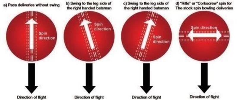
With the help of ANSYS the structural and stress analysis of cricket ball throwing machine is done. It helps to ensure safety, performance optimization, failureprediction,andreliability.
Theoveralldeformationof thecricket ball throwing machinebeginsatthecenterofthebaseplatewhich is zero and steadily grows to the end of the base plate, where it reaches its maximum which is 0.00017693m.
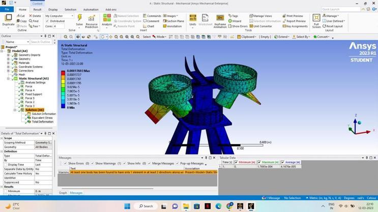
B. NormalShearAnalysis:
Normalstressanalysisaidsinidentifyingareasofthe machine that may experience excessive tensile or compressiveloads.
The normal stress analysis revealed areas of high-
International Research Journal of Engineering and Technology (IRJET) e-ISSN: 2395-0056 p-ISSN: 2395-0072
Volume: 11 Issue: 02 | Feb 2024 www.irjet.net
stress concentration and regions experiencing significant loading. The high-stress regions could potentially be susceptible to failure or fatigue over time. The following figure shows the normal stress analysis of the machine which had been achieved usingANSYSsoftware
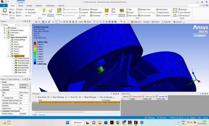
Thestressintensityanalysisdeterminesthelevelof intensityofstressconcentrations.
The ball-throwing mechanism has minimal stress throughout the assembly, however, there is a modest increase in stress at the joint between the wheelandthebaseplate.
The minimum stress throughout the assembly is 0.28983, and the modest increase in stress at the joint is from 1.2655e7 Pa to 3.7964e7 Pa. The following figure shows the stress intensity of the machinewhichisdeterminedusingsoftwareANSYS.
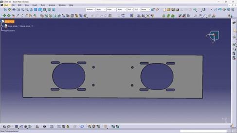
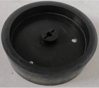
The base plate is made of Mild steel of grade A36. It also features remarkable corrosion resistance in both interiorandexteriorconditions.Thedimensionsofthe plate are 500 x 120 mm, having a thickness of 4mm.The base plate is designed in such a way that it will be easy to deliver cricket balls of different dimensions because of the adjustment provided. Its functionisthatitwillbeusedtomountthemotorand the wheel, and it will be used to adjust the distance between the two wheels. The manufacturing process of laser cutting is used to make holes of different dimensionsonasolidmetalplate.
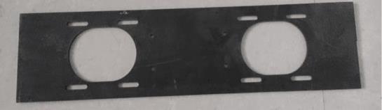
The design of the base plate was initially made using the dimensions and the driftingof the base plate.The CAD model was made using CATIA V5. This was helpfulinthemanufacturingofthebaseplate.Figure5 shows us the CAD Model of the base plate. The Base platewasmanufacturedusingMildsteelofgradeA36 ofthickness4mm.Theplatewasmanufacturedusing a laser cutting machine at Gujar Industries, Pune. Figure 6 shows the actual manufacturing of the base plate
Volume: 11 Issue: 02 | Feb 2024 www.irjet.net
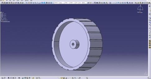
The wheel material used is ASA - Acrylonitrile Styrene Acrylate. The wheels mounted adjacent to each other will slightly compress the cricket ball enteringthemachine for its delivery.The wheels are rotatedbymountingthemontheelectricmotors.The wheel will be directly joined to the motor shaft. The wheel is manufactured using an injection molding manufacturingprocess.
The wheel has an outer diameter of 180mm and an inner diameter of 160mm. The width of the wheel is 60mm. The grooves made in the wheel are 5mm in size.
DesignofWheel:
ThedesignofthewheelwasmadeusingCATIAV5.It was made using proper dimensions which then was usedformanufacturingpurposes.Figure7showsthe CAD Model of the wheel. The wheel was made using ASA - Acrylonitrile Styrene Acrylate which helps in cutting down the weight while keeping the strength and load capacity of the wheel same. Figure 8 shows theactualmanufacturingofthewheel.
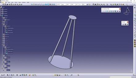
3.3. STAND
ThestandismadeofMildsteelmaterial.Thestandis provided with the facility of height adjustment for cricketball deliveries atdifferentheights.The height of the stand is 1244.83mm. The circular plate at the top is 200mm in diameter. There are in total three legsattachedtothecircularplate.Theanglebetween thelegsofthestandis120°.
DesignoftheStand:
ThedesignofthestandwasmadeusingCATIAV5.It was made using proper dimensions which then was
2395-0072
used for manufacturing purposes. Figure 9 shows the CADModelofthewheel.[5]
The wheel was made using Mild steel material which helps in cutting down the cost while keeping the strength and load capacity of the wheel same. Figure 10showstheactualmanufacturingofthestand.
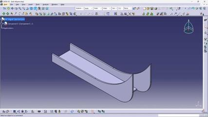
3.4. BALL RAMP
Whentheballdropsfromtheballfeederitisdropped upon the ball position aligner. [4] The aligner maintains the position of the ball attained in the feeder. Bymaintainingthe positionof thecricketball, the ball further passes through the wheels and a certainballdeliveryisachieved.
DesignoftheBallRamp:
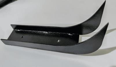
The ball ramp model was made using CATIA V5. The rampisusedtoproperlypositiontheballalongafixed path. [4] Figure 11 shows the CAD model of the Ball ramp.Themanufacturingoftheballrampwasdonein Gujar Industries. The ball ramp was manufactured using a laser cutting machine and then welding the parts together. The actual ball ramp as seenin Figure 12,wasmadeofmildsteelofthickness3mm.
International Research Journal of Engineering and Technology (IRJET) e-ISSN: 2395-0056 p-ISSN: 2395-0072
Volume: 11 Issue: 02 | Feb 2024 www.irjet.net
4.1 SPEED CHANGE vs PITCHING DISTANCE
(keeping angle constant)
Herewekepttheangleconstantoftheballthrowing mechanism and changed the speed of the machine, followingresultswereobserved:
A.Withanincreaseinspeed,thepitchingpointwas inbetweenthe4mto6mslot.
B. With a decrease in speed, the pitching point was inbetweenthe6mto8mslot.
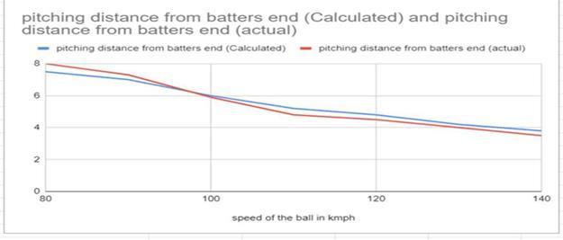
Graph -1:SpeedChangevsPitchingDistance
Graph1showsthatforeveryincreaseof10kmphin “speed of the ball inkmph”,“pitchingdistance from batterendinmeters”decreasesbyabout0.639m.
4.2 ANGLE CHANGE vs PITCHING LENGTH
(keeping speed constant)
Here we kept the speed constant of the ball throwing mechanism and changed the angle of the machine,followingresultswereobserved:
A. With an increase in the angle, the pitching point goesawayfromthemachine.
B. With a decrease in the angle, the pitching point movedclosertothemachine.
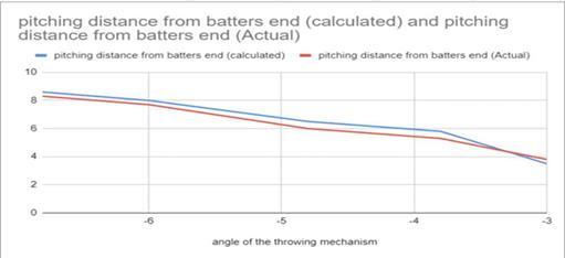
Graph -2:AngleChangevsPitchingLine
Graph 2 shows that for every increase of 1 in the “angle of the throwing mechanism”, “pitching distancefrombatterend”decreasesbyabout1.25
4.3 ANGLE vs PITCHING LINE
Herewekeptthespeedconstantoftheballthrowing mechanism and changed the horizontal angle of the machine,thefollowingresultswereobserved:
A. When the angle takes a negative value (left of middle stump) ball was observed to be pitching in lines outside the off stump (for a right-hander batter).
B. When the angle takes a positive value (right of middle stump) ball was observed to be pitching in lines outside the leg stump (for a right-hander batter).
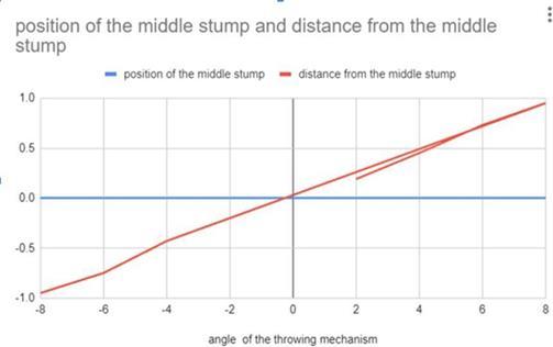
Graph -3:AnglevsPitchingLine
Graph2showsthatforeveryincreaseof10in“angle of the throwing mechanism”, “distance from the middlestump”increasesbyabout1.18m.
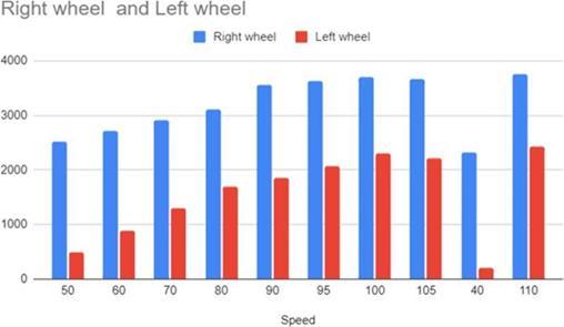
4.4 SPEED vs RPM. Of WHEEL
Here we change the speed ball throwing mechanism andobservethechangeintheRPMofthewheel.
A. With an increase in the speed of the bowling machine, the RPM of the wheels increases (and vice versa).
B.Atthelowestspeedvalue,40,thelowestvaluefor the“Rpmofwheel”wasobserved(1201).
International Research Journal of Engineering and Technology (IRJET) e-ISSN: 2395-0056 p-ISSN: 2395-0072 Volume: 11 Issue: 02 | Feb 2024 www.irjet.net
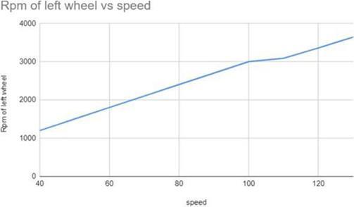
Graph -4:SpeedvsRPMofWheel
Graph 4 shows that for every increase of 10 in “speed”,“Rpmofthewheel”increasesbyabout266.
4.5 RPM. Of LEFT AND RIGHT WHEEL vs SPEED OF BALL (FOR OFF SPIN)
Here,theRpmofthewheelwaschangedtoobserve differentvariationsofspinatdifferentspeedsofthe balldelivery.Thefollowingresultswereobserved:
A. Spin was observed at delivery speeds below 105kmph.
B.WhentheRpmoftheleftwheelwasgreaterthan the right wheel, an off spin was observed. Where 40kmph had the lowest values for “Right wheel rpm”(250)and“LeftwheelRpm”(2303).
C. When the Rpm of the right wheel was greater than the left wheel, leg spin was observed. Where 40kmph had the lowest values for “Right wheel Rpm”(2314)and“LeftwheelRpm”(200).
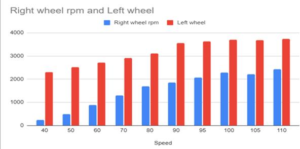
Graph -5:RPMOfRightandLeftwheelvsSpeed(offspin)
Graph 5 shows that for every increase of 10 in “Speed”,“Rightwheelrpm”increasesbyabout321.
Graph 6 shows that for every increase of 10 in “Speed”,“Rightwheelrpm”increasesbyabout222.
After conducting the literature survey, design calculationsandmanufacturingofdifferentparts,the ball throwing machine was developed using various manufacturing techniques such as molding, welding, rubber coating, laser cutting, drilling, grinding, and others. After testing the machine and taking observations,thefollowingconclusionsweredrawn.
1. The machine works in perfect condition for 45 mins regularly. The machine performed accurately with slight variations at high speed and accuracy was observed to increase at lower speed.
2. With the change in the angle of the throwing mechanism different pitching points were obtained. When the angle was increased the pitchingpointwas goingawayfrom themachine andviceversa.
3. The ball is bowled from a speed of 40 kmph to 130kmph.
4. Changesintherotationsperminute(rpm)ofthe wheel result in an increase and decrease in the ballspeed.
5. With changing the speed of the single wheel of theballspinwasobserved.
Through these observations, it was evident that the ball throwing machine performed very well, demonstratingvariationsinspeed,accuracy,pitching points, and spin generation based on adjustments madetotheangleandRPM
International Research Journal of Engineering and Technology (IRJET) e-ISSN: 2395-0056 p-ISSN: 2395-0072
Volume: 11 Issue: 02 | Feb 2024 www.irjet.net
[1] Abhijit Mahapatra, Avik Chatterjee, Shibendu Shekhar Roy, Modeling and Simulation of a Ball Throwing Machine, NaCoMM-2009MMRAIAAM20,December17-18,2009.
[2] Mohammed Asif Kattimani, Ahmed Raza, Syed Ameer, Design and Fabrication of Cricket Ball Launching Machine, Mantech Publications, Journal of Industrial Engineering and Its Applications Vol 4 Issue 3,2019.
[3] Tara Singh Thakur, K Srinivasa Chalapathi, Ibrahim Syed, Integrated Novel Multi-Game Ball Throwing Machine: Design and Fabrication,InternationalJournalofScientific & Engineering Research Volume 10, Issue 5, May-2019ISSN2229-5518,May-2019.
[4] L Justham and A West, Design, and development of a novel, integrated bowling machine for cricket, JSET50 Proc. IMechE Vol. 223 Part P: J. Sports Engineering and Technology, 29 June 2009.
[5] Abhishek Patra Singh, Anuj Kumar Jain, design-data-book-9789353166304-india
Parteek Mahajan, Design and Fabrication of a Ball Projecting Machine, International Journal of Advance Research and Innovation,September2016.
[6] V. B. Bhandari, Machine Design Data Book, 2ndEditio. Mc Graw Hill, 2019. Accessed:Jul. 26, 2023. [Online]. Available: https://www.mheducation.co.in/machine-
[7] V. B. Bhandari, Design of machine elements. Tata McGraw-Hill, 2007. Accessed: Jul. 26, 2023. [Online]. Available: https://books.google.com/books/about/Desi gn_of_Machine_Elements.html?id=f5Eit2FZe_ cC © 2024, IRJET | Impact Factor value: 8.226 | ISO 9001:2008 Certified