
International Research Journal of Engineering and Technology (IRJET) e-ISSN: 2395-0056
Volume: 11 Issue: 02 | Feb 2024 www.irjet.net p-ISSN: 2395-0072
International Research Journal of Engineering and Technology (IRJET) e-ISSN: 2395-0056
Volume: 11 Issue: 02 | Feb 2024 www.irjet.net p-ISSN: 2395-0072
Nishigandha Darekar1 , Dhiraj Badshe2 , Aditya Chakkarwar3 , Manali Choudhari4, Sahil Garud5
Vrushali Bhalerao6
1,2,3,4,5Department of Mechanical Engineering, PCCOE Pune, India 6 Assistant Professor, Department of Mechanical Engineering, PCCOE Pune, India ***
Abstract - Cricket is a highly popular sport that holds significant dominance. Within cricket training centers, there is use of expensive cricket ball throwing machines, some of which require manual operation for certain functions. To create an efficient and affordable solution, it has embarked on the development of a fully automated cricket ball throwing machine. It has incorporated a ball positioning mechanism to facilitate the delivery of different types, along with a stop-go mechanism and a three-way ball feeding system. With the help of Software analysis results and practical testing the ball positioning mechanism is instrumental in achieving diverse ball positions as they enter the ball throwing mechanism.
Key Words: Cricket, Automated, cost effective, Design, Stop-Mechanism, Ball feeding machine.
1.INTRODUCTION
Cricketisapopularsportwhichisplayedbymanycountries worldwide [1]. The sport of cricket requires dedication, integrity, and finesse. Along with years of practice, it also demands passion and devotion. Cricket involves batsmen andbowlersalongwithfielders.Bowlingincricketincludes bowlersbowlingatdifferentlengthssuchasyorkerlength, goodlength,shortlength,andstylessuchasoffspin,legspin, inswingandoutswing[1].Bowlfeederactsasacricketball sourceforthebatsman.Bowlfeedersareusedespeciallyin net practices.A ball feederisportable and used indoor as wellasoutdoortraining.Ascricketisoneofthemostfamous sportsintheworld,alotofpeopleworldwideareinterested in taking lessons. Hench ball feeders help such people in improvingtheirgame.Currentlythereareballfeederswhich deliveronlyonekindofcricketballtothebatsmanandare quite expensive. In addition to that the ball has to be released manually by the trainer in intervals. The ball feederswhicharecurrentlyinthemarketareprimitiveand expensivetoo.Theseballfeedersdeliversingletypeofballs without any ball positioning variation. Here an attempt is madetodesignanddeveloptheballfeederandpositioning machine.Thegoalistodevelopanefficientandaffordable automated cricket ball feeder machine. The machine will deliver different types of balls such as leather balls, hard tennis balls as well as wobble balls. The machine also incorporatesastop-gomechanismandaballfeedingsystem. Thefeedercanstore18cricketballsintotal.Solenoidvalves
areusedtocarryoutthestop-gomechanism[2].TheStopGomechanismwillallowdeliveryofoneballata time[2]. The ball positioning mechanism plays a crucial role in achieving diverse ball positions as they enter the ball throwingmachine[3],[4].Theballpositioninghelpsinthe achievingofdifferenttypesofcricketballdeliveries.Theball positioningcanbeobtainedbyanalyzingandchangingthe ballseamangle[3]Guiderodsareprovidedmaintainingthe ball seam position. The ball feeder is designed to obtain accuracyandprecisionwhiledeliveringthecricketball.To putitinanutshellthishasdevelopedaballfeedercapableof holdingdifferenttypesofballsandachievingtherequired ball positions for various ball deliveries using Stainless steel[5],[6].Theexperiment’sinnovativeapproachwillhelp inenhancingbattingpractice,inthehopeofrevolutionizing crickettrainingandproducingelitecricketers.
The purpose of this section is to outline the design considerations used in development of the cricket ball feeder, positioning mechanism and circuit for ball release mechanism.Factorsconsideredduringdesignprocess:
Feedersshouldbeabletoholddifferenttypesofballs. Ballholdersshouldbedesignedspecificallyforeachball type.
Groovedballsareusedtoachieverightandleftswingso theholdershouldbeabletoaccommodatethegrooved ball.
Ball positioning mechanism should be designed for groovedballs.
Circuitforballreleasemechanism.
Basedonthepurposeoftheballfeedereachsectionofthe ball feeder is designed and modeling is done. For 3D modelingofthefeederthesoftwareAutodeskFusion360is used.
A. Ball Holder:Theballfeederisdesignedtoaccommodate threedifferenttypesofballsusedforcricketpractice.Each ball holder sectionis designed tohold a specific ball type. Theballholdersectionisdesignedinsuchawaythatitcan accommodate 6 balls at a time. The following parameters consideredinthedesignofballholderarediameterofthe
International Research Journal of Engineering and Technology (IRJET) e-ISSN: 2395-0056
Volume: 11 Issue: 02 | Feb 2024 www.irjet.net p-ISSN: 2395-0072
ball,positionofthegroovesongroovedballandweightof theball.
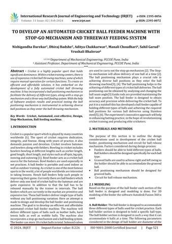
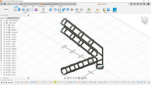
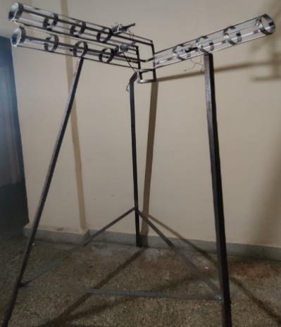
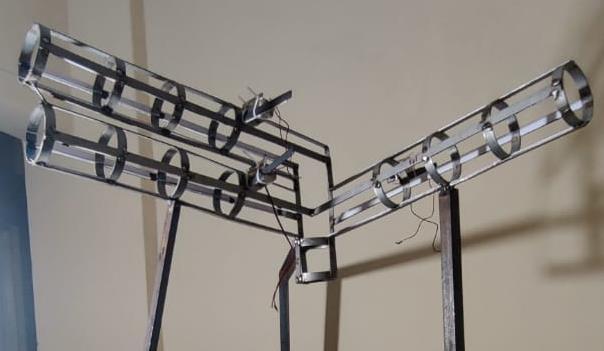
B. Ball Feeder:Theballfeederisdesignedtoaccommodate threedifferenttypesofcricketballs,includingleatherand tennisballs,aswellasgroovedballs.Thethreeballholders, their alignment, and the structural design of the overall feeder, ensuring stability and the ability to withstand the weightof18ballsareconsideredwhiledesigningthefeeder.
a.HolderConfigurationforGroovedBalls
b.HolderConfigurationforLeatherandTennisBalls
Inthefollowingfigurethefinal3Ddesignoftheballfeeder along with it all three-ball holder section (without ball positioningrods)isshown:
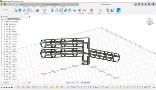
C. Ball positioning rods: The ball position mechanism is crucialforholderdesign,asitalignsthegroovesofgrooved balls for ball throw and swing. Guiding rods are used to positionthegroovedballs,fittingperfectlyinthe1stand3rd grooves.Twoholdershaveopposingguidingroddirections for achieving right and left swings, while the third holder lackssuchamechanism,astheball'spositiondoesn'taffect bowlingvariations.
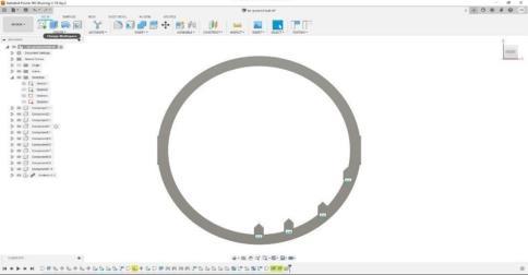
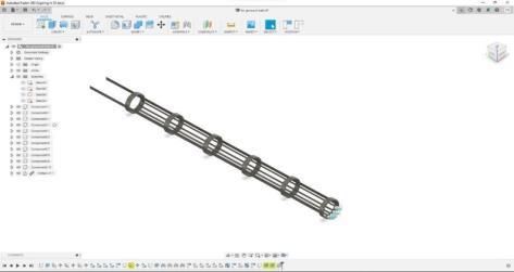
Fig -2: (a)Designofballpositioningrods;(b)placementof ballpositioningrods
Design parameters for the ball positioning rods:
Diameterofball:75mm
Circumferenceofrings:2*3.14*40=251.2mm
Grooveswidthanddepth:2mm
No.ofgrooves:4
Distancebetweentwoadjacentgrooves:6mm.
Maximumnumberofballsineachholder:6
Length of holder from point of ball insertion release mechanism:6*75=450mm
Toleranceof70mmtoaccommodatethespacetoattacha solenoidactuator.
Therefore,totallengthofholder=520mm
The three-way ball feeding mechanism is ingeniously designedtohandleupto18 ballsatonce,makingithighly efficientforcricketpracticesessions.Withinthismechanism, each ball is individually slid into separate hoppers, and notably,twoofthesehoppersareequippedwithspecialized guiding rods. These guiding rods play a crucial role in preciselypositioningtheballs,ensuringthattheirslotsalign perfectly with the rods. As the balls are guided into their desiredorientations,astop-gomechanismcomesintoaction. Thismechanismalsohasprogrammableactuators,givingus complete control over the entire process of stopping and releasingtheballswithexceptionalaccuracy.
The ball release mechanism is part of the ball feeder which is responsible for proper release of balls from their holdersasrequired.Mainfunctionofthismechanismisto ensurethefollowingobjectives:
1. Theballisreleasedbasedonthebowlingtypeselected. 2. Ballisreleasedfromonlyonefeeder.
International Research Journal of Engineering and Technology (IRJET) e-ISSN: 2395-0056
Volume: 11 Issue: 02 | Feb 2024 www.irjet.net p-ISSN: 2395-0072
3. Onlyoneballisreleasedatatime.
Ballreleasemechanismisplacedonthesupportringsofthe ball holder. The position of the solenoid valve of the ball release mechanism is decided based on the total length requiredtoaccommodate6balls.
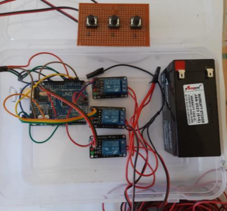
Following are the components used in the circuit of ball releasemechanism:
a.ArduinounoR3–1 b.12Vrelaymodules-3
c.12Vbattery-1 d.12Vsolenoidvalves-3
e.pushbuttons-3 f.zeroPCB
Strokelengthofsolenoidactuator:25mm
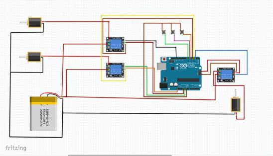
Relay modules and the Arduino must both have a battery connected to get the proper power input. Push buttons shouldbeconnectedtotheArduino'sdigitalinputpins.Relay module pins on the Arduino should be connected. To the relay modules, connect the 12V solenoids. To make these connections,usethecorrespondingwires.Thepushbuttons arelinkedtothedigitalinputpinsontheArduinosothatthe usercandeterminehowthemechanismworks.TheArduino UNOshouldbeprogrammedwiththepropercode.Thelogic forreadinginputfromthepushbuttonsandcontrollingthe relaymodulesappropriatelyshouldbeincludedinthecode. The push button input is read by the Arduino, which then usesthebuttonpressestocalculatetheintendedaction.The Arduinoactivatesthecorrespondingrelaymodulebysetting its output pin to HIGH when the proper push button is pressed.Thesolenoidvalveisturnedonwhen thecurrent from the 12 V battery passes through the closed internal switchoftheactiverelaymodule.Accordingtoitsdesign,the solenoidvalveopensorcloses,permittingorrestrictingthe movement of the ball by enabling or disabling the stop-go actionofthemechanism.TheArduinoswitchestheoutput pinoftheassociatedrelaymoduletoLOWwhentherequired operation is finished. The solenoid valve's current flow is stopped when the relay module's internal switch opens, bringingthemechanismtoanend.ByusingtheArduinoto activateanddeactivatetherelaymodules,thesolenoidstopgomechanismcarriesoutthedesiredstopandgoactionsin response to user input via the push buttons. The solenoid valves and relay modules receive power from the 12V battery,whichenablesthemechanismtooperateasintended.
The design proposed is tested by applying required boundaryconditionsinanalysissoftwarenamelyAnsys The minimumsafetyfactor(perbody)oftheballfeederis2.643 andthemaximumsafetyfactor(perbody)oftheballfeeder is15.
Material: Stainlesssteel
Density: 8E-06kg/mm3
Young's modulus:193000MPa
Poisson's ratio: 0.3
Yield strength: 250MPa.
Ultimate tensile strength: 540MPa.
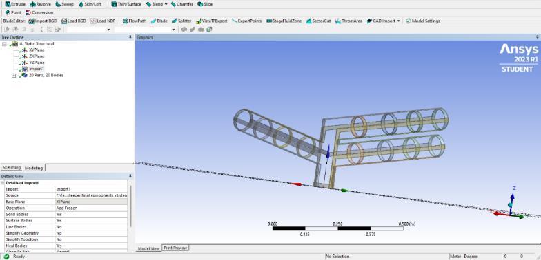
Fig -4: Geometryoffeeder
Force on each holder:
Forcemagnitude:40N.
Xdirection:0N
Ydirection:0N
Zdirection:-40N
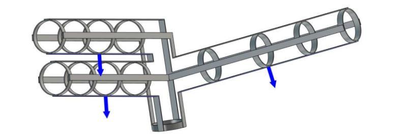
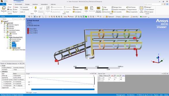
Fig-5: ForcesonFeeder
International Research Journal of Engineering and Technology (IRJET) e-ISSN: 2395-0056
Volume: 11 Issue: 02 | Feb 2024 www.irjet.net p-ISSN: 2395-0072
Von Mises Stress:
TheminimumVonMisesstressoftheballfeederis9.604E06MPaandthemaximumVonMisesstressoftheballfeeder is94.58MPa.
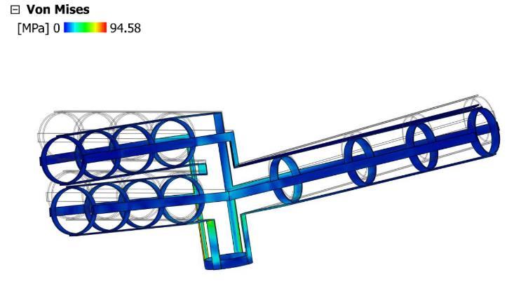
Fig -6: VonMisesstress-feeder
First principal stress:
The minimum first principal stress of the ball feeder is17.45MPaandthemaximumfirstprincipalstressoftheball feederis90.79MPa.
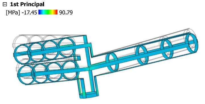
-7: 1st principalstress-feeder
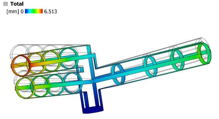
Total Deformation:
Theminimumtotaldeformationoftheballfeederiszeroand themaximumtotaldeformationoftheballfeederis6.513 mm.
Duringphysicaltestingwhenballswereputintothefeeder and aligned and with help of actuator mechanism, it was noticedthatwhenballsaremanuallyslidintothefeederby hand,thealignmentaccuracyreaches approximately84% per50iterations.Ontheotherhand,whenballsarepre-fed intothefeederandsubsequentlycontrolledbytheactuator mechanism,theaccuracyincreasestoaround88%.
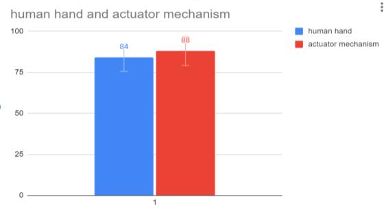
-1: Graphshowsdataofhumanandautomated systemaccuracy.
As mentioned previously, the ball release mechanism governs the controlled release of the ball. To ensure a smoothrelease,thetimeofretractionoftheactuatorneeded to be determined. The following data illustrates the alignmentaccuracyoftheballforvarioustimeintervalsof actuatorretractionover50iterations.Asevidentfromthe data,areleasetimeof0.3secondsyieldsthehighestlevelof accuracy,makingitthepreferredchoice.
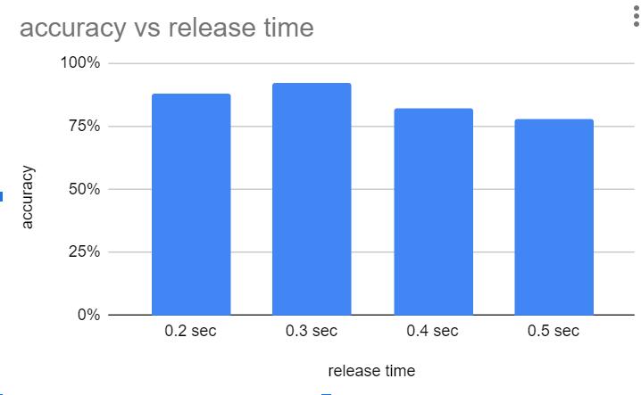
Chart -2: Graphshowsdataaccuracyofballfordifferent releasetime.
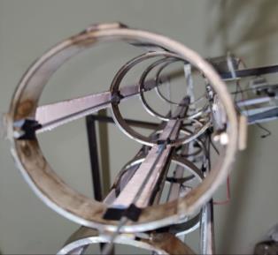
TheballFeederwasfabricatedusingargongasweldingfor stainless steel. The ball positioning rods were fitted using epoxyadhesive,asweldingtheguiderodscaninterferewith the positioning of the ball while moving through the ball feeder. The solution brought up was to use epoxy glue adhesive.
International Research Journal of Engineering and Technology (IRJET) e-ISSN: 2395-0056
Volume: 11 Issue: 02 | Feb 2024 www.irjet.net p-ISSN: 2395-0072
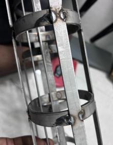
Toachievethedesiredheightforthefeeder,mildsteel(MS) rods were utilized and welded to the feeder. MIG welding wasemployedforthisprocess,utilizingstainlesssteel(SS) rods as filler material. The MS rods served as a sturdy supportstructureforthefeeder.
Threesolenoidswillbeplacedin3holdersofthefeeder,and itwillreleasetheballbasedonbatsmanrequirements.The actualcircuitconstructedbasedonthecircuitdesignisas follows:
a. The3-wayballfeederhasbeenskillfullyengineeredto accommodateatotalof18balls,comprising12ribbed balls equipped with specialized slots for precise positioning. These strategically placed slots facilitate variousballmovements,suchasinswingandoutswing. Furthermore,thefeederincludesslotstoaccommodate bothleatherballsandtennisballs.
b. The integration of circuits within the system ensures efficient control over the ball release, allowing for precise timing as desired. In summary, the project's objectiveshavebeensuccessfullyachievedthroughthe developmentandimplementationofthismechanism.It enablesdiverseballpositionsandacontinuousstream of18deliveries,whichcanbecustomizedforinswing, outswing, or straight deliveries. This remarkable accomplishment provides batterswitha versatileand effectivetrainingtooltoelevatetheirbattingtechniques andoverallperformance.
c. Thisadvancedfeedingsystemoffersacontinuousand streamlined flow of cricket balls, providing an ideal trainingtoolforbatterstorefinetheirtechniquesand enhance their overall performance on the field. Its efficiencyandprecisionmakeitanindispensableasset incrickettrainingsetups,helpingplayerssharpentheir skillsandfacevariouschallengingballorientationswith confidence.
7.
[1] “Wikipedia.”https://www.wikipedia.org/(accessed Jul.26,2023).
[2] Q. Yuan and P. Y. Li, “Self-calibration of push-pull solenoid actuators in electrohydraulic valves,” Am. Soc. Mech. Eng. Fluid Power Syst. Technol. Div. FPST, vol. 11, pp. 269–275, 2004, doi: 10.1115/IMECE2004-62109.
International Research Journal of Engineering and Technology (IRJET) e-ISSN: 2395-0056
Volume: 11 Issue: 02 | Feb 2024 www.irjet.net p-ISSN: 2395-0072
[3] A.Raza,O.Diegel,andK.M.Arif,“Robowler:Design and development of a cricket bowling machine ensuringballseamposition,” J. Cent. South Univ.,vol. 21, no. 11, pp. 4142–4149, Nov. 2014, doi: 10.1007/S11771-014-2409-2.
[4] A.Cork,L.Justham,andA.West,“Three-dimensional visionanalysistomeasurethereleasecharacteristics ofelitebowlersincricket,” Proc. Inst. Mech. Eng. Part P J. Sport. Eng. Technol.,vol.227,no.2,pp.116–127, Jun.2013,doi:10.1177/1754337112447264.
[5] V.B.Bhandari, Machine Design Data Book,2ndEditio. McGrawHill,2019.Accessed:Jul.26,2023.[Online]. Available:https://www.mheducation.co.in/machinedesign-data-book-9789353166304-india
[6] V. B. Bhandari, Design of machine elements. Tata McGraw-Hill,2007.Accessed:Jul.26,2023.[Online]. Available: https://books.google.com/books/about/Design_of_ Machine_Elements.html?id=f5Eit2FZe_cC