
International Research Journal of Engineering and Technology (IRJET) e-ISSN:2395-0056
Volume: 11 Issue: 02 | Feb 2024 www.irjet.net p-ISSN:2395-0072
International Research Journal of Engineering and Technology (IRJET) e-ISSN:2395-0056
Volume: 11 Issue: 02 | Feb 2024 www.irjet.net p-ISSN:2395-0072
Dr.D. Satheesh Pandian1, Mrs.D.Thangamari2, Mr.M.Mohanraj3
1Associate Professor, Dept. of Mechanical Engineering, K.L.N College of Engineering, Sivagangai (D.t), Tamilnadu, India
2Assistant Professor, Dept. of Computer Science Engineering, K.L.N. College of Engineering, Sivagangai (D.t), Tamilnadu, India
3Assistant Professor, Dept. of Mechanical Engineering, K.L.N.College of Engineering, Sivagangai (D.t), Tamilnadu, India ***
ABSTRACT
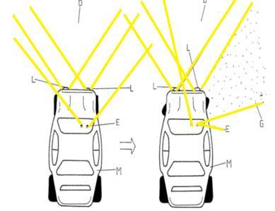
The standard method of steering involves the use of a manually operated steering wheel positioned in front of the driver. This steering wheel is connected to the front wheels through a steering column, which is equipped with universal joints to enable slight deviations from a straight line. Different arrangements can be observed on various types of vehicles. For instance, a tiller or rear-wheel steering may be utilized. Tracked vehicles like tanks typically utilize differential steering, where the tracks move at varying speeds or even in opposite directions to alter the course. The focus of this paper, however, is on front wheel steering, which incorporates movable headlights and the latest interelectronic technology.
Keywords: Movable Head Light, steering system, vehicle safety
Vehicle safety aims to reduce the occurrence of traffic accidents or mitigate the detrimental consequences of accidents, particularly those that impact individuals' wellbeingandphysicalcondition.Safetymechanismshavebeen incorporatedintoautomobilesformanyyears,withcertain features designed specifically to protect the passengers inside the vehicle, while others are meant to safeguard others on the road. The development and production of a steering-controlled Headlight system, designed to enhance the safety of the vehicle. This apparatus pertains to a headlightsetupforautomobiles,specificallydesignedtobe linked to the vehicle's steering system in order to light up theintendedrouteoftravel.
This system comprises of support brackets that can be operated to connect headlight supporting members onto a frame portion of the vehicle. There are linkage means that interconnectthebrackets,allowingthemtomovetogether. Additionally, there are means that connect one of the brackets to the vehicle's connector rod. As a result, the
brackets and headlight members are able to move in relation to the direction of vehicle travel. This device pertains to a headlight setup that is linked to the steering and front wheel assembly of a vehicle in order to ensure that the headlight components and front wheels remain aligned at all times. The steering mechanism enables the driver to navigate the moving vehicle along the road and make desired right or left turns. Moreover, the maneuvering of the vehicle should not demand increased exertion from the driver. Ensuring car safety involves preventing car collisions and reducing the detrimental consequencesofsuchincidents.
In a conventional front wheel steering system, the rear wheels do not rotate towards the curve, thereby limiting the effectiveness of the steering mechanism. Nevertheless, therearwheelsinthesesystemswereonlysteeredby2or 3degrees,withtheprimary goalofaidingthefrontwheels rather than steering independently. While a sophisticated four-wheel steering system for production has not been developed, several experimental prototypes incorporating cutting-edgetechnologieshavebeenconstructedandtested withpositiveresults.
Typically, when vehicles make turns, the tires experience the effects of grip, momentum, and steering input. However, when the vehicle deviates from driving straightahead,thetiresencounterroadgripandslipangle. Tractionensuresthecar'stiresgriptheroadsurface,while momentum propels the car forward in a straight line. The car briefly opposes turning, resulting in the tire losing traction. As soon as the vehicle starts to react to the steering command, lateral forces are produced. The car flips over as the back wheels attempt to mimic the cornering forces produced by the front tires. Due to the time lapse between the control signal and the vehicle's reaction,thisoccurrenceisreferredtoastaillag.Whenthe steeringwheelisturned,thevehicle'sframeswaysandthe rear wheelsoncemoreattempttoalignwith thecornering forcesproducedbythefrontwheels.
International Research Journal of Engineering and Technology (IRJET) e-ISSN:2395-0056
Volume: 11 Issue: 02 | Feb 2024 www.irjet.net p-ISSN:2395-0072
The concept behind all-wheel steering is that when all four wheels are actively steering, the driver needs to provide less input for each steering maneuver. Just like two-wheeldrivevehicles,tiretractioniscrucialforkeeping allfourwheelsincontactwiththeroad.Nevertheless,when thedrivermakesaslightturnofthesteeringwheel,allfour wheelsreacttothesteeringinputs,resultingindriftangles occurringateachofthefourwheels.Thecarreactsfasterto steering commands as the delay in the rear wheels has beenremoved.
The rear wheel steering direction is determined by the prevailing operating conditions. At low speeds, there is a noticeable movement in the wheels, causing the rear wheelstoturnintheoppositedirectionofthefrontwheels. Additionally, this feature simplifies the process of maneuvering the vehicle, especially when navigating throughnarrowparkingspaces.
The back wheels of a car with four-wheel steering do notturninthetypicalwayastheyareengineeredtofollow the trajectory established by the front wheels on the pavement. As a result, the chances of running into an obstacle are greatly reduced. When operating a vehicle at high velocities and making minor adjustments to the steering, the front and rear wheels will both rotate in unison. As a result, the car moves laterally in a manner similartoacrab,insteadoftracingaseamlesscurvedpath.
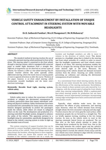
This maneuver is advantageous for the vehicle when changinglanesonahigh-speedhighway.Theeliminationof thecentrifugalforcereducesbodyrollandcorneringforces on the tire, improving the stability of the vehicle and making it easier to control, thus enhancing safety. Throughout this study, our primary objective has been to reduce the vehicle's turning radius, improve safety measures to prevent nighttime accidents, and optimize the vehicle's parking capabilities in designated areas. We have meticulously selected pertinent sources to bolster our research endeavors. Numerous individuals have presented their viewpoints on these matters. The alignment of the headlightwiththewheelisdisplayedbelow.
Saket Bhishikar, et.al developed a four-wheel steering system due to the fact that the rear set of wheels remain fixed in a forward direction and do not actively contribute to steering control. An inventive 4 wheel steering design has been created to incorporate a mechanism capable of alteringthesteeringoftherearwheelsinbothin-phaseand counter-phase,dependingontheturningandlanechanging conditions in relation to the front wheels. This advancementsignificantlyimprovesthemaneuverabilityof a sedan in accordance with its speed. This system aids in swift lane changes and improved maneuvering around corners.
It addresses the challenges encountered during sharp turns by decreasing the car's turning circle radius, enhancing maneuverability and control at high speeds, ultimatelyachievingneutralsteering.
In 2009, Jack Erjavee stated that when the vehicle is traveling at a high speed and requires slight steering adjustments,itisnecessarytoturn boththefrontandrear wheels in the same direction. Consequently, the vehicle maneuvers in a sideways motion resembling that of a crab instead of following a smooth curved trajectory. This behavior proves advantageous for the car while executing lane changes at high velocities on a highway. Enhancing stability by reducing the centrifugal effect and minimizing body roll and cornering force leads to improved control, making it easier and safer to maneuver.This article providesdetailsonacrucialaspectofafour-wheelsteering system, which is the control of the drive angle at both the frontandrearwheels.
In their study, K. Lohith, et.al concluded that the implementation of four-wheel steering represents a significant endeavor by automotive design engineers to achieve a steering system that is close to neutral. Maruti Suzuki 800 is regarded as a benchmark vehicle in their paper. The primary objective of this endeavor is to synchronize the rear wheels with the front wheels in an opposite phase. To accomplish this objective, a mechanism was devised that comprises of two bevel gears and an intermediate shaft. This mechanism not only transfers 100%torque but alsorotatesthe rear wheelsinanout-ofphasemanner.
In their study, Dilip S Choudhari1 et.al reach the conclusion that the steering of both the front and rear wheels can be adjusted based on the vehicle's speed and the amount of space available for turning. The primary objective is to ensure that steering the vehicle does not demand excessive effort from the driver. The Quadra steer steering system provides a 21% decrease in the turning radius. If a vehicle can perform a U-turn within a 25-foot area, Quadra steer enables the driver to accomplish it
International Research Journal of Engineering and Technology (IRJET) e-ISSN:2395-0056
Volume: 11 Issue: 02 | Feb 2024 www.irjet.net p-ISSN:2395-0072
within approximately 20 feet. Hence, the four-wheel steering system possesses the ability to navigate corners, respond to steering inputs, maintain stability on straight roads,facilitatelanechanges,andenhancemaneuverability atlowspeeds.
ManishaVMakwana,alongwithothers,constructedthe hardware for a mobile Headlight System designed for motorvehicles.Theutilizedsystemincorporatesarackand pinionarrangement,enablingthetransmissionofpowerto the optical axes where the headlights are positioned. Consequently, when the tie rod arms are manipulated by the steering arm, both the wheels and the headlights are subjected to a predetermined motion. This mechanism assistsinadjustingthepositionoftheheadlightstotheleft or right based on the need during turns, thereby aiding in minimizing nighttimeaccidentson windingroadsandhilly terrains.
Gadhave Yogesh V, along with others, presented the "Steering Controlled Headlight Mechanism" that functions as headlights thatadjust direction based on steering input. Itwasnotedthatrotatingthesteeringwheeltotherightby aspecificanglecausestheheadlightstotilttotherightbya certain degree, thanks to various linkages positioned in relation to the steering wheel as previously explained. Similar characteristics can be noted when the steering wheelisrotatedtowardstheleft.
ThestudybyAjayR.Pawar,Mandhareet.alfocusesona system that can be implemented in various types of fourwheel vehicles, trucks, trailers, etc., without causing financialstrainontheuser.However,itsuniquefeaturelies in its adaptability based on the vehicle's turning radius. During the night, a significant expansion in the observable region is noticed. The developed headlight system offers a significant benefit in its exceptional adaptability, allowing for seamless integration into a wide range of vehicle designs. Additionally, the system is cost-effective, uncomplicated,andstraightforwardtoassemble.
The selection of materials is a crucial stage in the design process of any tangible item. When it comes to product design, the primary objective of material selection is to reduce expenses while achieving the desired product performance targets. The process of systematically choosing the most suitable material for a specific application commences by evaluating the properties and costsofpotentialmaterials.
Mildsteelcanbechosenhere,withtherationaleforits selectionoutlinedbeneath.Mildsteel,alsoknownasplaincarbon steel, is widely used due to its affordable price and
satisfactory material properties for various applications, surpassing those of iron. Low-carbon steel is composed of around 0.05–0.3% carbon, which gives it the properties of being easily shaped and flexible. Mild steel exhibits a modest tensile strength, yet it is cost-effective and pliable; carburizing can enhance its surface hardness. Large quantities of steel are frequently utilized, particularly as structural steel, due to its high demand. Mild steel has a densityof 7850kg/cm3 anda Modulus ofElasticityof 210 GPa(30,000,000psi).
• Cast iron has a lower melting point in comparison to steel.
• Steel is produced by incorporating a regulated quantityofcarbon.
•Steel isgentle,moredifficulttomold,andpossessesa relativelyhighviscosity.
•Steelremainsintactwhensubjectedtobendingforces.
•Steelpossessesahigherleveloftensilestrength.
•Steelissuperiorintension.
3.3 SELECTION OF BEARINGS
A ball bearing is a form of rolling-element bearing that employsballstoupholdthegapbetweenthebearingraces. The primary objective of a ball bearing is to diminish rotational friction and provide assistance for both radial and axial loads. Choose a footstep with a minimum inner diameterof20mmanda radialloadcarryingcapacityofat least100kg.Theballbearingspecificationis25x50x15mm.
Thebearingisequippedwithrubbersealsonbothends to retain lubricant and prevent contaminants from entering. It is pre-lubricated by the manufacturer, eliminating the need for any extra lubrication. This sealed ballbearingwithadeepgrooveisdesignedforapplications requiring both radial and axial loads, as well as high running accuracy at elevated rotational speeds. Various applicationsencompassclutches,transmissions,gearboxes, compressors, pumps, turbines, as well as printing and textilemachinery,amongotherexamples.
Inthisinstance,wearechoosingthealloywheelsforthe manufacturing process. Alloy wheels are crafted from a blend of aluminum or magnesium. Alloys consist of a combination of metal and additional elements. Typically, they offer increased strength compared to pure metals,
International Research Journal of Engineering and Technology (IRJET) e-ISSN:2395-0056
Volume: 11 Issue: 02 | Feb 2024 www.irjet.net p-ISSN:2395-0072
which tend to be softer and more malleable. Aluminum or magnesiumalloysaregenerallylighterthansteelwheelsof the same strength, offer superior heat conduction, and frequently result in enhanced aesthetic appeal. Steel, the most frequently utilized material in wheel manufacturing, is a combination of iron and carbon. However, the designation"alloywheel" typicallyreferstowheelscrafted fromnonferrousalloys.
The operation of the final drive and differential assembliesinthelivefrontaxlesmirrorsthatofrearaxles. Gear ratios designed to boost engine torque will match those found in the rear axles of the vehicles. When the vehicle moves in a straight line, the inner and outer axle shafts are aligned. If the front axle is connected to the power train, the inner axle shaft will propel the cv joints. Thesejointswillthenrotatetheouteraxleshafts,whichare connectedtothewheelhubs.
As the steering arms and rods rotate the knuckles, the axle shafts will experience flexion at the CV joints. While making turns, the CV joint will consistently provide a seamless and steady transmission of torque. The steering linkagessimultaneouslyadjustthesteeringknucklestothe appropriateanglefortheturn.
The purpose of this component is to transfer power from the live axles and can also serve as a steering mechanism. Its primary function is to facilitate the smooth rollingofthewheelsontheroad.Dependingonthesteering adjustments,thewheelcanbeeithertoe-inortoe-out.
Currently, all vehicles operate using a two-wheel steering system. However, it has been demonstrated that theconventionaltwo-wheelsteeringsystemislessefficient when compared to the four-wheel steering system. Therefore,thisstudyaimstohighlightthesuperiorityofthe four-wheel steering system over the two-wheel steering system in terms of turning radius. Typically, a vehicle that possesses a larger turning radius encounters difficulties when it comes to parking and maneuvering at low speeds. However, passengers tend to favor vehicles with an extended wheelbase and wider track width as it provides enhancedcomfortduringtravel.
In this situation, the utilization of four-wheel steering will prove beneficial by reducing the turning radius for a vehicle with an extended wheelbase. The study involves modifyingabenchmarkvehicletoincorporateafour-wheel steeringsystemwithoutalteringitsoriginaldimensions.To achieve reduction, a mechanism has been constructed
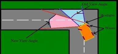
wherein the rear wheels are turned in the opposite direction to the front wheels. This affects the driver's visibility during nighttime, making it difficult for them to accuratelyassessroadturns,particularlyonsharpbendsin hilly regions, due to the occurrence of road accidents. Drivinga four-wheelercan bechallenging, especiallywhen navigating sharp turns. This particular model assists drivers by automatically adjusting the focus of the headlights based on the direction of the steering wheel. Adaptive headlights are designed to respond to the car's steeringsystemandautomaticallyadapttoprovideoptimal illuminationfortheroadahead.Whenthecarturnsleft,the headlights adjust their angles accordingly to the left. Insteadofrelocatingtheheadlights,reflectorsareinstalled internally on both sides of the headlamp housing. These reflectorsareadjustedinordertoguidethebeam.
The reflectors are moved in the same direction as the vehicle'smovement,andthepowerneededforthismotion istransferredthroughhydrauliclinkages.
Our study aims to demonstrate the superiority of thefour-wheelsteeringsystemoverthetwo-wheelsteering systeminrelationtoturningradius.
Inthisstudy,weexaminetheapplicationofafourwheel steering mechanism on a benchmark vehicle, while keepingitsdimensionsunchanged.
Wehavesuccessfullydecreasedtheturningradius incomparisontoalternativesteeringsystems.
Adjust the headlights while making a sharp turn withthesteeringwheel.
Westrivetomaintaintheparallelalignmentofthe headlight beam with the road as much as we can while makingaturn.
Enhancing the driver's visibility during nighttime toenablebetterjudgmentofroadcurves.
It is crucial to take measures to avoid road accidentsduringnighttime,particularlywhenencountering sharpturns,especiallyinhillyregions.
International Research Journal of Engineering and Technology (IRJET) e-ISSN:2395-0056
Volume: 11 Issue: 02 | Feb 2024 www.irjet.net p-ISSN:2395-0072
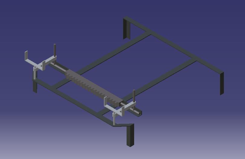
Fabrication plays a crucial role in every paper, as it involvestransformingourideasintotangiblemodels.Inthe context of this particular endeavor, the fabrication process focuses on creating a four-wheel steering system. Our papernecessitatestheattachmentofnumerousitemstothe frame. The fabrication process involves the utilization of multiplemachines.
The implementation of a four-wheel steering system withadjustableheadlightsisaccomplishedthroughaseries ofprocesses,whichinclude:
Gascutting
Grinding
Drilling
In this paper, the tri-star clamp is employed to connect the wheels in unison. Ascending stairs becomes arduous whenusingasinglewheel.
The wheels are linked to the arms of the clamp, and as the Tri-Star setup ascends the stairs, it rotates upon reaching the stair edge. The Tri-Star undergoes fabrication throughthegascuttingprocess.Thewheelsarepositioned betweenthetwoclampsutilizingaircooledarcwelding.
At first, we secured the live axle and the stubs during the initial phase of assembly. Subsequently, we drilled12mmholesattherearendoftheframetofacilitate theattachmentoftheliveaxles.Thestubsareconnectedto the tyresetsfollowing theaxles.The tub is responsible for providing both steering and power transmission to the wheels.
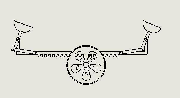
Subsequently, clamps are positioned to secure the sungearsthatareweldedatthecenteroftheframe.
Thesungearpositionisconnectedtotwotierods fromeachsideofthestub,allowingustosecurethetierods tothesungearswith10mmlongthreadedbolts.
Theproceduredescribedisalsocarriedoutforthe lowersungear.
The tie rod is connected to tie rod ends on both sides,whicharesecuredtothesungearsattherearend.
Two tie rods extend from the front wheel C-clamp and are secured to the steering column using elongated fullythreadedbolts.
The journal bearing is utilized to firmly secure the shaftresponsiblefortransmittingthesteeringmotionfrom thefronttotherearwheels,ensuringasolidconnection.
Ultimately,puttogetherthetiresets.
Following the completion of the final assembly frame, it undergoes testing. Subsequently, measurements such as the turning radius before and after meshing are taken,alongwiththesunandplanetgearmeshing.
Subsequently,theheadlightsarepositionedonthe wheel clamps in an L-shaped configuration, representing the most basic type of adjustable headlamps based on the vehicle'ssteering.Thesteeringenablesthemtorotateupto a maximum angle of 120 degrees. The connections are established based on the automobile's design and requirements.
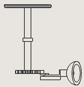
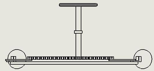
Thispatentpertainstoavehicleheadlamp,specificallya mobile vehicle headlamp mechanism that provides illuminationinthedirectionthevehicleisturning.
Typically, conventional headlights and auxiliary lights are permanently positioned at a specific angle on the front of a vehicle's body to illuminate the area ahead of the car. Hence, when the steering wheel is turned to alter the car's traveldirection,thefront-wheelalignsitselfatananglethat corresponds to the degree of the steering wheel's turn in relation to the car's original direction of travel. Hence, the vehicle's chassis shifts towards an unilluminated path, thereby presenting a hazard as it transforms into an obscureregion.
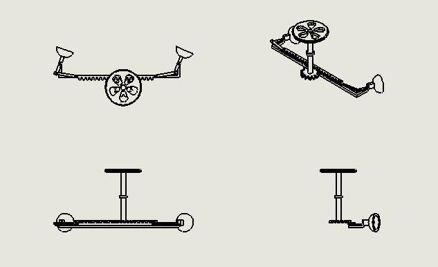
The objective of the present invention is to offer a unique car headlight device that automatically illuminates the direction in which the car is turning when the car is being turned. To be more precise, the movable car headlightmechanismofthecurrentinnovationconsistsofa vertical main axis that is securely attached to a bracket positionedonasuitablesectionofthecar'sbody.Thereisa receiving table that the main axis passes through, and a rotating body with balance weights on both sides is connectedtothemainaxis.Thisbodyiscapableofrotating and rests on the receiving table. Additionally, there is a casing located at the upper end of the main axis, which supports a lamp at its rear part and is also rotatable. The casing is linked to the rotating body in a manner that enables independent upward or downward movement of therotatingbodywhilealsoco-rotatingwiththecasing.
The contact between the receiving table and the rotatingbodyisdesignedintheshapeofaV-shapedwedge. This allows the rotating body to rise up from the contact surfaceasitrotates,thankstothecentrifugalforceexerted bythebalanceweightscausedbythecar'smovement.Asa result, the casing with a lamp is rotated, and the rotating body receives a restoring force from the potential energy accumulated by rising up the V-shaped surface of the receivingtable.
SOLIDWORKS,createdbyDassaultSystems,standsasa premier CAD/CAM/CAE software globally. As a robust modeling platform, it seamlessly integrates 3D parametric
International Research Journal of Engineering and Technology (IRJET) e-ISSN:2395-0056
Volume: 11 Issue: 02 | Feb 2024 www.irjet.net p-ISSN:2395-0072
capabilities with 2D tools, while also encompassing the entire design to manufacturing workflow. In addition to offering a glimpse into the design content, the package fosters cooperation among businesses and gives them a competitiveadvantage.
Furthermore, within the drawing mode of Solidworks, it is possible to generate 2D drawing views alongside the creation of solid models and assemblies. These drawing views encompass a range of options such as orthographic, section,auxiliary,isometric,anddetailviews.
Solidworks utilizes parametric design principles in solid modeling. This software offers a method for automating mechanical design through solid modeling technologyandvariousfeatures.
The fundamental distinction between solidworks and conventional CAD systems lies in the fact that the models generatedinsolidworksaretangible3Dsolids. Solidworks modelstheentiresolid,unlikeother3Dmodelersthatonly depict the surface boundaries of the model. This not only enables the generation of lifelike geometry, but also ensures precise model computations, particularly for mass characteristics.
Solid works model geometry is influenced by dimensions like angle, distance, and diameter. By establishingrelationships,parameterscanbeautomatically computed depending on the values of other parameters. When altering the measurements, the complete model structure can be adjusted in accordance with the establishedrelationships.
The models are constructed by using Solid Works with object features. These features possess a level of intelligence, as they possess knowledge about their surroundingsandcanadaptinapredictablemannertoany alterations. The user is prompted to provide specific information for each feature, depending on its type. For instance, a hole requires the user to input its diameter, depth,andplacement,whereasaroundfeaturerequiresthe usertospecifyitsradiusandtheedgestoberounded.
Solid works operates as a completely associative system,ensuringthatanymodificationsmadetothedesign model at any stage of the development process are reflected across all engineering deliverables such as assemblies, drawings, and manufacturing data without manual intervention. Associatively facilitates the
implementation of concurrent engineering by promoting flexibility, allowing for modifications without any negative consequencesatanystageofthedevelopmentprocess.This empowers downstream functions to share their insights andexpertiseatanearlystageinthedevelopmentcycle.
Parametricmodeling'spowerliesinitscapacitytomeet essential design parameters as a solid model progresses. The notion of capturing design intent is rooted in integrating engineering expertise into a model. The objective is accomplished through the establishment of characteristics and component connections, as well as the implementationofthefeaturedimensioningplan.
6.6
International Research Journal of Engineering and Technology (IRJET) e-ISSN:2395-0056
Volume: 11 Issue: 02 | Feb 2024 www.irjet.net p-ISSN:2395-0072
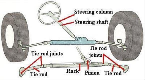
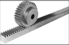
Arackandpinionisaformoflinearactuatorconsisting of two gears that transform rotational movement into linear motion and vice versa. The pinion, a circular gear, meshes with teeth on a linear bar known as the rack. By applyingrotationalmotiontothepinion,therackmovesin relation to the pinion, effectively converting the rotational motion into linear motion. Each set of complementary involute profiles corresponds to a fundamental rack. This fundamental rack represents the profile of the complementary gear with an infinite pitch radius (i.e. a toothed straight edge). Rack and pinion assemblies are commonlyemployedinbasiclinearactuators,transforming the rotational movement of a manually or motor-driven shaftintolinearmotion.Theactuator'sentireloadisborne bytherack,resultinginatypicallysmalldrivingpinion.
This design choice allows for a reduction in torque requirements due to the gear ratio. However, the force or torque involved may still be significant. Therefore, it is customary to incorporate a reduction gear, either in the
form of a gear or worm gear, immediately preceding the actuatortofurtherreducethetorque.Rackgearspossessa superior ratio, consequently necessitating a larger driving torque in comparison to screw actuators. Within this undertaking, when pressure is exerted on the pedal, it is transmittedtothespringthatisconnectedtothebottomof therack.Subsequently,therackmovesandsimultaneously causesthepiniontorotateaswell.
Intherealmofconstruction,framing,alsoreferredtoas light frame construction, is a method of building that revolves around the utilization of structural elements, commonly known as studs. These studs serve as a sturdy framework to which both interior and exterior wall coveringsareaffixed.
Additionally, this framework is further reinforced by horizontal joists and sloping rafters or pre-fabricated roof trusses, which are concealed by a range of sheathing materials.Light frame material sizes vary from 38 mm by 89mm(1.5by3.5inches,alsoknownasatwo-by-four)to5 cm by 30 cm (two-by-twelve inches) in terms of crosssection dimensions, with lengths ranging from 2.5 m (8
International Research Journal of Engineering and Technology (IRJET) e-ISSN:2395-0056
Volume: 11 Issue: 02 | Feb 2024 www.irjet.net p-ISSN:2395-0072
feet) for walls to 7m (20 feet) or longer for joists and rafters.
The ride on curved roads, particularly on ghat roads,isbothsmoothandsafe.
Offersaliberatingexperienceforthedriver'smind.
Ensuresthecountry'sroadsremainaccident-free.
This safety measure has been enhanced and implementedinautomobiles.
User-friendly..
Theamountofmanualpowerneededisreduced.
Fixingtheissueisastraightforwardtask.
Itissimpletoreplacecomponents.
Thereisnorequirementforexcessivelubrication.
The steering-controlled headlight system can be implemented in large vehicles like buses and trucks, primarilyusedonsteepandwindingroads.
Tailored for installation in buses that operate on mountainousghatroads.
This mechanism can be installed in various commercial vehicles including Maruthi, Ambassador, Fiat, Mahindra,Tata,andmore.
To develop the design of our steering box's rack-pinion mechanism, we focus on selecting the rack and pinion that will result in a larger sideways movement of the wheels when the steering wheel is turned. Another initial
consideration is that both the rack and the pinion should havematchingmodulusandbemadeofthesamematerial. AnappropriatematerialforthesecomponentsisSAE1045 steel,knownforitseaseofmanufacturing.
Ultimatetensilestrength(Sut)=625N/mm2.
Assumptions:-
Numberofteethonpinion=12
Numberofteethonrack=28
Pitchlinevelocityofpinion=0.5m/sec.
Tangentialforceonpinion=600N.
Results:-
Standardmodulem=2mm
Hencedimensionofspurpinion:
Dp=Zp*m=12*2=24mm
B=15xm=15*2=30mm
Pressureangle=200
Addendum=1m=2mm
Deddendum=1.25*m=2.5mm
Pitch(p)=6.0283mm
Wehaveapinionwithadiameterof24mm, T=105.948*12=1.27136Nm
This is the torque in the pinion which is transmitted throughthesteeringcolumn.
Thereforethemovementratiois12.47:1
Theoutputloadwillbe:
F=2xMRxF==2x20x12.47=498.8N
Loadtransmittedtothetierodsis498.8N.
According to the objectives, we have developed a cutting-edge four wheel active steering system featuring movable head lights. This mechanism is not only feasible for production, but also highly effective in achieving neutral, in-phase, and counter-phase rear steering in relation to the front wheels. This particular system enhances cornering performance and facilitates quick lane
© 2024, IRJET | Impact Factor value: 8.226 | ISO 9001:2008 Certified Journal | Page785
International Research Journal of Engineering and Technology (IRJET) e-ISSN:2395-0056
Volume: 11 Issue: 02 | Feb 2024 www.irjet.net p-ISSN:2395-0072
changes at high speeds. It resolves the issue encountered during sharp turns. Even when traveling at high velocities, it enhances maneuverability and control by reducing the turning circle radius, similar to neutral steering. Furthermore,thesesystemsarenotonlypracticalandcosteffective,buttheircomponentsarereadilyaccessibleinthe market as well. The installation process for the system is straightforward,anditislightweight,makingitefficientfor implementation in all areas of automobiles. The inclusion ofheadlightsasamandatoryrequirement,coupledwiththe added advantage of turn signals, serves to decrease accidents during nighttime in areas with sharp turns and hills,ultimatelycontributingtothecreationofaccident-free roads nationwide. It has been discovered that when the steering wheel is turned in either direction, the headlights are adjusted accordingly through the use of a rack and pinionmechanism.
[1] Dilip S Choudhari, “Four wheel steering system for future”, International Journal Of Mechanical Engineering and Robotics Research, ISSN 2278 –0149, Vol. 3, Page No 383-387, Issue 4, October 2014.
[2] N.Laxmi, B.AnilKumar, D.Kiranvarma, “Design and Fabrication of A Steering Controlled Headlights in Automobile”, International Journal & Magazine of Engineering, Technology, Management and Research, volume 13, issue 17, Page No 98-102, July 2015,
[3] Ajay R, S. Salekar, U. Mandhare, Sachin D, Sanket S, “Design And Fabrication Of Movable Headlight System” International Journal of Advance Engineering and Research Development(IJAERD), Volume 4, Issue 5, Page No 254-259, May -2017, PISSN(P):2348-6406
[4] J.B. Jiang, C.F. Cheung, S.To, K.W. Cheng, H. Wang, W.B. Lee “Design and fabrication of free form reflector for automotive headlamp” 2nd International Conference on Power Electronics Systems and Applications : Hong Kong, 12-14 November2006,p.220-224.
[5] Gadhave Yogesh V, Jadhav Chakradhar R, Aher Ravindra T, Sonawane Umesh A, Mali Praveen K, “Front Wheel Steering With Movable Head Lights”,IJARIIE,Vol-3,Page No 1623-1628, Issue-3 2017,ISSN(O)-2395-4396
[6] Hiroaki Okuchi, Kunio Ohashi, Yuji Yamada, Yoshiyuki Miki “Automatic optical-axis adjusting device for automatically adjusting directions of optical axes of front lights with respect to steering
angle of steering wheel” Dec 30, 2003,US6671640 B2.
[7] Sawalha,S.A.,Abu-Mansour,T.M.,&Al-Salem,N.M. Steering Speed Suspension Device (Triple" S" device),toPreventBurnouts–TafheetPhenomena.
[8] Masanori Kondo, Kunio Ohashi, Yuji Yamada, Yoshiyuki Miki, “Automatic optical-axis adjusting device for automatically adjusting directions of opticalaxesoffromlights”,10Feb2004,US6688761 B2
[9] K.Lohith,Dr.S.R.Shankapal,&Mr.H.MonishGowda “Development of Four Wheel Steering System for a Car,” SAS Tech Journal, vol. 12, pg. 90-97, Issue 1, April2013.
[10] Dr. Kirpal Singh “Automobile Engineering” Standard PublishersDistributors,vol.1,12thEdition,2011.
[11] V. B. Bhandari “ Design of Machine Elements” McGraw Hill Education India Pvt. Ltd., vol. 3, 11th Edition,2013
[12] Manisha V Makwana, Akshay Shah, Shankar Rahul and Ajay M Patel, et. all “Design and Manufacture of Movable Headlight System in Automobile”, International Journal of Innovative and Emerging Research in Engineering, e-ISSN: 2394 –3343,Volume1,PageNo12-16,Issue2,Dec2014
[13] Saket Bhishikar, Vatsal Gudhka, Neel Dalal, Paarth Mehta,SunilBhil,A.C.Mehta,”DesignandSimulation of4WheelSteeringSystem”,InternationalJournalof Engineering and Innovative Technology (IJEIT), Volume3,Issue12,PageNo351-367,June2014.
[14] Ramkumar, C., Kumar, H. P., & Krishnaprasanth, S. EAACM: Enhanced Ack aware clustering mechanism for energy efficient and secure routing in wireless sensornetworks.
[15] Chi on-dong lin, “Steering wheel controlled car light piloting system”, A International Journal of Innovative and Emerging Research in Engineering Volume1,pageno354-367,Issue2,2014-16.
International Research Journal of Engineering and Technology (IRJET) e-ISSN:2395-0056
Volume: 11 Issue: 02 | Feb 2024 www.irjet.net p-ISSN:2395-0072


Dr.D.Satheesh Pandian attained his B.E. in Mechatronics Engineering, M.E. in Industrial Engineering and Ph.D in Mechanical Engineering. He is affiliated with K.L.N College of Engineering as Associate Professor. His research interests are Mechatronics, Robotics, AutomationandImageProcessing.

Mrs.D.Thangamari completed her B.E. in Computer Science Engineering, and M.E Computer Science Engineering, She is affiliated with K.L.N.College of Engineering as Assistant Professor. Her research interests are Artificial Intelligence, Machine Learning and Robotics.
Mr. M. Mohanraj completedhisB.E.in Mechanical Engineering, and M.E. in Engineering Design. He is affiliated with K.L.N.College of Engineering as Assistant Professor. His research interests are Mechanical component design,RoboticsandAutomation.