
International Research Journal of Engineering and Technology (IRJET) e-ISSN: 2395-0056
Volume: 11 Issue: 02 | Feb 2024 www.irjet.net p-ISSN: 2395-0072
International Research Journal of Engineering and Technology (IRJET) e-ISSN: 2395-0056
Volume: 11 Issue: 02 | Feb 2024 www.irjet.net p-ISSN: 2395-0072
Darshitkumar P. Panchal1 , Vimal R. Patel2
Automobile Engineering Department, L.D. College of Engineering, Ahmedabad, Gujarat, India
Abstract - The environmental issues continue to rise and that forces automobile engineers to develop new concepts to lower fuel consumption and emission levels. This study focuses on the application of aerodynamic enhancement on heavy articulated trucks and investigates the effectiveness of novel aerodynamic trailer design with the combination of cab roof deflectors to minimize drag at the trailer head. Complete model designed using computer graphics and analyzed by computational fluid dynamic (CFD) for each configuration, to optimize class 8 vehicle structure. The test results reveal that early flow separation, pressure difference, and high base wake regions are primary contributors to high drag value. Analysis demonstrates the use of a novel venturi passage design with the combination of cab roof deflectors prominently reduces 17.38% drag coefficient compared with a conventional trailer. Notably, implementation of this combination approach results in a 14% increase in drag performance compared to vehicles that only feature cab roof deflector. These findings will be potentially helpful in the field of Automotive to enhance fuel efficiency and sustainability of heavy commercial vehicles.
Key Words: Fuel Consumption, Aerodynamics, Computational Fluid Dynamics, Venturi Passage, Drag Reduction.
Fuel consumption in the automotive sector has increased dramatically,andheavycommercialvehiclesarethemajor contributor to the high economic loss experienced by the nation.Thesignificantimpactthatheavy-dutyvehicleshave onthetotalamountoffuelusedonroads,witharticulated trucksbeingespeciallyimportantinsuchscenarios,which subsequentlyleadstoconsiderableamountsofairpollution [1].Itisimportanttoanalyzeandputnewmethodsthatwill potentiallyimprovefuelefficiency.
Aerodynamic improvement is one of the most important methodswhenitcomestofuelsaving,accordingtorecent studiesonfuelreductiontechniquesfortrucks.About52% ofthefuelisusedbyalargecommercialvehicletravellingat 100 km/h to provide the power needed to overcome aerodynamicdrag.Thatsignificanteffectisairdragafter90 km/honheavycommercialvehicles[2].Theseclass8trucks travelbetween150,000and200,000milesannually,making their fuel demand high in the automotive industry [3]. Because of its high mileage, any small decrease in
aerodynamicdragwillleadtofuelsavingsandareductionin emissionsofcarbondioxideandotherpollutants.Thereare still a lot of opportunities for improvement, especially by aerodynamicdragreduction.
Despite a number of drag-reducing devices including side skirts,cab-rooffairingsandvanes,baseflaps,gapseals,boat tails,andunderbodyfairings,havebeenresearchedinthe literatureforheavycommercialtrailertrucks[4-8]thereis still a significant research gap when it comes to modifications that are specifically designed to increase aerodynamic performance at the trailer body. However, Clientdemandsforthemaximumvolumecapacityoftrailers havesloweddownthedevelopmentoftrailermodifications for better aerodynamic performance. As a result, the installation of components to optimize the truck cab's aerodynamic performance became the manufacturer’s primary focus [9]. In order to close this research gap, the purposeofthispaperistoexaminehow effectivelya new aerodynamictrailer design will reduceaerodynamic drag. Through Computational fluid dynamics (CFD), the effectiveness of these designs in combination with traditionaldragreductiontechniquesisstudied.
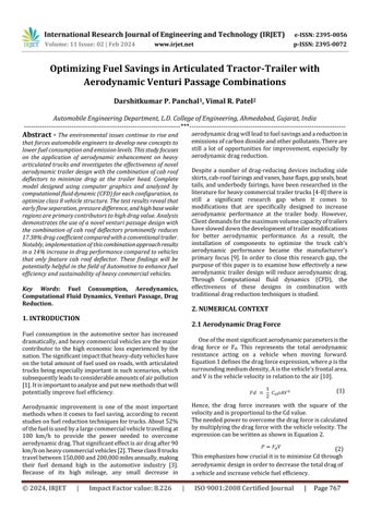
Oneofthemostsignificantaerodynamicparametersisthe drag force or Fd. This represents the total aerodynamic resistance acting on a vehicle when moving forward. Equation1definesthedragforceexpression,whereρisthe surroundingmediumdensity,Aisthevehicle'sfrontalarea, andVisthevehiclevelocityinrelationtotheair[10].
(1)
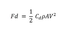
Hence, the drag force increases with the square of the velocityandisproportionaltotheCdvalue. Theneededpowertoovercomethedragforceiscalculated bymultiplyingthedragforcewiththevehiclevelocity.The expressioncanbewrittenasshowninEquation2.
(2)
ThisemphasizeshowcrucialitistominimizeCdthrough aerodynamicdesigninordertodecreasethetotaldragof avehicleandincreasevehiclefuelefficiency.
International Research Journal of Engineering and Technology (IRJET) e-ISSN: 2395-0056
Volume: 11 Issue: 02 | Feb 2024 www.irjet.net p-ISSN: 2395-0072
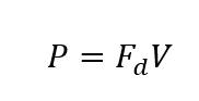
According to Bernoulli, the equation is essential to the studyoftheairflowssurroundingavehicle.Therelationship between air speed and pressure at a specific point is providedbythisequation,wherepisthestaticpressure,ρis the air density, and V is the air speed, is preferred for an aerodynamicanalysis[10].
(3)
Here, the sum of the two terms is constant so that more pressure generates the lower air velocity, and the lower pressure results in the high air velocity at the same spot. This Venturi effect can be utilized for drag reduction by providingasmoothflowofairstreamsoverthevehiclebody.
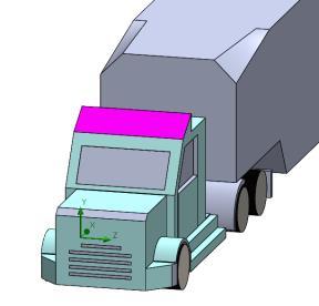
Thecompletearticulatedtractor-trailerwasconfiguredand analyzedusingSolidworks 2022andthecompletevehicle includingcabin,trailer,tyres,andchassiscomponentswas assembled using CAD with high precision to ensure the actual representation of the articulated truck. The dimensions of the articulated truck lorry are as follows, lengthoftrailer=15m(excludingtruckcab),width=3.07m, height=4m(includingthetruckcab),frontalareaofcontact =11.16m2. This 1:1 scale model represents typical heavy commercialvehiclesofEuropeanandAmericantruckswhich isshowninFigure1.Thiswasa6axleheavyloadingvehicle with a 1.2m gap between cabin and trailer. In order to replicatereal-worldconditions,thewindtunnelapparatus hadaclosed-loopdesignwithversatileairflowparameters controlsusingCFDairflow.Computationaldomainsetupin such a way that different conditions can be observed including,basewake,airstreamlines,andflowseparation.
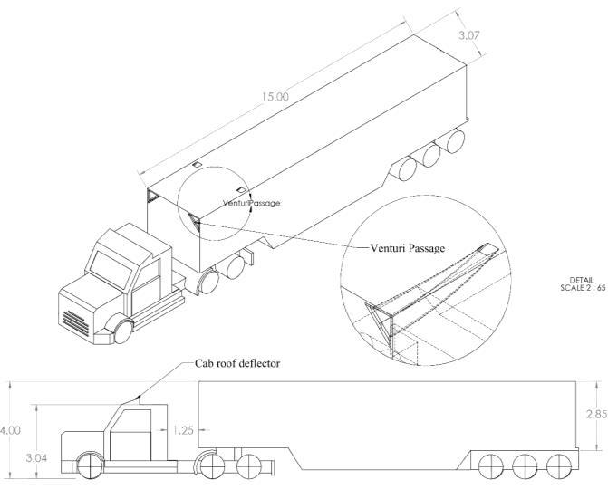
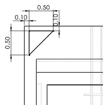
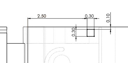
Additionally,triangularventuriventsaredesignedtomeet the lowest possible coefficient of drag, with 0.5m each of shorter sides which allows maximum intake of air at the trailerfrontarea.Figure1showshowgraduallytheareaof the venturi passage was reduced to maintain streamlined airflow with gradual pressure difference throughout the passage to create the lowest possible pressure difference withoutsideofair.Theexitofthepassagewasdesignedina squareshapeconfiguration,witheachsideoftwosides0.3m inlengthallowinglowturbulenceandsmoothexit.Asshown inFigure2,thelengthofthetotalarrangementfromentryto exitis2.5mwithaninsideedgeguidedcurvefilletof0.03m. For maximum drag reduction trailer air entry passage designed with 0.06m fillet over 0.05m of chamfer allows minimum flow separation and helps to create a smooth channelforstreamlineairflow.
TrailerTopview
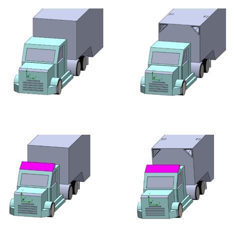
To identify the effectiveness of designed system over existing drag reducing devices for Articulated vehicles different configurations of trailer combinations have been investigatedwhichareasfollows:
Baseline testing: Conventional truck model (Fig 3) without any type of drag reducing devices and aerodynamicenhancements.
Venturi passage testing: Novel trailer design equipped with venturi passage (fig 4) to evaluate effectiveness throughdragreduction.
Cab roof deflector testing: Articulated model equipped with Cab roof deflector (fig 5) at various angles to observecoefficientofdragvalues.
CombinedVenturipassageandCabroofdeflectortesting: ThearticulatedmodelwasequippedwithbothVenturi passageandCabroofdeflectorenhancements(fig6)to verify drag reduction values, with different deflector angles.
International Research Journal of Engineering and Technology (IRJET) e-ISSN: 2395-0056
Volume: 11 Issue: 02 | Feb 2024 www.irjet.net p-ISSN: 2395-0072
CFD simulations were performed at full-scale models throughoutalltestsusingidenticalsimulationdomainsand configurations. Predefined SI(m-kg-S) unit systems were used; however, velocity parameters were defined in km/hour.Analysistype,flowattheexternalbodyonlywith consideringgravity,whichactsontheairstream.TheCFD analysis type was configured without rotation and free surfaceconditions.Projectfluidsaretakenasair(gases)with flow characteristics laminar and turbulent, considering no humidityconditions.Roughnessofwallwas0µmalongwith adiabatic wall parameters as a default thermal state. Additionally,thermodynamicsparametersincludepressure= +10^5Pa,temperature=20.05C˚,andvelocitydefinedin3D vectorwithvariablevelocityofairfordifferentscenariosin vehicledirectionwithturbulentintensityandlength0.1%, 0.031mrespectively
Moreover,thecomputationaldomaininthree-dimensional simulationwithsizeofX=33.1mand-13.45m,Y=8.3mand0.43m, Z = 5.5m and -2.39m including no boundary conditions. Usinga meshofthree-dimensional rectangular cells,SOLIDWORKSflowsimulationrepresentsfluidandsolid volumesusingtheFiniteVolume(FV)method.Thisadvanced computationalapproachensuresequaldistributionofmass, energy,andmomentumateachcell.Thecellslideron7in global automatic cell setting allows the study of air flow behaviouraccurately.Themeshcellcountduringtestswas 479k whereas the number of cells contacting solids was ~33k.TheseCFDtoolswereabletoprovideaccurateresults withdatabyprocessingitbysolversettings.
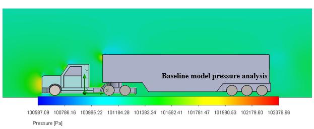
The findings of the CFD analysis represented base(conventional)testingasbluntbodywithacoefficientof dragof0.7245,withoutanyenhancementofthearticulated trailer. That value was supported by [11] which confirms, without any aerodynamic shaping the Cd value ranges between0.7to0.9.ThemodelwasdesignedinSolidWorks with 4m of trailer height from ground and 3.04m of cab height, calculated t/c ratio = 1.315. Air density is 1.225 kg/m3,andthevelocityofair,takenasaconstantflow,at30 m/s (108 km/hour) throughout the computation. As per Figure 7(a), an air separation bubble was visible in the velocity profile at the front of the vehicle and at the front trailer'sedgeareas,whereanincreaseinairpressurecauses anabruptdropinvelocity.TheCFDcalculateda highdrag valueduetothelargebasebakeregions,asthislow-pressure regiongeneratedduetoslowmomentumofairresultingin flowseparation.
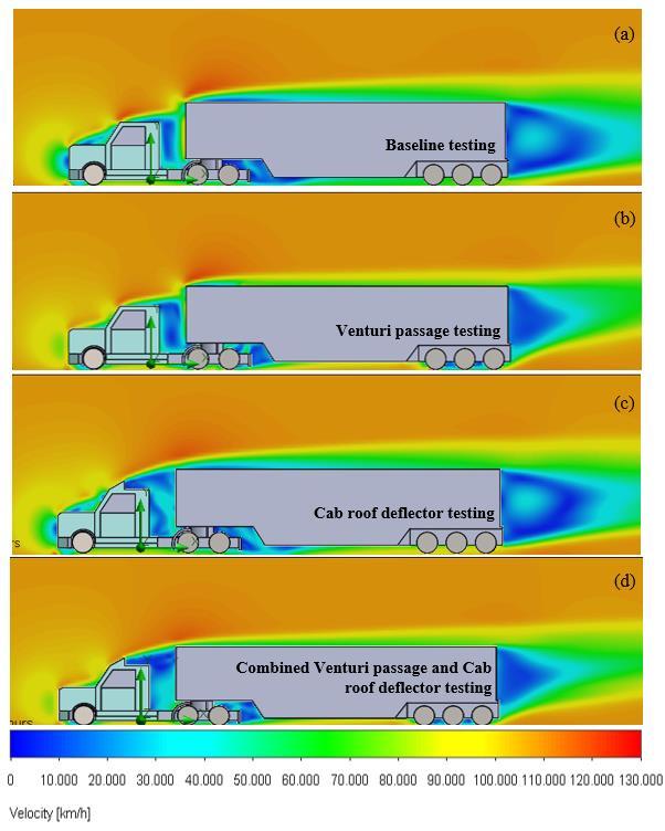
- 7(a-d):VelocityprofileofdifferentAerodynamic configurations
The Low-Pressure bubbles as per Figure 8 promote high velocitygeneration,wheretheflowremainsconnectedand streamlined over the articulated vehicle body which contributestoloweringthevalueofthecoefficientofdrag.
Volume: 11 Issue: 02 | Feb 2024 www.irjet.net p-ISSN: 2395-0072
The conventional body was subjected to a high drag coefficient due to sharp edges. However, venturi vents providepassagetopassairbytrailer.Theconstructiononly consumes0.5to0.7%volumeofcargo.Venturipassageasan aerodynamicenhancementdecreasedCdapproximatelyfrom 0.5 to 2% with no additional drag reduction attachments. Nonetheless,thedesignwassignificantlyeffectivewithhigh speeds, as arrangement provides more atmospheric air captureathighspeeds.Comparedtoaconventionaltrailer, thisnoveldesignwasabletoreducetheflowseparationon thetrailerleadingedgeconsideringsomeairpassesthrough aventuripassageandgraduallymergeswiththesurrounding air with the lowest possible level of pressure difference. Moreover,thepassageprovidesmorecontrolledflowover thesurface,minimizespressuredifference,andhelpstokeep downbasewakeasrepresentedinFigure7(b).
By utilizing Bernoulli’s principle as per equation 3, when pressureofairdecreases,velocityofairincreases.Figure9 makes this very noticeable, that high channel pressure at entry caused the air velocity to decrease, and the low pressureatexitcausedairvelocitytoincrease.Thepassage was optimized to minimize pressure difference with the outside atmosphere. Air velocity increases as it travels throughtheventuripassage,whichpreventsairrestriction withinthepassage.
Cabrooffairingsplayamajorroleinreducingairdragand fuelconsumption.Accordingtopreviousresearch[12],acab deflectorcontributestoreducingthedragcoefficientofheavy vehicles by 30% at 30 m/s vehicle driving speed. Cab deflectors are specifically made to improve the vehicle's overallaerodynamicsbydirectingairflowoverthebodyof
thevehicleandloweringtheamount ofairthatstrikesthe trailer directly. Comparison between venturi passage and deflectorconstructionrevealsthedifferenceofbasewakeas per Figure 7(b) and (c) respectively. Compared to the deflectortailermodelFigure7(c),theventuripassagemodel Figure7(b)exhibitsasmallerwakeregionconsideringthat thedeflectormodificationscausenotablywiderseparation layerwidthabovethetrailersurface.
Furthermore,avarietyofparameters,suchasthedeflector angle,thedistancebetweenthecabandtrailer,theshapeof thevehicle,thecabnose,andtheoperatingconditions,havea significant impact on the drag coefficient values. This is because different vehicle heights and dimensions result in differentoptimisationangles.
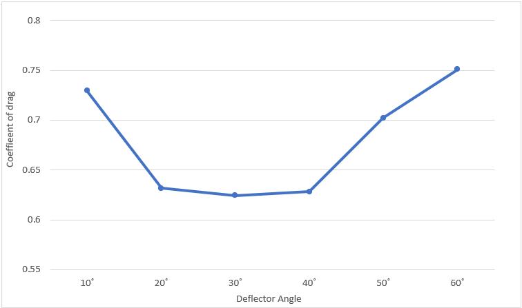
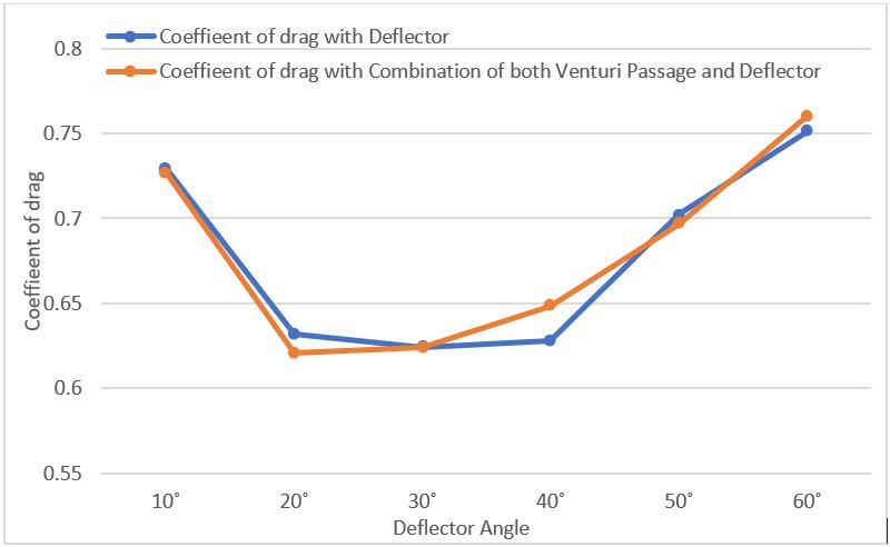
Thearticulatedtruckistestedataspeedof30m/sonvarious cabdeflectoranglesfrom10°to60°.Asaresult,theminimum angleof10°issubjectto0.729Cd,whiletheminimumdrag resistance of0.6244isvisible at a 30°deflectorangle,and after 40° drag starts to riseagain from 0.628 to 0.75. This highdragaftera40°anglewasbecausetheaircontactarea onthevehiclebodyincreases,causinganearlierseparationof theflowandthegenerationofturbulentflow,whichcreatesa highwakeregionattheendofthevehicle.
As an advanced technique, a combination of cab roof deflector and the venturi passage produces better results. Thisiscausedbytheventuripassage'sabilitytoletairpass throughandreduceairpressure,whichdirectlyactsonthe vehicletrailer.Additionally,thedeflectorhelpstoincrease overallperformancebyprovidingaguidedstreamlinedflow. Since the deflector's angle can greatly contribute to improvingtheangleofairattackovertheventurientrance. Therefore, it is most effective to position that at a specific anglerangefrom20°to40°,asChart1represents.
Moreover,deflectorshavealimitonhowmuchdragtheycan reduce at a given angle, vehicles that use an advanced combinationapproachwithventuripassagedesigns(VPDs)
International Research Journal of Engineering and Technology (IRJET) e-ISSN: 2395-0056
Volume: 11 Issue: 02 | Feb 2024 www.irjet.net p-ISSN: 2395-0072
offer greater flexibility and optimisation for a variety of articulatedvehiclesizesandshapes.
2:CombinedVenturipassageandCabroofdeflector analysis
Chart2showsthatacombinationapproachwithadeflector angle of 20° to 30° at a velocity of 30 m/s achieved the highestfueleconomybyminimizingdragvalue.Also,itwas clearthattheCdwillrisefurtherafter30°becausethehigh deflectorangleincreasesthevehicle'soveralldragforce(Fd) andcreatesnegativeairpressurebetweenthetrailerbody and the cab. As a result, a combination of both VPD and optimum deflector ranging from 20° to 30° CFD provided exceptionalvaluesof Cdandthatwillcontinuetodeclineas vehiclespeedincreases
Table – 1:DragcoefficientwithdifferentTractor-trailer configurationsat30m/s.
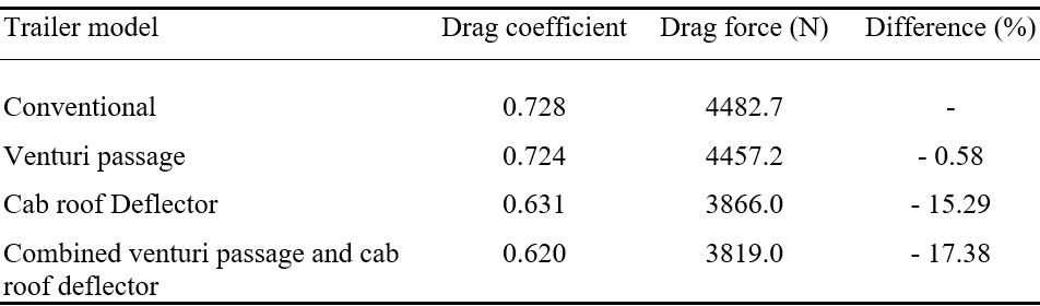
TheoptimisationofthecombinedVPDanddeflectormodel, asshowninTable1,revealsthattheadvancedcombination ofbothsystemsachievesthelowestcoefficientofdrag0.62. Comparedwiththeconventional(base)model,theonewith the20°deflectoranglecanhelpreducedragby17.38%.A vehicle with only a deflector installed facilitates drag reductionof15.29%,whichwas14%higherdragcompared tocombinationapproach.
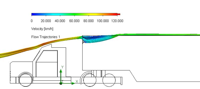
AccordingtothevehicleCFDanalysis,anaerodynamictrailer withoutanenclosedshape(figure10)thatmimicsventuri openaerodynamicstructuredesignoverthetraileredgeaids in directing airflow over the vehicle without further obstructingit.ThesimilarprofileofVPDoverthevehicleas an aerodynamic profile trailer edge provides less design complexity and simpler structural integration with the overalldesign.Nonetheless,anexaminationofthequantityof airstreamlineshowedthattheaeroprofileedgewasnotas effectiveasVPD,whichcouldpotentiallyincreaseturbulence andcreateahighnegativewakeregionatthevehicle'send. AccordingtoChart3,Aeroprofileleadstoahighdragvalue comparedtotheVPDapproach.
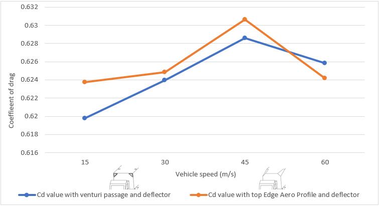
- 3:CombinedVenturipassageandAeroprofile combinationsanalysis.
The venturi passage with deflectorarrangement produced positiveoutcomeswithadragof0.619whenthevehiclewas travelling at 15 m/s. This is followed by 0.623 when the Aerofoil profile trailer edge is used. The negligible Cd differencecontinuestomaintainupto45m/svehiclespeed. According to equation 1 drag force is proportional to the square of velocity (Fd = 1/2 Cd ρAV2), where V is vehicle velocity.Thisindicatesthatasspeedincreases,theeffectof drag on the vehicle increases. The venturi passage design combinedwiththedeflectorwasmoreefficientinreducing flowseparationandturbulencecomparedtothetrailertop edgeAeroprofilesetupupto45m/sofspeed.
International Research Journal of Engineering and Technology (IRJET) e-ISSN: 2395-0056
Volume: 11 Issue: 02 | Feb 2024 www.irjet.net p-ISSN: 2395-0072
ThisCFDstudysuccessfullydemonstratedthefeasibilityof venturi passage design with the combination of cab roof deflector enhancements in an Articulated Lorry. The completecomparableexperimentwasinvestigatedat30m/s speed considering no crosswind condition and crosssectional area of the vehicle was 11.16m2. A complete computational study performed by actual scale model 1:1 demonstratedthattheuseofappendabledevicescanmake dragreductiononheavyvehicles.PressureandvelocityCFD profilediscoveredthattheadditionofventuripassagedesign on trailer edge is able to deliver high fuel efficiency by coefficientdragreductiononheavycommercialvehicles.
The test results displayed that earlier flow separation, pressuredifference,andbasewakeregionswerethemajor contributors to high drag values. In comparison with the conventional (baseline)trailer,0.58%dragreductionwas noted using a trailer that features a venturi passage. However,thecombinationofventuripassageandcabroof deflectorasnoveldragreducingapproachescompetentinup to 17.38 % of Cd reduction compared to the conventional approach.Cabroofdeflectorsolelyaccounts for15.29%of totalairdragreductioncomparedtobaseline.Despitethis, implementing a combination technique resulted in a 14% increase in performance, which allows transportation companiestoavoidspendingasignificantamountoffuel.
[1]D.Lowell,T.Balon,andM.J.Bradley,“SettingtheStagefor Regulation of Heavy-Duty Vehicle Fuel Economy & GHG Emissions: Issues and Opportunities Trucks and Climate Change.”[Online].Available:www.theicct.org
[2]C. Pevitt, H. Chowdury, H. Moriaand, and F. Alam, “A ComputationalSimulationofAerodynamicDragReductions forHeavyCommercialVehicles.”
[3]U. Department of Energy, “Research and Development OpportunitiesforHeavyTrucks,”2009.
[4]L. Salati, F. Cheli, and P. Schito, “Heavy Truck Drag ReductionObtainedfromDevicesInstalledontheTrailer,” SAEIntJCommerVeh,vol.8,no.2,pp.747–760,Sep.2015, doi:10.4271/2015-01-2898.
[5]M. J. lenngren Christoffer håkansson, “CFD Analysis of Aerodynamic Trailer Devices for Drag Reduction of Heavy Duty Trucks CHRISTOFFER HÅKANSSON,” Chalmers UniversityofTechnology,Göteborg,Sweden2010.Accessed: Feb. 25, 2024. [Online]. Available: https://publications.lib.chalmers.se/records/fulltext/13365 9.pdf
[6]M. Khosravi, F. osaddeghi, M. veisi, and A. hodayari-b, “Aerodynamicdragreductionofheavyvehiclesusingappend devicesbyCFDanalysis,”JCentSouthUniv,vol.22,no.12,pp. 4645–4652,Dec.2015,doi:10.1007/s11771-015-3015-7.
[7]D. Landman, R. Wood, W. Seay, and J. Bledsoe, “Understanding practical limits to heavy truck drag reduction,”SAEIntJCommerVeh,vol.2,no.2,pp.183–190, 2010,doi:10.4271/2009-01-2890.
[8]C. H. Marks, F. T. Buckley, and W. H. Walston, “An EvaluationoftheAerodynamicDragReductionsProducedby VariousCabRoofFairingsandaGapSealonTractor-Trailer Trucks,” 1976. [Online]. Available: https://www.jstor.org/stable/44644045
[9]K.RalinBukreev,“Shapeoptimisationofteardroptrailers to minimise aerodynamic drag in articulated lorries,” InternationalJournalofThermofluids,vol.18,May2023,doi: 10.1016/j.ijft.2023.100334.
[10] R.H.(RichardH.Barnard,Roadvehicleaerodynamic design :anintroduction.MechAero,2001.
[11] R.M.Wood,S.X.S.Bauer,andF.Worth,“2003-013377 Simple and Low-Cost Aerodynamic Drag Reduction DevicesforTractor-TrailerTrucksReprintedFrom:Vehicle Dynamics,Braking,SteeringandSuspensions(SP-1814)2003 SAEInternationalTruckandBusMeetingandExhibition.”
[12] J.J.Kim,J.Hong,andS.J.Lee,“Bio-inspiredcab-roof fairingofheavyvehiclesforenhancingdragreductionand drivingstability,”IntJMechSci,vol.131–132,pp.868–879, Oct.2017,doi:10.1016/j.ijmecsci.2017.08.010.