
International Research Journal of Engineering and Technology (IRJET) e-ISSN: 2395-0056
Volume: 11 Issue: 02 | Feb 2024 www.irjet.net p-ISSN: 2395-0072
International Research Journal of Engineering and Technology (IRJET) e-ISSN: 2395-0056
Volume: 11 Issue: 02 | Feb 2024 www.irjet.net p-ISSN: 2395-0072
Mohan Patwari1 , Ravindra Kachare2 , Sujeet Kumar3
1Sr. Design Engineer, Tata Technologies, ERC, Chassis, Tata Motors, Pune Maharashtra, India
2Team Lead, Tata Technologies, ERC, Chassis, Tata Motors, Pune Maharashtra, India
3Sr. Manager, ERC, Chassis, Tata Motors, Pune Maharashtra, India ***
Abstract – Camber angle is one of the main parameters of suspension system which affects, tire wear and handling of the vehicle. Camber angle is formed when vertical axis or top corner of tire is inclined outward or inward when seen from front or rear. Camber angle is said to be positive if top corner of the tire is outward and bottom corner of tire is inward. Camber is negative if top corner of tire is inward and bottom corner of tire is outward. Positive and negative camber set depending upon the suspension system geometry requirement. Static camber value varies if camber contributor parts are not in specified tolerance limit. To check maximum or minimum camber variation as per the tolerance given in part like control arm, chassis, wheel end etc., a tolerance stackup analysis is performed which helps to get maximum and minimum camber value. Vehicle behavior as per camber variation can be forecasted and it also shows the tolerance which to be controlled to minimize camber thrust, tire wear and poor ride handling [5]
Key Words: Tolerancestackupanalysisforcambervariation.
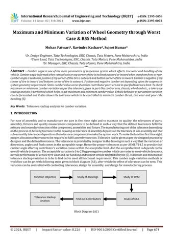
For ease of assembly and to manufacture the part in first time right and to maintain its quality, the tolerances of parts, assembly,fixturesandqualitymeasurementcomponentstobedefinedinsuchawaythatthedefinedtolerancesfulfilthe primaryandsecondaryfunctionofthecomponent,assembliesandfixture.Themanufacturingcostofthetolerancedependsup ontheprocessofdefiningtoleranceinthedrawingastoleranceofassemblydependsonthetoleranceofsub-assemblyandthat sub-assemblytolerancesdependsonthetolerancecomponentstomakethesystemwork.Tomakethefunctionfirsttimeright, properallocationoftolerancetoberequiredtofulfilassemblyfunction.Tolerancecanbegivenasperthedesignedpractiseby designerandthedefinedtolerances.Thetolerancesisprovidedbydesignerinthedrawinginsuchawaythatthevariationof dimension,anglesandflushcomesintheacceptablerange.HencethepropertolerancesasperASMEY14.5toprovidethat camberangleaffectingcontributor’svariationcomeswithintheacceptablelimit.Andtheacceptablelimitisdependsonthe overallvehicledynamics.Theacceptablevariationis0to2Degreenegativecamberwhichcanvariestomeetvehicledynamics, overallperformanceofvehicletyrewearandcarhandlingandtomeetvehicletargetedlifecycle[5].Maximumandminimumof tolerancestackupvariationistobetofindouttomeetallfunctionalrequirement.Thiscamberanglevariationmethodsor workflowcanbegetwithfollowingstepsgiveninblockdiagram(A1),afterwhichtheeffectoftolerancescanbeseen.This variationcanbecontrolledwithcontrollingtolerances,designforassembly,anddesignformanufacturingprocess.
International Research Journal of Engineering and Technology (IRJET) e-ISSN: 2395-0056
Volume: 11 Issue: 02 | Feb 2024 www.irjet.net p-ISSN: 2395-0072
Withfollowingtheprocessofblockdiagramtheoneexerciseisdonetounderstandthevariation.Itisbeenobservedthat majorfactorforcontributingcamberanglevariationarecontrolarm,damper,chassis,bodyinwideandwheelendassembly. WiththehelpofapplicationofworstcasemethodandRSSmethodandwithcreatingloopofdimensiontolerancemaximumand minimumvariationinthepartcanbefoundout.Contributortolerance,whichincludeslineartolerance,bilateraltoleranceorany other specified GD&T, modifier such as MMCand LMC are considered and followedthe loop in one direction. Sothe total toleranceofpartinmmthenconvertedtodegreewhichshowsthemaximumandminimumvariationincamberangle.
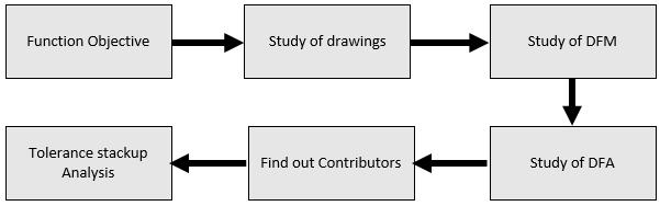
AlltheparametersvarythecamberangleasshownbelowwhichisanInclinationoftireinwardoroutwardfromverticalplane whenwheelviewedfromfront.
A. Camberangleis positive iftiretopcornerisinclinedtowardsoutsideofcar(seeimagebelow).
B. Camberangleis negative iftiretopcornerisinclinedtowardsinsideofcar(seeimagebelow).
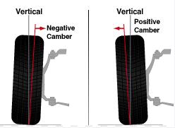
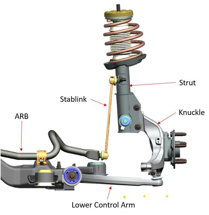
Referbelowexampletounderstandthecamberanglevariationandthenomenclatureofpartwhicharethemajorcontributing factorforcamberangle.
2
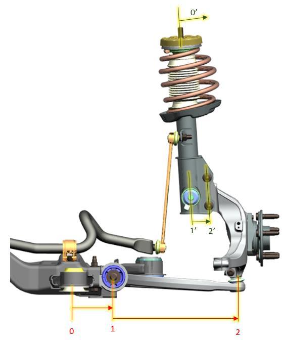
ThevariationcanbefoundoutwithcreatingloopsofdimensioninlateraldirectionasshowninFig.3.Thisloophasbeendivided intotwopartswhichareasbelow;
International Research Journal of Engineering and Technology (IRJET) e-ISSN: 2395-0056
Volume: 11 Issue: 02 | Feb 2024 www.irjet.net
Loop1(referFig.3)
0Subframe
0to1SubframetoLowercontrolarmmounting
1to2Lowercontrolarmmountingtoknuckleassembly
Loop2(referFig.3)
0’BIW
0’to1’BIWmountingtoStruttube
1’to2’Struttubetostrutmountingonknuckle
2395-0072
Theaimofdividingtheloopintotwopartsistofindthemaximumvariationbywhichthecamberanglecanbefinalizedandalso itcanbecontrolledwithmodifyingmajorcontributortolerance.Theloopsarecascadedintopartlevelandtheirdimensionsand tolerancesareconsideredasbelowtableAandtableB.
Table –A
Loop 1
0 Subframe
0to1 Subframeto Lowercontrol arm
1to2 Lowercontrol armto
1.Subframemountingholestolerances
2.BIWmountingholestolerances
3.Fastenerssizeandtolerances
1.Subframeholestolerancesforlowercontrolarm mounting
2.Lowercontrolarmholestolerances
3.Lowercontrolarmweldingtolerances
4.Lowercontrolarmfastenertolerances
5.Lowercontrolarmbushtolerances
1.Lowercontrolarmtolowerballjointparttolerances
2.Lowerballjointtolerances
3.Knuckleholetolerancesformountinglowerballjoint
International Research Journal of Engineering and Technology (IRJET) e-ISSN: 2395-0056
Volume: 11 Issue: 02 | Feb 2024 www.irjet.net p-ISSN: 2395-0072
Table –B
Loop 2
0’ BIW
0’to1’ BIWmountingto struttube
1’to2’ Struttubeto Knuckle mountingholes
1.BIWmountingholestolerances
2.Struttopmountingpinstolerances
3.Fastenerssizeandtolerances
1.Struttoptostruttubetolerances
1.Struttubetoknucklemountingholestolerances.
2.Knucklemountingholestolerances.
3.Knuckleholestolerances.
4.struttoknucklemountingfastenertolerances
Worst-casetoleranceanalysisisthetraditionaltypeoftolerancestackupcalculation.Theindividualvariablesareplacedat their tolerance limitsinorder tomake the measurementaslargeorassmall aspossible. The worst-casemodel does not considerthedistributionoftheindividualvariables,butratherthatthosevariablesdonotexceedtheirrespectivespecified limits. This model predicts the maximum expected variation of the measurement. Designing to worst-case tolerance requirementsguarantees100percentofthepartswillassembleandfunctionproperly,regardlessoftheactualcomponent variation.Themajordrawbackisthattheworst-casemodeloftenrequiresverytightindividualcomponenttolerances.The obviousresultisexpensivemanufacturingandinspectionprocessesand/orhighscraprates.Worst-casetoleranceisoften required by the customer for critical mechanical interfaces and spare part replacement interfaces [4]. When worst-case toleranceisnotacontractrequirement,properlyappliedstatisticaltolerancecanensureacceptableassemblyyieldswith increasedcomponenttolerancesandlowerfabricationcosts.
Therootsumsquared(RSS)methodisastatisticaltoleranceanalysismethod.Inmanycases,theactualindividualpart dimensionsoccurnearthecentreofthetolerancerangewithveryfewpartswithactualdimensionsnearthetolerancelimits [2].This,ofcourse,assumesthepartsaremostlycanteredandwithinthetolerancerange.RSSassumesthenormaldistribution describesthevariationofdimensions.Thebell-shapedcurveissymmetricalandfullydescribedwithtwoparameters,the mean,μ,andthestandarddeviation,σ.Thevariances,notthestandarddeviations,areadditiveandprovideanestimateofthe combinedpartvariation.
Variationincamberangleiscalculatedbytwomethods:
1. WorstcaseMethod
2. RSS(Rootsumsquaremethod)
Maximumandminimumtolerancearecalculatedwhichmayaffectthecamberangle.Wehaveaddedallparttoleranceand convertedittodegree.
Theresultofaddingthemeansandtakingtherootsumsquareofthestandarddeviationsprovidesanestimateofthenormal distributionofthetolerancestackandtheRSScanbecalculatedbybelowformula.
International Research Journal of Engineering and Technology (IRJET) e-ISSN: 2395-0056
Volume: 11 Issue: 02 | Feb 2024 www.irjet.net p-ISSN: 2395-0072
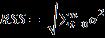
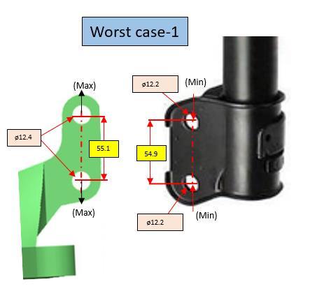
Themaincomponentwhichaffectcamberangledirectlyisknuckleandstrutmountingholes.Tooptimizethetolerancesbelow exerciseisalsobeendonewherethepartleveltolerancesareconsideredtofindoutfloattomountfasteners.
Thetolerancearetakenforknuckleandstrutholesoppositetoseetheworstcaseinbothpositiveandnegativeside(referworst case1)andviceVeraworstcase2.
NOTE: Abovedimensionstolerancesinresulttablearetakenforcasestudyandareforexampleonly.
ThecalculatedworstcaseandRSScasevaluefromLoop1andloop2aregivenasbelow.Thecrossadditionofmaximum variationfromloop1andminimumvariationfromloop2viceversagivesthetotalcamberanglevariationinwhichitcanbe convertedtodegreeanddegreetominutesasperformula(2).
Volume: 11 Issue: 02 | Feb 2024 www.irjet.net
Loop1
NOTE: Abovedimensionstolerancesinresulttablearetakenforcasestudyandareforexampleonly.
Above exampleoftolerance stackupanalysisisapplicablefor onedimensional analysisonly,whichishavingtheoptimal limitationsforthisparticularcasestudy.Inthiscasestudythegeometrydimensionsfeatures,primary,secondaryandtertiary datum’s,modifierssuchasLMC&MMC,RFS(ifapplicable),basicdimensionsinparts,alllinearandbilateraltolerancesare takenintoconsiderationtoperformthetolerancestackupanalysistofindoutmaximumandminimumcamberanglevariation. Andaspertheresultandmethodfollowedfromblockdiagram(A1),loopmethods,itcanbeseenthatthemajorcontributor's whichaffectthecamberanglesare;
1.Knuckle
2.Strut
3.BIW
4.Subframe
Thesecontributors’geometrydimensionandtolerancescanbemodifytogetthecamberanglewithintheacceptablerange whichisdefinedaspervehicledynamics,tyrewearandoverallperformanceofvehicle[4,5].
[1] ASMEY14.5(2018)Dimensioningandtolerancing.AmericanSocietyofMechanicalEngineers,NewYork
[2] RamiA.MusaandSamuelHuang,Y.KevinRong“Simulation-basedtolerancestackupanalysisinmachining”
[3] ChaseKW(1999)Toleranceallocationmethodsfordesigners.ADCATSRep99–6,BrighamYoungUniversity
[4] NumericalAnalysisoftheWheelCamberoftheFrontAxleofaPassengerCarDuringCorneringDenisMolnára*,Miroslav Blatnickýa,JánDižoa,VadymIshchuka
[5] SimulatedStudyontheEffectofCamberandToeontheHandlingCharacteristicsofaCarduringCorneringT.Vijayakumar andV.Ganesh
International Research Journal of Engineering and Technology (IRJET) e-ISSN: 2395-0056


Volume: 11 Issue: 02 | Feb 2024 www.irjet.net p-ISSN: 2395-0072 © 2024, IRJET | Impact Factor value: 8.226 | ISO 9001:2008
MohanPatwari,Sr.DesignEngg., Tata Technologies, ERC, Chassis, Tata Motors, Pune Maharashtra, India
RavindraKachare,TeamLead,Tata Technologies, ERC, Chassis, Tata Motors,PuneMaharashtra,India
Sujeet Kumar, Sr. Manager, ERC, Chassis, Tata Motors, Pune Maharashtra,India