
International Research Journal of Engineering and Technology (IRJET) e-ISSN: 2395-0056
Volume: 11 Issue: 02 | Feb 2024 www.irjet.net p-ISSN: 2395-0072
International Research Journal of Engineering and Technology (IRJET) e-ISSN: 2395-0056
Volume: 11 Issue: 02 | Feb 2024 www.irjet.net p-ISSN: 2395-0072
Siddhant Yadav1 , Rupesh Kumar Sahu2, Pratiksha Nirala3 , Mohini Moitra4
123UG Student, Department of Electrical & Electronics Engineering, CEC Bilaspur, Chhattisgarh, India
4Assistant Professor, Department of Electrical & Electronics Engineering, CEC Bilaspur, Chhattisgarh, India ***
Abstract - The main objective of the research project is to create a simulation model for three-phase symmetrical (Triple Line to Ground) and asymmetrical (Single Line Fault, Double Line Fault) analysis using MATLAB. These faults, which include single-line-to-ground, double-line-toground, triple-line-to-ground, and line-to-line faults, typically occur in long transmission line systems. Several fault types are analyzed and the results are shown in the simulation output, such as voltage and current. This study examines the MATLAB program used to simulate transmissionlinemodalities.
Key Words: Line to line fault, Line to ground fault, Double line to ground fault, symmetrical and asymmetrical faults,MATLABsoftware
1.
Fault analysis is helpful in determining the machine voltage and line current when colourful faults do in the system. The terms" line voltage" and" line current" are pivotal when dealing with an electrical system. There are substantiallytwotypesoffaultsintheelectricalsystem.A symmetrical fault is the first type and an asymmetrical fault is the alternate, similar as a single line- to- ground fault, a line- to- ground fault, a double line- to- ground fault, or a two- line fault (1). assaying power line faults is important from the point of view of electrical system protection. We use a three- line circuit swell and relay systemtocovertheelectricalsystem.
These are veritably common and less serious than symmetrical faults. These faults are generally known as three types videlicet single-phase earth fault also known asLGfault,twophaseshorttoeachotherandcurrentfault alsoknownaslinetoline(L-L),twophaseearthfaultalso knownasdoubleline.toground(L-L-G)blights.Line-toearth fault is the most common fault and 64- 69 of faults areofthistype.Thiscausesthelinetocommunicateearth orground.14-20percentoffaultsaredoublelinestobase and beget two cables to communicate ground. Line- toline faults do when two cables meet, substantially due to lineswingingcausedbywinds,and5-10percentoffaults areofthistype.
A symmetrical fault is one that affects every phase while keeping the system in balance. A symmetrical fault is one that occurs in three phases. These three fault types are appertained to as unsymmetrical or asymmetrical faults line to base, line to line, and two-line to ground. Symmetrical faults can be examined using per-phase analysissincetheyproducebalancedconditions.
ThereAreSeveralReasonofElectricalFault-
•ShortCircuitsEquipmentdamageandsystemdislocation canaffectfromthecreationofalow-resistanceroutethat allowsinordinatecurrentinflow.
• Voltage Unbalance Considerable variability in phase voltages may affect in outfit imbalance and possible malfunctions.
• Challenges with Grounding Wrong or shy grounding wayscouldcontributetocrimes.
• Environmental Factors Lightning strikes and other rainfall- related events can beget faults in outfit and lines ofelectricity.
Power outages, outfit damage, fires, and short circuits are just a many of the issues that can affect from electrical failures. They might be the consequence of effects like damagedsequestration,imperfectwiring,orbrokenoutfit. These troubles can be reduced with routine examinations andproperconservation.
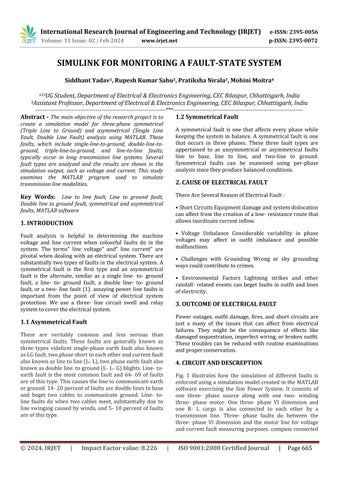
Fig. 1 illustrates how the simulation of different faults is enforcedusingasimulationmodelcreatedintheMATLAB software exercising the Sim Power System. It consists of one three- phase source along with one two- winding three- phase motor. One three- phase VI dimension and one R- L cargo is also connected to each other by a transmission line. Three- phase faults do between the three- phase VI dimension and the motor line for voltage andcurrentfault measuringpurposes.compassconnected
International Research Journal of Engineering and Technology (IRJET) e-ISSN: 2395-0056
Volume: 11 Issue: 02 | Feb 2024 www.irjet.net p-ISSN: 2395-0072
forvoltageandcurrentwaveformmeasuringpurpose.One Stepfunctionisalsousewho's
OneofMATLAB'smosthelpfulfunctionsforcontroldesign isthestepfunction.
5. SIMULATION RESULT
5.1 Under Non-Faulty Condition
All three phases have sinusoidal voltage and sinusoidal current while the system is in a Non faulty state, meaning that no faults are present in any of the lines. The voltage and current waveforms of a Non faulty system are displayedinnumbers2and3,independently.Everyoneof thethreestagesisinbalance.
5.2 Cause of Symmetrical Fault on voltage and current
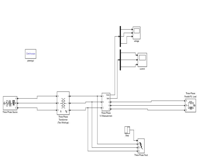
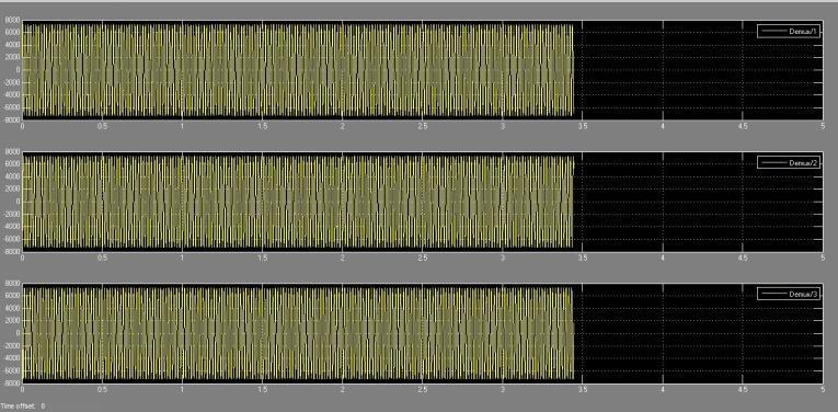
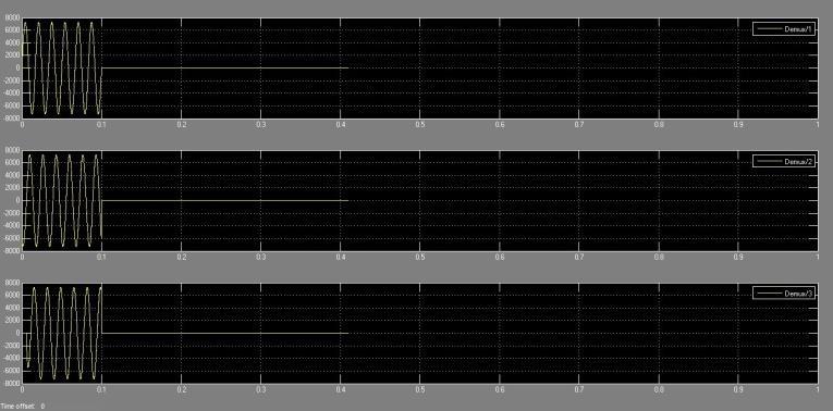
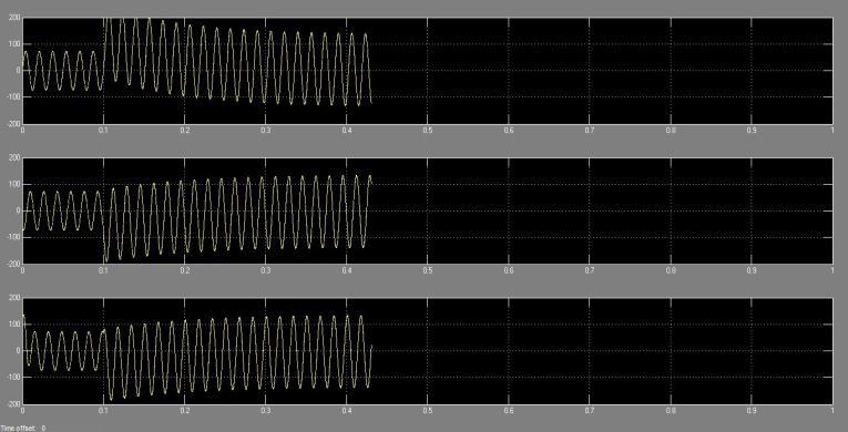
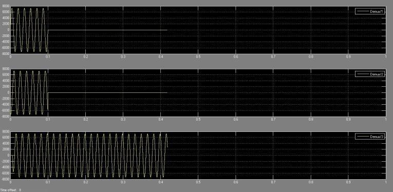
5.2.1 L-L-L-G Fault
Figures 5.2.1(a) and 5.2.1(b) display the voltage and current waveforms duringa triple-line fault inthesystem. At the fault occurrence at 0.1 seconds, all phase voltages swiftly plummet to zero, while the system's current experiencesasubstantialsurge,peakingat200A.
International Research Journal of Engineering and Technology (IRJET) e-ISSN: 2395-0056
Volume: 11 Issue: 02 | Feb 2024 www.irjet.net p-ISSN: 2395-0072
5.3 Cause of Asymmetrical Fault on voltage and current
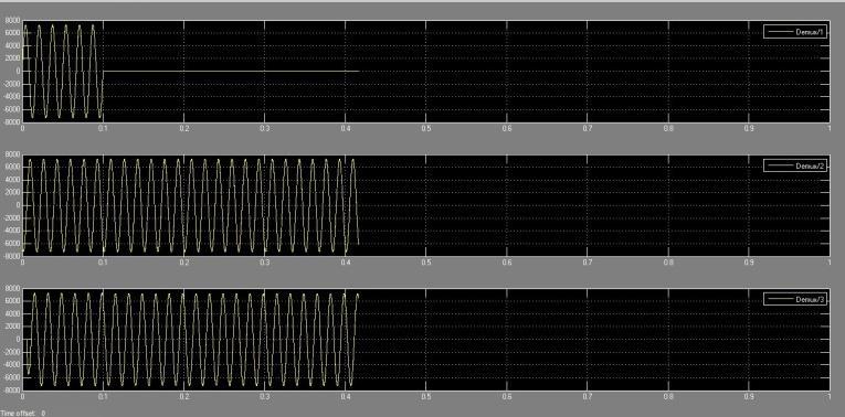
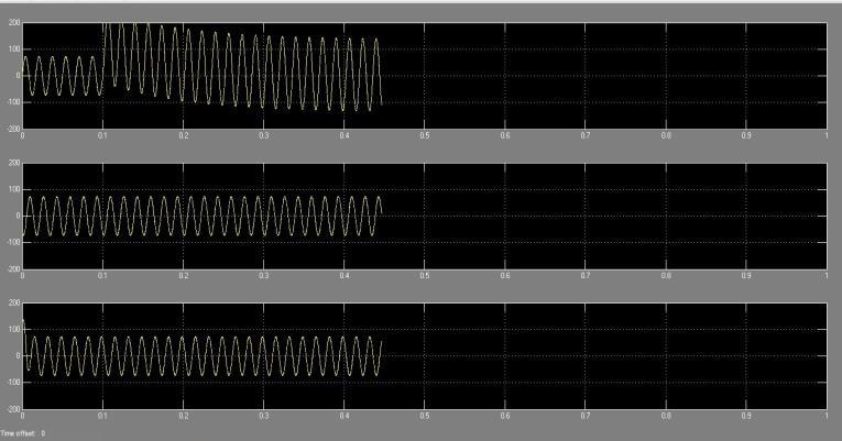
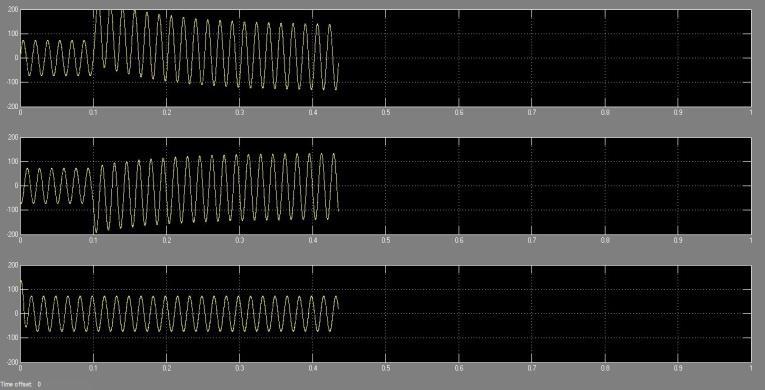
5.3.1 S-L-G Fault
In Figures 5.3.1(a) and 5.3.1(b), the voltage and current waveforms depict a single-line to ground fault in the system, specifically in phase A. At the fault instance at 0.1 seconds, the phase A voltage swiftly drops to zero, accompaniedbyasignificantsurgeinthecurrentoflineA, reachingapeakof200A.
5.3.2 L-L-G Fault
Figures 5.3.2(a) and Fig -5.3.2(b) illustrate voltage and currentwaveformsportrayingadouble-linetogroundfault in the system, affecting phases A and B. At the fault occurrence at 0.1 seconds, both phase A and B voltages rapidlydecreasetozero.Simultaneously,thereisanotable increaseinthecurrentoflinesAandB,peakingat200A.
6.
AsimulationstudyusingMATLABisconductedtoexamine thedifferentkindsofsymmetricalandasymmetricalfaults that can arise in the transmission line. Using the circuit swell,youcaninthehealthysystem,increaseanddropthe impactofafault.Ithasbeendissembledhowdifferentfault types, similar as single line to base, double line to base, threephase,andlinetoline,affectthevoltageandcurrent waveforms on the cargo side both during and after the fault. The theoretical aspects are vindicated by this simulationdisquisition.
[1] Dr. Shakuntla Boora, Mohit Yadav, Naveen Kumar, "MATLAB Simulation Based Study of Various Types of Faults Occurring in the Transmission Lines" International JournalofEngineeringResearch&Technology(IJERT),Vol. 8Issue12,December-2019
[2] S. Mahapatra and M. Singh, “Analysis of symmetrical fault in IEEE 14 bus system for enhancing over current protection scheme, “International Journal of Future Generation Communication and Networking, Volume 9, Issue4,pp.51-62,2016.
International Research Journal of Engineering and Technology (IRJET) e-ISSN: 2395-0056
Volume: 11 Issue: 02 | Feb 2024 www.irjet.net p-ISSN: 2395-0072
[3] S. Karekar and T. Barik, “A modelling of 440 KV EHV transmission line faults identified and analysis by using MATLAB,” IJAREEIE, Volume 5, Issue 3, pp. 1242-1249, , March2016.
[4] Analysis of Transmission Line Faults with Linear and Dynamic Loads Conference on Advances in Signal Processing (CASP)Cummins College of Engineering for Women.Pune,2016:p.2-5.
[5] C. Vijaya Tharani, M.N., R. Sundar and K. Nithiyananthan,<Paper38new.pd/>.2016.6
[6] Analysis of Transmission Line Faults with Linear and Dynamic Loads Conference on Advances in Signal Processing (CASP)Cummins College of Engineering for Women.Pune,2016:p.2-5.
[7] C. Vijaya Tharani, M. Nandini, R. Sundar and Dr. K. Nithiyananthan., “MATLAB based simulation model for three phase power system network,” Conference ProceedingsofICAET,pp.8-22,Chennai,2016.