
A Hybrid Routing Protocol to Support Mobility in LLNs
Alaa Althalji1, Souheil Khawatmi2, Bader Aldin Kassab3
1PhD Student, Systems & Computer Networks, Aleppo University, Syria.
2Associated Professor, Systems & Computer Networks, Aleppo University, Syria.
3Associated Professor, Systems & Computer Networks, Aleppo University, Syria.
Abstract - The development of devices and communication technologies has led to the concept of the InternetofThings(IoT),aimingtoconnecteverythingtothe Internet to facilitate communication and interaction between people and smart devices. However, smart devices often face limitations in power and memory. The IEEE 802.15.4 standard has low power consumption and bandwidth limitations, is well-suited for smart devices, and relies on the Routing Protocol for Low Power and Lossy Networks (RPL). Nonetheless, RPL lacks support for mobile nodes, posing challenges in achieving mobility without casuing overhead in low-power and lossy networks. This paper proposes HRP protocol which uses hybrid routing as an alternative to proactive routing in RPL. By using hybrid routing, updates in the routing table are reduced when nodes move, resulting in fewer control packets, so reduced overhead. A performance evaluation of HRP shows it is superior to the proposed protocols in previous studies. The proposed approach improved efficiency by minimizing updates and overhead, thus addressing the challenge of supporting mobile nodes in low-power and lossy networks. This research contributes to supporting mobile nodes withoutaffectingthenetworkperformance.
Key Words: Proactive, Reactive, Hybrid, IoT, LLN, RPL.
1.INTRODUCTION
The Internet of Things (IoT) enables ubiquitous connectivityforsmartdevices,allowingthemtoconnectto the Internet at any time and location [1]. Smart devices, characterized by low power and limited processing and memory capabilities, form a self-organizing network without the need for infrastructure, with nodes acting as routers. Smart devices utilize the IEEE 802.15.4 standard [2] and the Routing Protocol for Low Power and Lossy Networks (RPL) [3]. However, RPL lacks support for mobile nodes, leading to increased overhead due to the transmissionofadditionalcontrolpacketsinthenetwork.
So much research improved RPL to support moil nodes. Our paper proposesa lightweight hybrid routing protocol. Unlike reactive routing, thehybrid protocol minimizes the number of control packets and reduces the frequency of routing table updates compared to proactive routing. This approachiswell-suitedfordeviceswithlimitedresources.
1.1 Routing Protocol for Low Power and Lossy Networks [3]:
The RPL routing protocol, developed by the Routing Over Low-Power and Lossy Networks (ROLL) group, is specifiedinRFC6550.InRPL,arootnodeactsasagateway to the Internet, enablingcommunication among devices in the network. The topology is organized as a Directed Acyclic Graph (DAG) with the root node. The root node periodically sends DODAG Information Object (DIO) messages to invite neighboring nodes to connect with the root node. Each node that receives the DIO message and desires communication with the root node responds by sending a Destination Advertisement Object (DAO) message. This process continues until all nodes in the networkareconnected,asillustratedinFigure1.
To manage the timers for DIO messages and minimize overhead in the networks, so RPL uses the Trickle algorithm. The Trickle algorithm adjusts the transmission rateofcontrolmessagesbasedonnetworkstability.When an unstable state is detected, the transmission rate increases to spread the updates. Conversely, when the network stabilizes, the transmission rate decreases,reducingunnecessaryoverhead[4].

TheparentnodeisselectedusingObjectiveFunction(OF0) that depends on hop count. OF is developed to MRHOF (The Minimum Rank with Hysteresis Objective Function) [5],whichtheparentnodeisselectedbasedonthevalueof the Expected Transmission Count (ETX) that determines thequalityofthelink.
1.2 Routing types
There are three types of routing protocols: proactive, reactive, and hybrid. Proactive protocols maintain up-todate routing information in tables and scatter update
International Research Journal of Engineering and Technology (IRJET) e-ISSN: 2395-0056 Volume: 11 Issue: 01 | Jan 2024 www.irjet.net p-ISSN: 2395-0072 © 2024, IRJET | Impact Factor value: 8.226 | ISO 9001:2008 Certified Journal | Page498
***
Fig -1:ExampleofusingRPLinnetwork
messages across the network. Reactive protocols generate routes when necessary, using a path discovery method in which control messages are flooded across the network. Hybrid protocols combine proactive and reactive routing, which split the topology into zones and use a proactive protocol intra-zone routingsincethese protocols maintain an up-to-date view of the topology of the zone, which resultsinnoinitialdelaywhencommunicatingwithnodes within the zone, and a reactive protocol performs interzonerouting.[6]
RPL is a proactive routing protocol primarily designed for static devices rather than mobile ones. Proactive routing with mobile nodes induces overhead and power consumption, making it unsuitable for battery-powered devices to update the routing table during node mobility. Ontheotherhand,usingareactiveroutingprotocolisalso not the right choice because it depends on making nodes send periodic control messages, whichincreases overhead and power consumption. So this paper depends on hybrid routing.
2. Related work
P2P-RPL protocol (RFC 6997) [7] uses a route discoverymechanismwhereaP2PRouteDiscoveryObject (P2P-RDO)messageisbroadcasted,andthenintermediate ortargetnodesrespondwithaP2PDiscoveryReplyObject (P2P-DRO) message. However, a drawback of P2P-RPL is thenetwork floodingofcontrol messagesduringtheroute discoveryphase,leadingtoincreasedconsumption.
Fotouhi proposed the MRPL protocol [8], which integrates RPL with smart hopping using beacons. The MRPLprotocolconsistsoftwophases:routediscoveryand data transmission. During the route discovery phase, a mobile node broadcasts multiple DIS messages. The receiving nodes calculate the Average Received Signal Strength Indicator (ARSSI) and include this value in a DIO message.Themobilenodeselectsitsparentnodebasedon theDIOmessagewiththehighestARSSI
Gara [9] suggests an adaptive timer algorithm to regulatethetransmissionofDIOandDISmessagessentby mobile nodes. This algorithm computes the remaining distance(d)foranodetoleavetheradiorangeofitsparent nodebysubtractingtheparentnode'sradiorangefromthe distance between the two nodes. As (d) becomes shorter, the node discovers to find a new parent node. The proposed algorithm utilizes ETX and RSSI values to determinethebestparentnode.
In [10], the EMAEER protocol is proposed, which dividesthenetworkintonon-overlappingregionsbasedon the Euclidean distance to the reference node (containing GPS).Eachtimeanodewantstotransmitdata,itconstructs a network tree with itself as the root. However, this approach increased power consumption and overhead since all nodes participate in the route discovery phase. EMAEER supports mobile nodes but experiences
performance degradation as the number of mobile nodes increases
Sanshi[11]modifiedtheRPLprotocolusingfuzzylogic with parameters (residual power, expected transfer count (ETX), RSSI, and mobility timer). FL-RPL incorporates the mobilitytimerparameter,whichestimatesthetimeanode will remain within radio range based on location information obtained from RSSI. However, this method is not accurate due to obstacles and interference. Mobile nodes are treated as leaf nodes and cannot participate in the routing process, which is not suitable when the networkhasmoremobilenodesthanstaticones
Safaei [12] proposed the ARMOR protocol, introducing anewparametercalledTime-to-Reside(TTR)toselectthe best parent node that will remain within radio range for thelongesttime.TTRiscalculatedbasedonanode'sspeed and position and is included in the DIO message. The researchalsoproposedanewtimertoincreasetherateof sending DIO messages by static nodes, enabling them to introduce themselves and be selected as parent nodes by mobilenodes.Themobilenodesdidnotmodifytheirtimer, butthisisnotsuitableforitsneighbornodestobeawareof theircurrentspeedincaseitchanges.
MobiRPL [13] utilizes RSSI and hop count to classify nodes into three categories. Nodes with RSSI above a specificthresholdareconsideredwhiteareanodesandare preferred over others. Nodes with lower RSSI are categorized as gray area nodes. Black area nodes are not connected to the network and are not selected as parent nodesuntiltheyreconnecttothenetwork
V-RPL [14] is a proactive routing protocol that uses multiple criteria for parent node selection, including RSSI, noderank,linkquality,andremainingenergy.Additionally, it modifies the timer algorithm based on the speed of neighboring nodes. When the speed of neighboring nodes increases, the timer period decreases. The node calculates its speed by measuring the interval time between two successiveDIOpacketsandincludesthisinformationinthe DIO message sent to neighboring nodes. As a result of the research, the packet delivery ratio reached less than 70% whenhalfofthenodesweremobileinthenetwork.
The research [15] introduced a new objective function called rpl-TotEg-Neighbors, which takes into account the node's energy, the number of neighbor nodes, and the expected transmission count (ETX). When selecting the parent node, the energy value is given the highest weight, followed by the number of neighboring nodes and ETX. Comparative evaluations were conducted with the objective function (of0, MRHOF) using various movement patterns. The results showed the superiority of the proposed objective function, but it increased energy consumption.
The related work led to increased delay and overhead in the network. So was the need for a protocol that supports
International Research Journal of Engineering and Technology (IRJET) e-ISSN: 2395-0056 Volume: 11 Issue: 01 | Jan 2024 www.irjet.net p-ISSN: 2395-0072 © 2024, IRJET | Impact Factor value: 8.226 | ISO 9001:2008 Certified Journal | Page499
mobility. This research proposed using hybrid routing, which aims to strike a balance between mobility support andnetworkefficiency.
3. Hybrid Routing Protocol (HRP)
HRP divides the network into regions by informing the network about subtrees. Within each subtree, proactive routing is utilized, allowing nodes to establish and maintain routes. On the other hand, between different subtrees, reactive routing is employed. When a route is required between subtrees, nodes initiate a reactive routingprocesstoestablishthenecessarypath.Thismixed approach aims to achieve efficient routing while consideringthemobilityofnodeswithinthenetwork.
3.1 Proposed control message
The HRP control messages consist of an ICMPV6 [16] header followed by a message body. To support hybrid routing mechanism in HRP protocol, various control messages are proposed for network construction and maintenance.Theyare:
Neighbor Information Solicitation (NIS)
TheNISmessageisusedtosolicitatreeofInformation fromanothernodeinordertoestablishaconnectionwith it.ThestructureoftheNISframeconsistsof4bytes unused,soMUSTbeinitializedtozerobythesenderand MUSTbeignoredbythereceiver.ThestructureofNISis showninFigure(2)
Neighbor Information Object (NIO):
Thenodesendstheproposedcontrolmessage(NIO)to informitselfwiththefollowinginformation:
- Height_sub_tree: A byte that stores the distance betweenthenodeandthesubrootofthesubtreetowhich itbelongs.
- Hop_count:abytethatstoresthenumberofhops betweenanodeandtherootofthemaintree.
- Mobility_Level: a byte that stores a value that determines the mobility level of the node, whether it is staticormoving.
- Flags: A byte where only two bits are utilized, whilethe remaining bitsmust be initialized to zeroby the
senderandignoredbythereceiver.Thetwobitswithinthe Flagsfieldareasfollows:
Energy Type flag: This flag should be set to 1 if the nodeisconnectedtoanelectricalpowersource.Otherwise, itisassignedavalueof0,indicatingthatthenoderelieson batterypower.
WarningBatteryflag:Thisflagshouldbesetto1when the node's power level reaches a critically low state and requiresrecharging.
The structure of NIO is shown in Figure (3). The node that receives the NIO control message has to decide if wants to connect with it as a parent node, depending on context-aware method [17] using the parameters value thatgetsthemfromtheNIOpacket.

Neighbor Advertisement Object (NAO)
The node that receives the NIO control message and decides to connect with it as the parent node sends the corresponding control message called NAO. The structure oftheNAOframeconsistsofthefollowingfields:
- Flags:abyteofwhichonlyonebitisusedforthe sub_rootflagthatindicateswhetherthenodeisasub-root, andtherestofthebitsmustbeassignedavalueofzero.
- Unassigned bits of the NAO Base are reserved. They MUST be set to zero on transmission and MUST be ignoredonreception
- Options: This specification does not define any options.SotheyaresettozeroontransmissionandMUST beignoredonreception
ThestructureofNAOisshowninFigure(4)

International Research Journal of Engineering and Technology (IRJET) e-ISSN: 2395-0056 Volume: 11 Issue: 01 | Jan 2024 www.irjet.net p-ISSN: 2395-0072 © 2024, IRJET | Impact Factor value: 8.226 | ISO 9001:2008 Certified Journal | Page500
Fig -2:ThestructureofNIS
Fig -3:ThestructureofNIO
Fig -4:ThestructureofNAO
3.2 Building the network:
The network is comprised of multiple sub-trees, each having a sub-root. Proactive routing is employed within eachsub-tree,whilereactiveroutingisutilizedtoestablish communicationbetweendifferentsub-trees.
The network formation begins with the root node sending a control message called Neighbor Information Object (NIO). This message carries essential information thatenablesanodetodiscoverthenetworkandacquireits configuration parameters. Neighboring nodes respond to the NIO message by sending a proposed control message known as Neighbor Advertisement Object (NAO) if it is suitabletoconnectwithitasaparentnods.Eachconnected node in the network will propagate the NIO message to informitselfandupdateitsknowledgeaboutthenetwork.
Once a child node selects a parent node based on the information received in the NIO message, it calculates its heightwithinthesubtreetowhichitbelongs.
IfthenetworkisinitsinitialstageandtheHeight_sub_tree value is 3 hops, the node is considered a sub-root if it is static. If the next node is static, it will be a sub-root. However, if the node is mobile, so when a new node connectstoanetworkthathasaHeight_sub_treeof5hops, it is considered a sub-root regardless of its mobility level. Subsequently, the node sends an NAO message to its chosen parent node to confirm communication and indicatewhetheritisactingasasub-root
3.3 Routing table
The sub-root node plays a crucial role in the hybrid networkbystoringroutinginformationforallnodeswithin itssubtree,aswellastherouteinformationfordownward sub-root nodes. Each node within the network maintains the necessary downward routes within its respective subtree.Whenanodeorsub-rootnodereceivesaNeighbor Advertisement Object (NAO) message from another subrootnode,itstorestherouteinformationforthatnodeand forwardsthemessagetoitsparentnode.
In a hybrid network, the advantage lies in the reduced number of routing table updates required when mobile nodesmove,incomparisontoproactiverouting.Insteadof updating routing information for every node in the network, the updates are localized to the sub-root nodes. Consequently, the need for extensive updates throughout theentirenetworkisminimized.
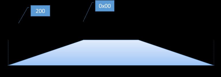
Figure 5 illustrates an example network utilizing the Hybrid Routing Protocol (HRP) for network construction, where the orange nodes represent sub-root nodes, and each rectangle represents a tree. This network structure allowsforefficientroutingandfillingofroutingtables.
4. Repair the network:
We have proposed rules to maintain the network when a node experiences a problem or moves out of its parent node'srange.Herearetherules:
-Ifasub-rootnodeexperiencesanissue,itschildnodewill searchforanewparentnode.
-Ifanodejoinsasubtree,itwillcalculateitsdistancefrom theroot.Ifitsheightexceeds6,itidentifiesitselfasa subrootnode.
- If the tree height decreases, then there is no change. However, if the tree height becomes less than 2, then we cancelthesub_rootattributeofthenode.
-Ifthetreeheightincreases,thenthenodethatcalculates its distance from thesub-root of the tree will be given the rootattributeifthevaluebecomesmorethan6.
5. Evaluating the performance of the HRP protocol
To evaluate the performance of the Hybrid Routing Protocol (HRP), we utilized Contiki's IoT simulator called Cooja [18], which supports various IoT platforms such as ZolertiaOne(Z1),Skymote,andWismote.
In order to evaluate the performance of HRP, we compareitwithmanypaper:
1) MobiRPL: Adaptive, robust, and RSSI-based mobileroutinginlowpowerandlossynetworks [13]
The research relied on several scenarios cooja1, cooja2,andcooja3.Thecomparisonwiththestandard RPLprotocolshoweditssuperiorityoverit
International Research Journal of Engineering and Technology (IRJET) e-ISSN: 2395-0056 Volume: 11 Issue: 01 | Jan 2024 www.irjet.net p-ISSN: 2395-0072 © 2024, IRJET | Impact Factor value: 8.226 | ISO 9001:2008 Certified Journal | Page501
Fig -5:ExampleofnetworkusingHRP

Figure (6) shows the Cooja1
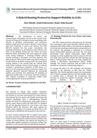
with 12 static nodes, a mobile node, and a root. All the nodes have the same transmission range (50 m), and one exampleisindicatedbyalargelightbluecircle.
Thenetworkcontains:
- 12static nodes(nodeswithID2to13). Thedistancebetweenthemis40meters.
- onemobilenode,whichisthenodewithID 14thatmovesataspeedof1m/s.
- OnerootisthenodewithID1.
Onedatapacketissentevery30seconds.MobiRPL evaluatedtheperformancewithdifferentspeeds.The resultswereasfollows:
Packetdeliveryratioofmobilenode:
Chart(1),Wenotethattheresultisclosebetween MobiRPLandHRPbecausethenetworkcontainsonly one mobile node at low speeds, so the difference between the performance of the two protocols will notappearclearly.
PDR decreased when speed increased. When the nodespeedincreasesto(5m/s),HRPrecordsahigher PDR than MobiRPL because it helps to organize the networkbysubtrees,reducingcollisions.
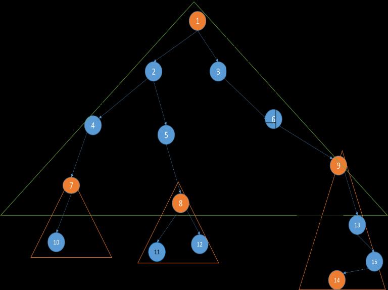
Figure (7) shows the Cooja2 scenario, with one rootnodeandsixstaticnodes,wherethesmallcircles indicatethecoveragearea ofthe static nodesandthe number of different mobile nodes up to 18 nodes moving at a speed of m/s (0.5 - 2.0) within the area covered by the large circle. One data packet is sent every 60 seconds. The performance was evaluated withdifferentnumbersofmobilenodes.
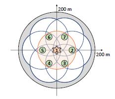
Fig -7:Simulation(Cooja-2)
Packetdeliveryrateformobilenodes:
The PDR to mobile nodes using the MobiRPL protocol Chart (2) ranges from 80 to 85 when the number of nodes increases. Using the proposed HRP protocol, the PDR ranges between 85 and 90. The positive impact of mobile nodes is that they participateinpacketforwarding.
Chart -2:PDRversusnumberofmobilenodes
The average duty cycle of mobile nodes is high in the MobiRPL protocol Chart (3) due to the mobile nodes’ routing and forwarding overheads. MobiRPL relies on a mechanism to verify communication between nodes by sending n DIS messages to be responded to with DIO messages.Thus,nodesarestillonmostofthetimetosend control messages, which affects the duty cycle of static nodes, as shown in Chart (4). But HRP is less resourceintensive as it employs hybrid routing, which means that therearefewerupdatesoftheroutingtableifmobilenodes move. which lower the number of control packets, so less dutycycle.
International Research Journal of Engineering and Technology (IRJET) e-ISSN: 2395-0056 Volume: 11 Issue: 01 | Jan 2024 www.irjet.net p-ISSN: 2395-0072 © 2024, IRJET | Impact Factor value: 8.226 | ISO 9001:2008 Certified Journal | Page502
Fig -6:Cooja1scenario
scenario
Chart -1:PDRversusthespeedofthemobile
75 80 85 90 95 2 3 6 12 18 PDR % Number of mobile nodes
MobiRPL HRP 0 20 40 60 80 100 120 0.5 1 2 5 PDR% speed (m/s) MobiRPL HRP RPL
PDR (mobile node)
Figure (8) shows the Cooja3
a
250
The analysis of different simulation topologies aims to assess the effect of network size on the performance and connectivity of the MobiRPL protocol.TheMobiRPLprotocolisanalyzedusingtwo different simulation topologies: Cooja-2 with a radius of 200 meters and Cooja-3 with a radius of 250 meters.ThewiderareacoveredbyCooja-3mayresult insomenodesbeingunabletoestablishaconnection with the root node when a node is located at a point empty of another node because the area is wide and therelativelysmallnumberofnodesavailable.

Packet delivery rate: with a wider network area, the PDR decreases, so less transmission, which reduces the duty cycle because it is calculated from radio listen and radio transmit, which is shown in Chart(5),Chart(6),andtheChart(7).
Chart -5:PDRinCooja-2vsCooja-3(mobilenode)
Chart -6:DutycycleinCooja-2vsCooja-3(mobilenode)
Chart -7:DutycycleinCooja-2vsCooja-3(staticnode)
2) V-RPL: An effective routing algorithm for low power and lossy networks using multi-criteria decision-makingtechniques(2022)[14]
This research implements scenario A (half of the nodes are mobile) and scenario B (all nodes are
International Research Journal of Engineering and Technology (IRJET) e-ISSN: 2395-0056 Volume: 11 Issue: 01 | Jan 2024 www.irjet.net p-ISSN: 2395-0072 © 2024, IRJET | Impact Factor value: 8.226 | ISO 9001:2008 Certified Journal | Page503
Chart -3:Dutycycleversusnumberofmobilenodes
Chart -4:Dutycycleversusnumberofstaticnodes
scenario. The simulation topology has
radius of
meters with 18mobilenodes.
Fig -8:Simulation(Cooja-3)
0 2 4 6 8 2 3 6 12 18 Du ty cy cle (% ) Number of mobile nodes Duty cycle (mobile node) MobiRPL HRP 0 2 4 6 8 2 3 6 12 18 Du ty cy cle (% ) Number of mobile nodes Duty cycle (static node) MobiRPL HRP 0 20 40 60 80 100 Cooja-3
PDR % PDR (mobile
MobiRPL HRP 0 2 4 6 8 Cooja-3 Cooja-2 Du ty cy cle % Duty cycle (static node) 0 5 10 cooja-3 cooja-2 Du ty cy cle % Duty cycle
MobiRPL
Cooja-2
node)
(mobile node)
HRP
mobile).TheSimulationtimeis3000seconds.Witha network area of300*300m.Whereas inScenarioA, thenodespeedis(1-2)m/s.Theeffectofnodespeed wasanalyzedinthepresenceof20mobilenodes,and anotherscenariohas40nodesthatarehalfmobile.


To study the effect of increasing the number of mobile nodes in the network on performance, we compare Chart(8) (the caseof 20 mobile nodes) and Chart (9) (the case of 40 mobile nodes). We notice thatthepacketdeliveryratiodecreasesasthenumber of mobile nodes in the network increases due to collisions. The network is more stable if there are static nodes,sothereisnoneedtochangetheparent nodeeverytimethenodemoves.
The packet delivery ratio of the proposed HRP protocol wasclose tothe V-RPLprotocol because the V-RPLprotocolreliedondecreasingtheintervalvalue of DIO control messages, which helps maintain network stability and reduce disconnection between nodes,butthisincreasestheoverhead.
We also note that it increased delay and power consumption.Chart(10),whichshowsthevalueofthe delay with the simulation time, whereas the time increases, the delay increases, and the HRP proposed protocol helped reduce the delay. Chart (11) shows that the proposed protocol consumed less energy evenifallnodesweremobile
Chart -10:PDRversussimulationtime(N =20).
Chart -11:Averageenergyconsumptionvsthe rateofmobilenode
3) ARMOR: A Reliable and Mobility-aware RPL for Mobile Internet of Things Infrastructures (2021)[12]
The area simulation is 10,000 m2, the number of nodes (20,40), half of which are mobile nodes with speeds of 0.5-1.5 m/s according to mobility models (Manhattan, Random Movement Model). The simulation

Manhattan mobility model: It is a model of movementwithinthecity.Thenodesmoveaccording tohorizontalandverticalstreetsaccordingtothemap ofthearea,Figure(9).[19]
International Research Journal of Engineering and Technology (IRJET) e-ISSN: 2395-0056 Volume: 11 Issue: 01 | Jan 2024 www.irjet.net p-ISSN: 2395-0072 © 2024, IRJET | Impact Factor value: 8.226 | ISO 9001:2008 Certified Journal | Page504
Chart -8:PDRversusaveragevelocityofmobile nodes(N =20).
Chart -9:PDRversusaveragevelocityofmobile nodes(N =40).
1 10 100 1000 500 1000 1500 2000 2500 3000 Av e rage e n dtoe n d d e lay (m s ) Time(s)V-RPL HRP 0 50 100 semi-mobile mobile nodes Av e ra ge e n e rgy con s u m p tio n (mJ ) Average energy consumption of a mobile node V-RPL HRP time is3600s.
Fig -9:Manhattanmobilitymode
HRP's proposed protocol outperformed the ARMOR protocol in both mobility models due to its ability to increase the stability of the network and selectthemostsuitableparentnode.ARMORreliedon RSSI value to calculate the speed of the nodes and select the parent node, but RSSI value is affected by obstacles,soitisnotalwayscorrect.
HRP gives a greater packet delivery rate with the random waypoint model(RWP), so HRP is more suitable for RWP than the Manhattan model. We also notice by comparing Chart (12) and Chart (13) that whenincreasingthenumberofnodesinthenetwork, the packet delivery ratio increases because the network area is wide, so increasing the number of nodeswillhelpthemtoconnectwiththenetwork.
Theincreaseinthepacketdeliveryratiomeansthe network is stable, so less power consumption, as shown in Chart (14), and less overhead on the network,asinChart(15)


Power consumption increases with the number of nodes due to the increase in sending control messages to build and repair the network and to choose the most appropriate parent node. Chart (16) shows that control packets cause an increase in overhead, so our goal with HRP's proposed protocol was not to increase the rate of
sending control packets. However, the ARMOR protocol relied on modifying the timer to increase sending control packets,sooverheadincreasedsignificantly.Bycomparing Chart(16)andChart(17) increasingthe number ofnodes in the network will increase the rate of sending control packets.

International Research Journal of Engineering and Technology (IRJET) e-ISSN: 2395-0056 Volume: 11 Issue: 01 | Jan 2024 www.irjet.net p-ISSN: 2395-0072 © 2024, IRJET | Impact Factor value: 8.226 | ISO 9001:2008 Certified Journal | Page505
Chart -12:Packetdeliveryratevsmobilitymodel (n=20)
Chart -13:Packetdeliveryratevsmobilitymodel (n=40)
Chart -14:Powerconsumptionvsmobilitymodel (n=20)
0 20 40 60 80 100 Random way point manhattan Po w e r Con s u m p tio n (mW) Mobility model 40 node scenario: mobile nodes 0 20 40 60 80 100 Random way point manhattan Po w er Co n s u m p t i o n ( m W ) Mobility model
Chart -15:Powerconsumptionvsmobilitymodel (n=40)
Chart -16:controlpacketsoverheadvsmobility model(n=20)
4) ANewObjectiveFunctionforRPLBasedon Combined Metrics in Mobile IoT (2023) [15]
In this research, a new objective function rplTotEg-Neighbors was proposed that depends on the energy of the nodes, the number of neighboring nodes, and the value of the expected transmission count(ETX).Thenoderankiscalculatedaccordingto afunctiondescribedasfollows:
Rank(N) = Rank(PN) + ETX (N, PN) + α × NEIGHBORS(PN)+β×1/AverageEnergy×ENERGY (PN)
Where:
Rank(N)istheRankofthenode,Rank(PN)isthe Rankoftheparentnode
ETX(N,PN)isthevaluefromnodeNtoitsparent nodePN
NEIGHBORS(PN)isthenumberofneighborsofthe parentnode(PN)
α is the coefficient, which is the weight of NEIGHBORS(PN).It'sfixedto2.
βistheweightofENERGY(PN).It'sfixedto3.
AverageEnergy:Averageenergyofnodes.
ENERGY(PN): Total Energy consumed by the parentnodePN,
Thesimulationareanetworkis10,000m2andthe number of mobile nodes (15, 25, 35, 45). The simulation duration was 600s. The results of this study were compared with the proposed HRP protocol according to several mobility models (randomwaypoint-RPGM):
Randomwaypointmodel
In this model moves randomly in speed and position, Figure (10).[19] By applying the random waypointmodel,theresultswereasfollows:
Packet delivery ratio: The HRP proposed protocol increasestheaveragereceivedpackets,andthisisdue to the use of many parameters to select the parent node according to the state of the node and the state of the parent node,sochoose the more suitable node to be a parent. Chart (18) shows that the rate of receivedpacketsdecreasesbecauseofcollisionswhen morenodesareinthenetwork.

The value of the ETX indicates the quality of the link.HRPselectsthemoresuitableparentnodesothe quality of the links is better as shown in Chart (19). Chart (20) shows that the number of control packets
in HRP is decreased compared to rpl-TotEgNeighbors-RPL. HRPmakesthenetworkmorestable, so it decreases the sending of the control packets, whichmeanslesspowerconsumption,Chart(21).
International Research Journal of Engineering and Technology (IRJET) e-ISSN: 2395-0056 Volume: 11 Issue: 01 | Jan 2024 www.irjet.net p-ISSN: 2395-0072 © 2024, IRJET | Impact Factor value: 8.226 | ISO 9001:2008 Certified Journal | Page506
Chart -17:controlpacketsoverheadvsmobility model(n=40)
Fig -10:Randomwaypointmobilitymode
Chart -18: Averagereceivedpacketsvsnumberof nodes(RWP)
0 5 10 15 25 35 45 A ve rag e R e c e i ve d Pa c ke ts Number of Nodes rpl-TotEg-Neighbors HPR 70 72 74 76 78 80 82 84 Random way point manhattan C o nt r o l P ac k e t O v e r he ad ( %) Mobility model
ReferencePointGroupMobilityModel(RPGM):
In this model, all nodes work as a group and move as a single entity to achieve different tasks. Each group has a group leader. RGPM is used for several applications, such as a battlefield situation Figure (11).[19] By applying the RPGM mobility model, we obtained results shown in Chart (22-25). By comparing these resultswiththerandomwaypoint,wenoticethatthe performanceoftheproposedHRPprotocolisbetterin the RPGM model due to the node that uses HRP protocol which are in the same sub-tree and in the same group in RPGM, there will be nochanges in the network topology when they move, which further reducestheneedtoupdatetheroutingtable.

International Research Journal of Engineering and Technology (IRJET) e-ISSN: 2395-0056 Volume: 11 Issue: 01 | Jan 2024 www.irjet.net p-ISSN: 2395-0072
Chart -19: AverageETXvsnumberofnodes (RWP)
Chart -20: TotalsumofControlMessagevs numberofnodes(RWP)
Chart -21: AveragePowerConsumptionvs numberofnodes(RWP)
Fig -11:RPGMmobilitymode
0 0.5 1 1.5 2 15 25 35 45 A v e r ag e P o we r C o ns um pt i o n ( m w) Number of Nodes rpl-TotEg-Neighbors HRP 0 2 4 6 8 10 15 25 35 45 Av e ra ge Re ce iv e d Packe ts Number of Nodes 0 10 20 30 40 50 15 25 35 45 Av er ag e ETX Number of Nodes rpl-TotEg-Neighbors HRP 1 10 100 1000 10000 100000 15 25 35 45 T ot al s u m of C on trol Me s s age Number of Nodes rpl-TotEg-Neighbors HRP 0 10 20 30 40 15 25 35 45 Av e ra ge E T X Number of Nodes rpl-TotEg-Neighbors HRP © 2024, IRJET | Impact Factor value: 8.226 | ISO 9001:2008 Certified Journal | Page507 nodes(RPGM)
Chart -22: Averagereceivedpacketsvsnumberof
Chart -23: AverageETXvsnumberofnodes(RPGM)
3. CONCLUSIONS
This paper introduces HRP, a hybrid routing protocol designed to support mobile nodes. It proposed control messages to establish and maintenance network connectivity as nodes move. Through a comparative analysis of HRP with previous studies, it showed better and superior performance by effectively reducing energy consumption,delay,andoverhead
REFERENCES
[1] M. Saare and S. Lashari, "Review of routing protocol for low power and lossy network in the internet of things," Indonesian Journal of Electrical Engineering and Computer Science, vol. 32, no. 2, pp. 865-876,2023.
[2] A. Ott, "Wireless Networking with IEEE 802.15.4 and 6LoWPAN," in Embedded Linux Conference, Europe, 2012.
[3] P. Thuber and B. Brandt, "RFC 6550: IPv6 Routing Protocol for Low-Power and Lossy Networks," Internet Engineering Task Force (IETF) Request For Comments, 2008.
[4] S. Shahzad, R. Rashid and T. Muhammad , "Importance of Trickle Algorithm in IoT," in IEEE 2019 2nd International Conference on Communication, Computing and Digital systems (C-CODE), Islamabad, Pakistan, 2019.
[5] O. Gnawali, "RFC 6719: The Minimum Rank with Hysteresis Objective Function," Internet Engineering TaskForce (IETF),2012.
[6] T. Leenas, "Comparison of Proactive, Reactive, and Hybrid Routing Protocols in Mobile Ad Hoc Networks", Conference: 2021 10th International Conference on Information and Automation for Sustainability (ICIAfS), 2021.
[7] M. Goyal and E. Baccelli , "RFC 6997:Reactive Discovery of Point-to-Point Routes in Low-Power and LossyNetwork," IETF, 2013.
[8] H. Fotouhi and D. Moreira, "mRPL: Boosting mobility in the Internet of Things," Ad Hoc Networks, Elsevier, 2015.
[9] F. Gara, L. B. Saad, E. B. Hamida and B. T. a. R. B. Ayed, "An adaptive timer for RPL to handle mobility in wireless sensor networks," in International Wireless Communications and Mobile Computing Conference (IWCMC), Paphos, 2016
[10] J. V. Sharma P., "EMAEER: Enhanced Mobility Aware Energy Efficient Routing Protocol for Internet of Things," in Conference on Information and CommunicationTechnology, Jabalpur, India, 2018
[11] S. Sanshi and J. CD, "Fuzzy optimized routing metric with mobility support for RPL," IETCommunications, 2019.
[12] B. Mohammadsalehi, A. Safaei and B. Monazzah, "ARMOR: A Reliable and Mobility-Aware RPL for Mobile Internet of Things Infrastructures," IEEE Internet ofThings Journal, vol. 9, no. 2, pp.1503-1516, 2020.
[13] H. Kim and S. Bahk, "MobiRPL: Adaptive, robust, and RSSI-based mobile routing in low power and lossy networks," Journal of Communications and Networks, 2022.
[14] F. Fazli and M. Mansubbassiri, "V-RPL: An effective routingalgorithmfor lowpower and lossynetworks using multi-criteria decision-making techniques," Ad Hoc Networks, 2022.
[15] H. Echoukairi, M. El Ghmary and O. Ali, "A New Objective Function for RPL Based on Combined Metrics in Mobile IoT," Journal of Communications, vol. 18, no. 5, pp.301-309,2023.
[16] A. Conta, "Internet Control Message Protocol (ICMPv6) for the Internet Protocol Version 6 (IPv6) Specification RFC4443," NetworkWorking Group, 2006.
[17] A. Althalji, S. Khawatmi and B. A. Kassab, "A contextaware algorithm for parent selection in LLNs," Research JournalofAleppoUniversity, vol. 183, 2023
[18] a. IoT Networking Research Group, "Cooja Simulator Manual Version 1.0," Edinburgh Napier University, 2016.
[19] C. Bettstetter, "Mobility modeling in wireless networks," ACM SIGMOBILE Mobile Computing and Communications, vol. 5, no. 3, 2001
International Research Journal of Engineering and Technology (IRJET) e-ISSN: 2395-0056 Volume: 11 Issue: 01 | Jan 2024 www.irjet.net p-ISSN: 2395-0072 © 2024, IRJET | Impact Factor value: 8.226 | ISO 9001:2008 Certified Journal | Page508 nodes
(RPGM)
Chart -25: AveragePowerConsumptionvs numberofnodes(RPGM)
1 10 100 1000 10000 100000 15 25 35 45 T o t al s um o f C o nt r o l M e ss ag e Number of nodes rpl-TotEg-Neighbors HRP 0 0.5 1 1.5 2 15 25 35 45 A v e r ag e P o we r C o ns um pt i o n( m w) Number of nodes
Chart -24: TotalsumofControlMessagevsnumberof