
COMPARATIVE ANALYSIS OF STEEL BUILDING ON SLOPING GROUND FOR DIFFERENT ANGLE
Siddhesh Wavale1 , Trupti Narkhede2 , P J Salunke3
1M. E. Student, Dept. of Structural Engineering, MGM college of engineering and technology kamothe navi-mumbai
2Professor, Dept. of Structural Engineering, MGM college of engineering and technology kamothe navi-mumbai
3Head of the Department, Dept. of Structural Engineering, MGM college of engineering and technology kamothe navi-mumbai
Abstract – The unpredictable natural disasters like earthquakes leads to the importance of seismic studies. In this research paper we study steel structure on sloping ground where structure is step-back. The structure is totally commercial building. The structure is examined for seismic zone III and soil condition is hard consider. The structure is compared the sloping ground and plain ground and also with and with-out bracing system. The total 24 model is done on ETABS 2019 software. The 12 model is analysis on plain ground and sloping ground with-out Bracing system and 12 model is analysis on plain ground and sloping ground withBracing System. The slope is 10-degree, 20-degree and 30degree. The bracing is applying X-Bracingat outerperipherals and Diamond-Bracing at Center of core. The Models are analysis for various aspect like Story Displacement, Natural period of Oscillation, Base Shear, etc. Inthisresearch P-deltais not Consider.
Key Words: Steel Structure, Step back, Sloping Ground, Bracing,RSM, Natural period of Oscillation, Base Shear
1.Introduction
Generally, all buildings are constructed on horizontal plainlevelground.Inthehillyregionhavingslopingground it is hard to build the multistory structures. The constructions of the building now days are progress on slopinggroundduetolackofhorizontalplainlevelground. These hill regions are the most hazardous view shows sometimesduetosomenaturalcalamitieslikelandsidesand seismic activity. The earthquake is the one of the major factors is consider on the sloping and mountainous areas. Thus,duetogrowinglevelofheavypopulationthebiggest reasonofconstructiondoneonmountainousareas.
1.1 Steel Structure
Steel structure is a metal structure which is made of structuralsteelcomponentsconnectwitheachothertocarry loads and provide full rigidity. Structural Steel is steel constructionmaterialwhichfabricatedwithaspecificshape and chemical composition to suit a project’s applicable specifications.CommonshapesincludetheI-beam,Channels,
AnglesandPlate.Inmodernconstruction,steelstructuresare used for almost every type of structure including heavy industrial building, high-rise building, equipment support system,infrastructure,bridge,tower,airportterminal,heavy industrialplant,piperack,etc
1.2 Scope of the Project
The structure is (G+10), (G+20), and (G+30) floor for commercialusedwherefloortofloorheight3.5m.
The building rest on sloping in one side ground where slopeis10,20,30andplaingroundundertheseismicand windload.
Thebuildingframeisstepback.Thestructureshouldbe analysiswithandwithoutBracingsystem.
The result of this analysis will include base shear, Displacement,naturalperiodofoscillation.
The conclusion will be finding out and compared with different configuration. At the end, a suitable configuration of building to be used in hilly region is suggested.
1.3 Methodology of Project
InthisresearchpaperIwillstudytheSteelframeWith andWith-OutBracingSystemInplaingroundandsloping groundindifferentangle.
ModalofstructureisdoneonCSIETABS
AnalysisofSteelStructureasperIS800:2007.
SeismicanalysiscarriedoutbyResponseSpectrum MethodasperIS1893:2016andWindanalysisasper IS875(part3):2015.
ModalistoberunonCSIETABSsoftware.
TheresultshouldbeobtainedfromETABS.
Observedandcomparetheresultlikebaseshear, Naturalperiodofoscillationanddisplacement,etc.
Conclusion
***
International Research Journal of Engineering and Technology (IRJET) e-ISSN:2395-0056 Volume:11Issue:01|Jan2024 www.irjet.net p-ISSN:2395-0072 © 2024, IRJET | Impact Factor value: 8.226 | ISO 9001:2008 Certified Journal | Page352

International Research Journal of Engineering and Technology (IRJET)
2. Model Configuration
There are following model is done on CSI ETABS by ResponseSpectrumMethodandWindanalysis,theseareas below.
1. STEELFrame(G+10)buildingonplainground.
2. STEELFrame(G+20)buildingonplainground.
3. STEELFrame(G+30)buildingonplainground.
4. STEELFrame(G+10)stepbackbuildingonsloping10 degree.
5. STEELFrame(G+20)stepbackbuildingonsloping10 degree.
6. STEELFrame(G+30)stepbackbuildingonsloping10 degree.
7. STEELFrame(G+10)stepbackbuildingonsloping20 degree.
8. STEELFrame(G+20)stepbackbuildingonsloping20 degree.
9. STEELFrame(G+30)stepbackbuildingonsloping20 degree.
10.STEELFrame(G+10)stepbackbuildingonsloping30 degree.
11.STEELFrame(G+20)stepbackbuildingonsloping30 degree.
12.STEELFrame(G+30)stepbackbuildingonsloping30 degree.
13.STEELFramewithBracing(G+10)buildingonplain ground.
14.STEELFramewithBracing(G+20)buildingonplain ground.
15.STEELFramewithBracing(G+30)buildingonplain ground.
16.STEELFramewithBracing(G+10)stepbackbuildingon sloping10degree.
17.STEELFramewithBracing(G+20)stepbackbuildingon sloping10degree.
18.STEELFramewithBracing(G+30)stepbackbuildingon sloping10degree.
19.STEELFramewithBracing(G+10)stepbackbuildingon sloping20degree.
20.STEELFramewithBracing(G+20)stepbackbuildingon sloping20degree.
21.STEELFramewithBracing(G+30)stepback building on sloping 20 degree.
22.STEEL Frame with Bracing (G+10) step back building on sloping 30 degree.
23.STEEL Frame with Bracing (G+20) step back building on sloping 30 degree.
24.STEEL Frame with Bracing (G+30) step back building on sloping 30 degree.
2.1 Input Data for Models
Table-1: PreliminaryData
4
Sr. No. Description Value 1 LengthinXandYdirection 17.5m 2 Storyheight 3.5m 3 NumberofStory (G+10),
(G+20)and (G+30)
No.
with respecttohorizontal 0,10,
30
Typeofsupportatbase Fixed
BracingSystem Cross-BracingSystemat periptery
System
Center
Core
BracingSystemPosition ShowinFig.4.toFig.7. ThisSystemisuse
G+10,G+20andG+30at 0
10
20 Degree,30
Slope 8 SoilType I 9 SeismicZone(Z) 0.16 10 ImportanceFactor(I) 1.2 11 ResponseReductionFactor forWithoutBracing(R) 5 12 ResponseReductionFactor forWithBracing(R) 4.5 13 WindSpeed 44m/s 14 RiskFactor(K1) 1 15 TerrainRoughness(K2) 1 16 TopographyFactor(K3) it’sDependsonSlopeof Grounditisshowin TableNo.3.25.and3.26. 17 ImportanceFactor(K4) 1 18 DeadLoadonSlab 1.5kN/m2 19 LiveLoadonSlab 3.5kN/m2 20 DeadLoadonBeam 5kN/m2
e-ISSN:2395-0056 p-ISSN:2395-0072 Volume:11Issue:01|Jan2024 www.irjet.net © 2024, IRJET | Impact Factor value: 8.226 | ISO 9001:2008 Certified Journal | Page353
ofSlopeinDegree
20,
Degree 5
6
Diamond-Bracing
at
of
7
for
Degree,
Degree,
Degree



International Research Journal of Engineering and Technology (IRJET) e-ISSN:2395-0056 p-ISSN:2395-0072 Volume:11Issue:01|Jan2024 www.irjet.net
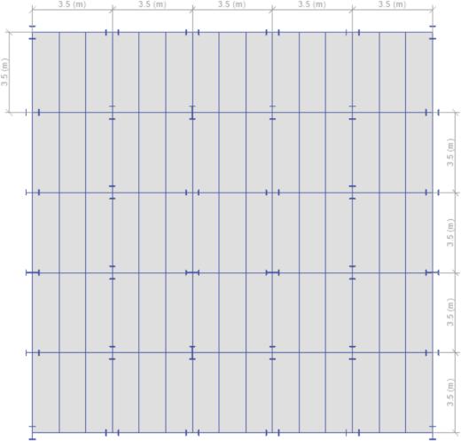
2.2 Plan View of Building
Figure1: PlanViewofBuilding
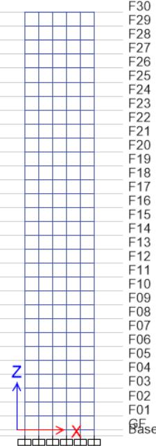
2.3 Building Elevation View
Figure3:With-outBracingSteelframeon20-degree Groundand30-DegreeSlope
Figure2:With-outBracingSteelframeonPlainGround and10-DegreeSlope
© 2024, IRJET | Impact Factor value: 8.226 | ISO 9001:2008 Certified Journal | Page354
Figure4:WithBracingSteelframeonPlainGround


Figure7:WithBracingSteelframeon30-degreeSlope
3. Result
3.1 Base Shear
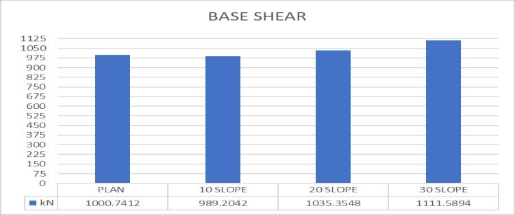
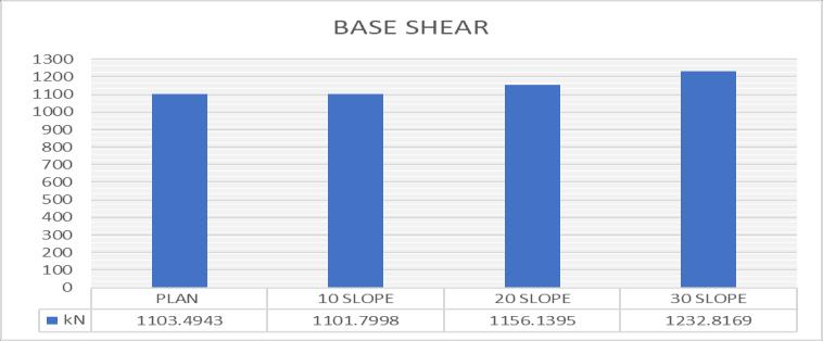
ChartNo.1.BaseShearWith-OutBracingSystem Frame(G+10)Structure
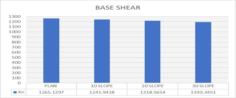
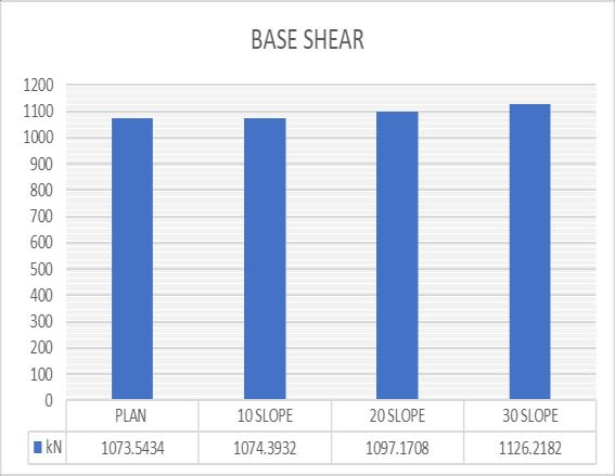
ChartNo.2.BaseShearWith-OutBracingSystem Frame(G+20)Structure
International Research Journal of Engineering and Technology (IRJET) e-ISSN:2395-0056 p-ISSN:2395-0072 Volume:11Issue:01|Jan2024 www.irjet.net BASE SHEAR 1050 1000 950 900 850 800 750 700 650 600 550 500 450 400 350 300 250 200 150 100 50 0
Figure5:WithBracingSteelframeon10-degreeSlope
Figure6:WithBracingSteelframeon20-degreeSlope
PLAN 10 SLOPE 20 SLOPE 30 SLOPE Kn 971.4445 971.8012 992.0219 1021.5324
© 2024, IRJET | Impact Factor value: 8.226 | ISO 9001:2008 Certified Journal | Page355

3.2 Natural Period of Oscillation
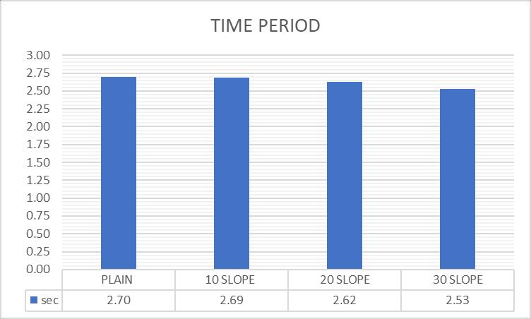
ChartNo.7Fundamental
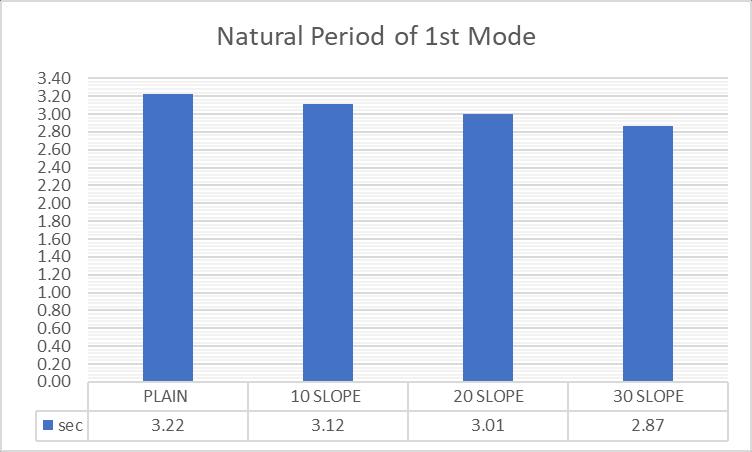
ChartNo.8NaturalPeriodofModeoscillationWith-Out BracingSystemFrame(G+20)Structure
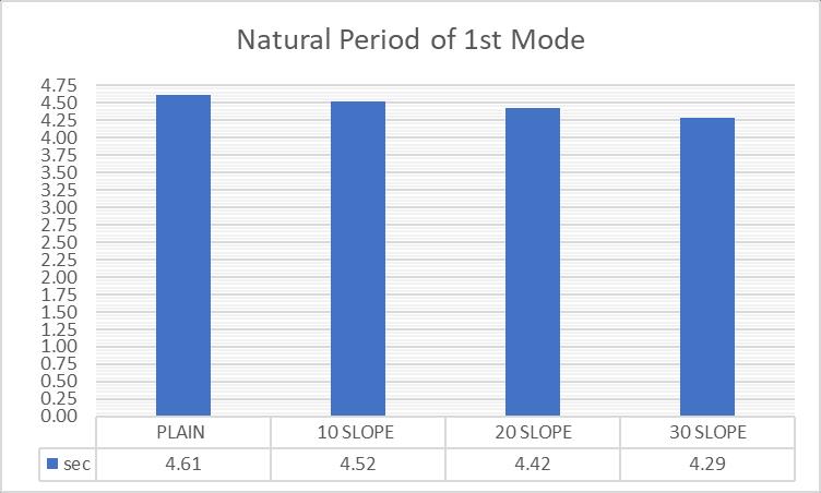
ChartNo.9NaturalPeriodofModeoscillationWith-Out BracingSystem
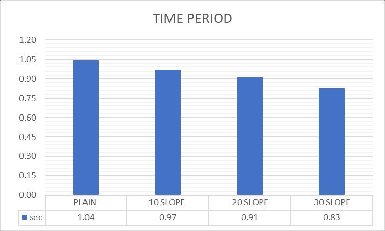
ChartNo.10NaturalPeriodofModeoscillationWith BracingFrameSystem(G+10)Structure
International Research Journal of Engineering and Technology (IRJET) e-ISSN:2395-0056 p-ISSN:2395-0072 Volume:11Issue:01|Jan2024 www.irjet.net
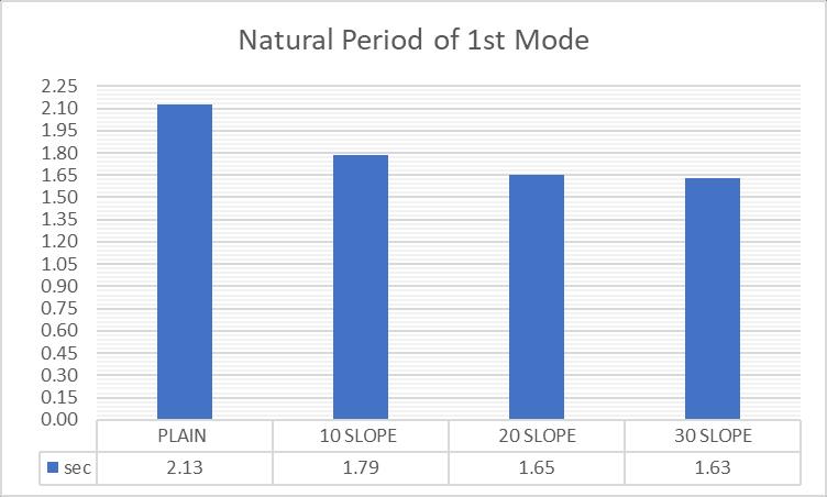
NaturalPeriodWith-OutBracing SystemFrame(G+10)Structure
Frame(G+30)Structure
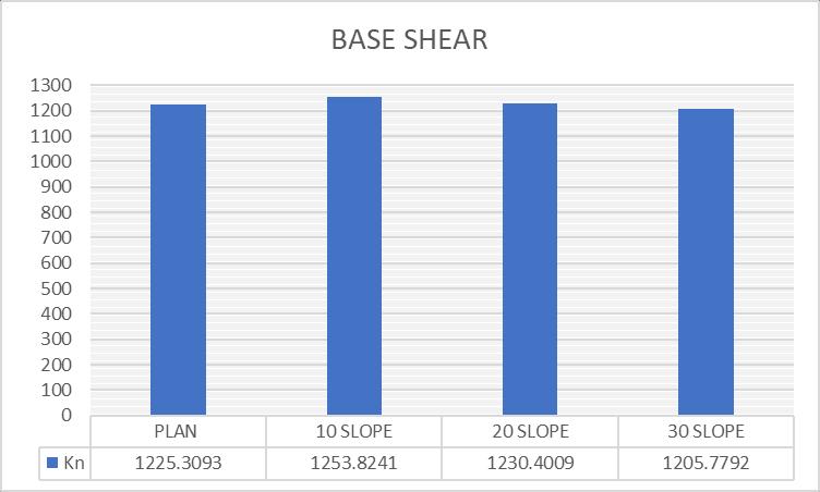
ChartNo.3.BaseShearWith-OutBracingSystem Frame(G+30)Structure
ChartNo.4.BaseShearwithBracingFrameSystem(G+10) Structure
ChartNo.5.BaseShearFramewithBracing(G+20) Structure
© 2024, IRJET | Impact Factor value: 8.226 | ISO 9001:2008 Certified Journal | Page356
ChartNo.6.BaseShearFramewithBracing(G+30) Structure

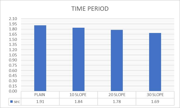
ChartNo.15
ChartNo.16
International Research Journal of Engineering and Technology (IRJET) e-ISSN:2395-0056 p-ISSN:2395-0072 Volume:11Issue:01|Jan2024 www.irjet.net
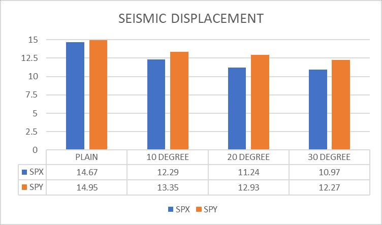
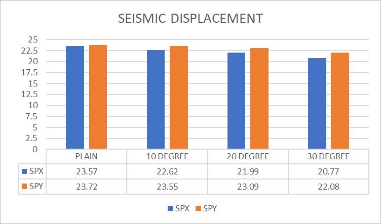
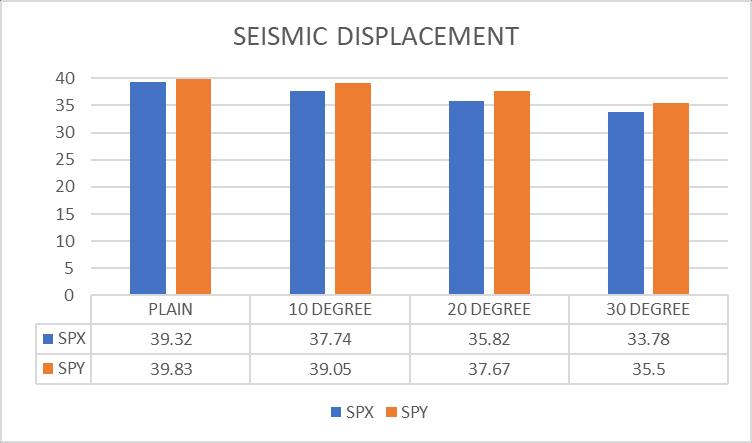
3.3 Maximum story Displacement for Seismic Load
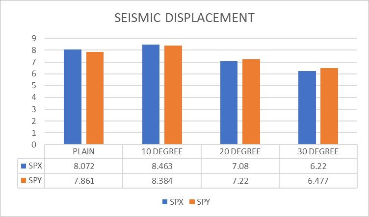
ChartNo.13SeismicDisplacementWith-OutBracing frameSystem(G+10)Structure
ChartNo.11NaturalPeriodofModeoscillationWith BracingFrameSystem(G+20)Structure
hartNo.12NaturalPeriodofModeoscillationWith BracingFrameSystem(G+30)Structure
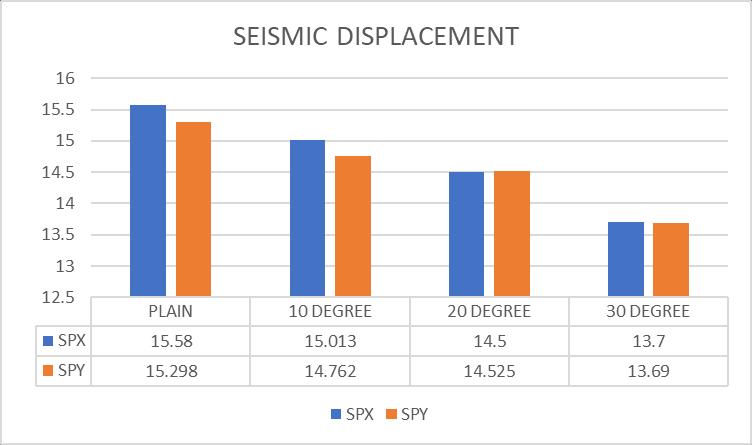
ChartNo.14SeismicDisplacementWith-OutBracing frameSystem(G+20)Structure
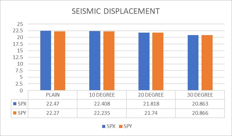
SeismicDisplacementWith-OutBracing frameSystem(G+30)Structure
SeismicDisplacementWithBracingframe System(G+10)Structure
© 2024, IRJET | Impact Factor value: 8.226 | ISO 9001:2008 Certified Journal | Page357
ChartNo.17SeismicDisplacementWithBracingframe System(G+20)Structure

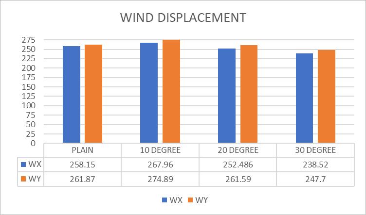
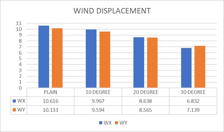
No.22
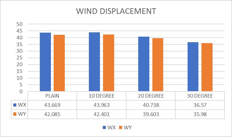
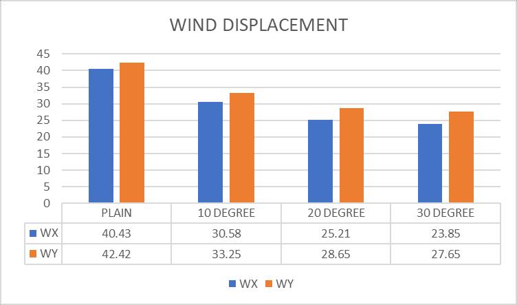
Chart No.23 Wind Displacement With Bracing frame System(G+20)Structure
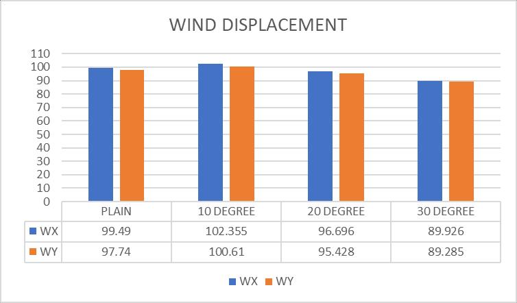
ChartNo.24WindDisplacementWithBracingframe System(G+30)Structure
International Research Journal of Engineering and Technology (IRJET) e-ISSN:2395-0056 p-ISSN:2395-0072 Volume:11Issue:01|Jan2024 www.irjet.net
3.4 Maximum story Displacement for Wind Load
WIND DISPLACEMENT 120 110 100 90 80 70 60 50 40 30 20 10 0 PLAIN 10 DEGREE 20 DEGREE 30 DEGREE WX 113.56 114.08 104.54 94.93 WY 116 08 118 8 WX WY110 68 100 67
ChartNo.19WindDisplacementWith-OutBracing frameSystem(G+10)Structure
ChartNo.20WindDisplacementWith-OutBracing frameSystem(G+20)Structure
ChartNo.18SeismicDisplacementWithBracingframe System(G+30)Structure
ChartNo.21WindDisplacementWith-OutBracing frameSystem(G+30)Structure
Chart
WindDisplacementWithBracingframe System(G+10)Structure
© 2024, IRJET | Impact Factor value: 8.226 | ISO 9001:2008 Certified Journal | Page358

4. Discussion
1. AsperIS1893,TheMassofparticipationis65%infirst theirmodeandstructureissafefromtorsion.
2. After analysis model, The Natural Period of mode Oscillation is Decrease, when Slope of structure is increased.
3. AllstructuralaresafeinTorsionalIrregularity.
4. . In G+10 and G+20 Bracing system the Base Shear is increased,Whentheslopeisincreased.
5. In G+30 the Base Shear is observed, The Base Shear is DecreasingbecauseoftheSeismicCoefficientislessthan 1.1%.
6. In G+10, G+20 with and with-out bracing structure it is observed that, The Base Shear is increased because of fundamentalnaturaltimeperiodisdecreased.Andalso, the weight of building is decreased when slope is increased
7. . In Natural Period of oscillation get 41% difference in with-out bracing system and with bracing system. If bracing system is applying the Natural Period of oscillationisdecrees41%.
8. Compare plain ground and sloping ground. The Natural Period of Oscillation is decreased. In G+10 with-out Bracingsystemaverage20%decreasedandwithBracing systemaverage12%decreased.WhereinG+20with-out BracingsystemandwithBracingaverage6%decreased. And in G+30 with-out Bracing system average 4% decreased and with Bracing system average 2% decreased.
9. ThewithoutBracingsystemG+10andG+20structureis safeindeflectionbutG+30isnotsafeinwinddeflectionit is cross the limit (H/500). The G+30 structure required Bracingsystem.
10. The wind load is increased when the slope is increased because as per topography factor (K3) is based on topographydimension.Whentheslopeisincreased(K3) factorisalsochange,at10-degreeslopethe4%forceis increased and at 20-degree and 30-degree slope 3.6% forceisincreased.
5. Conclusions
1. After comparison it is observed that G+10 and G+20 structurecanstablewith-outBracing but morethan20 storystructurerequiredBracingSystem.
2. InthiscaseG+30storystructureisbetterperformancein BracingSystem.
3. Comparison between Bracing system and with-out bracingsystem,ifweaddbracingsystemthenstiffnessof structure is increase and Because of increase stiffness, Decreasethemodeofoscillation.
4. Afteranalysisthemodel,theG+30with-outBracing systemstructureisunsafe.
5. Afteranalysisthemodel,observedthatwhentheslopeis increasedneedtoprovidedmorestiffnessforcolumnup toslopingarea.
6. It is observed that when the slope is increased then deflectionofstructureisalsoincreasedinGravity(DLLL).
REFERENCES
[1] Dhiraj Ahiwale et al. – “Seismic Response Assessment of Steel Frame Step-back Building for Different Fluid Viscous Dampers” – https://www.researchgate.net/ publication/344269992,Sep2020
[2] NaveenV&MNHegde–“DynamicAnalysisofsetback steel moment resisting frame on sloping ground with different types of bracing system” – International ResearchJournal of Engineering and Technology, Vol. 04Issue09,June-2017.
[3] Panthak tayade & Dr. Swati Ambadkar – “Analysis and DesignofG+6buildingindifferentSeimicZoneofIndia” –International Journal for Research in Applied Science and Engineering Technology, ISSN 2321-9653 June2020.
[4] Swapnamol Chacko eta al – “Optimization of Seismic ResponsebySteelframestructureonslopingground”–International Research Journal of Engineering and Technology–ISSN2395-0056June2022.
[5] Amruta Kadu – “Seismic Analysis of RCC and Steel buildingonslopingground” – International Journal for Research in Applied Science and Engineering TechnologyISSN2321-9653July2021.
[6] ReferIScode:-IS800:2007
...IS1893:2016 IS16700:2017
...IS875(Part1,Part2andPart3)
[7] ReferBooks:-SteelStructuresbyB.C.PunmiaAshok Jain,ArunJain
DesignofSteelStructuresbySK DuggalStructuralAnalysisbyRC Hibbeler
BIOGRAPHIES

Mr.SiddheshBholanathWavalehas completed his BE from Mumbai University. He is currently pursing hisMEstructuralEngineeringfrom MGM college of Engineering and Technology,kamothe, Panvel. Hehas totalworkexperienceof5yearsand is currently working at CBM engineercompanyinhigh-risemultistoryproject.
International Research Journal of Engineering and Technology (IRJET) e-ISSN:2395-0056 p-ISSN:2395-0072 Volume:11Issue:01|Jan2024 www.irjet.net
© 2024, IRJET | Impact Factor value: 8.226 | ISO 9001:2008 Certified Journal | Page359


