
Effect of Camber and Angles of Attack on Airfoil Characteristics
Rajat Rajnish1, N.S. Thakur
, Priyanshu Kumar Pant3
Hamirpur
1 PG Scholar, Center for Energy Studies, N.I.T Hamirpur, Himachal Pradesh, India
2Professor, Center for Energy Studies, N.I.T Hamirpur, Himachal Pradesh, India
3PG Scholar, Dept. of Mathematics and Scientific Computing, N.I.T Hamirpur, Himachal Pradesh, India
Abstract -Research is underway to enhance the aerodynamic efficiency of air vehicles, wind turbines, and automobiles through diverse approaches. This study employs a comprehensive analysis of three criteria that define the shape, including the camber, position of the camber, and angle of attack of the airfoil. The objective is tounveil theoverall design space Thisstudy throwslight on the relation and impact of airfoil parameters on airfoil characteristics. This research shows the fully coupled impact of camber, position of camber, and angle of attack on lift coefficient and drag coefficient. These results show the efficiency and performance of airfoils with varying chosen parameters and show the optimized airfoils in the regionofstudy.
Keywords: Airfoil, Computational fluid dynamics, Efficiency,Cl/Cdratio,Aerodynamicsperformance
1.INTRODUCTION
Airfoil shape plays the most important role in the overall performance ofaerodynamic bodies;a lotofgreatstudies have been done to create specific airfoil shapes for the desireddesigncondition.Differentshapesoftheairfoilare used according to the needs of industries for their applications like in helicopters, micro aerial vehicles[1], compressors, wind turbines, and many more areas. Airfoils have very essential characteristics that are lift, drag,andairfoilefficiency.Thesefeaturesspecifyhowwell an airfoil performs in the specific application for which it is used. Analyzing the characteristics of the airfoil and theirrelationshipwitheachotherwilldirectustousethe optimized airfoil for specific applications Airfoils have been researched for various purposes for a long time for various industries like aircraft, renewable industry for wind energy production, compressors, and much more. Mostly airfoils are the key element used by these industries for their applications, which means a goodperforming airfoil is needed. A lot of research has been done on airfoil parameters like shape, structure, etc. The work done on the optimization of airfoil shape for wind turbine application[2]. Work by M. Rasoul Triandaz[3] aboutthe effectofairfoil shapeson powerperformance if VWAT is much appreciable, 126 airfoils were analyzed. A lot of research has been there on methods for the advancement of airfoil shape sat trailing edge [4], [5], [6]Solidity effect on the performance of variable-pitch
VAWT[7]. Study on surface modification on aerodynamic characteristicsofairfoilDU06W200[8] About20airfoils wereexaminedfortheperformanceofanH-rotorDarrieus turbinebyMHMohammad[9] ResearchDevelopmentand Testing of an Unconventional Morphing Wing Concept with Variable Chord and Camber[10], [11], [12], airfoil thickness effect on dynamic stall characteristics of High‐Solidity Vertical Axis Wind Turbines Researchers have innovated camber morphing mechanisms employing smart materials[13], [14]. These mechanisms enable the adaptive adjustment of airfoil curvature, enhancing aerodynamic efficiency and performance in various applications,includingaerospaceandwindenergy.Mostly the area of attention is on the performance of airfoils in various applications, optimization methods for obtaining good-performing airfoils, and morphing techniques for airfoils. No doubt a large number of airfoils is being analyzed but mostly symmetrical and just by varying thickness and taking other effective parameters as constant. There is very little attention given to the dependency of parameters on each other and their relationship with the characteristics of airfoils. The research gap comes out of the studied literature on the analysis of asymmetric airfoils with varying camber, varying position of camber, and varying angle of attack (AoA)byestablishingco-relationbetweenthemwhichwill show the performance of airfoil and dependency of parametersoneachother.Thisstudyaimstoshedlighton how structural characteristics affect the aerodynamic performanceofasymmetricalairfoils. 16NACAfourdigits modified asymmetric airfoils are analyzed by varying camber angles and their position concerning chord length(C),rangeshowninTable1. Thecharacteristics,lift and drag coefficient along with the Cl/Cd ratio are analyzed and co-relations are shown between these characteristics ThisanalysisisperformedatReynoldsNo. (Re) 6.84*105 and velocity V=10 m/s. The fluid used in CFD simulation is air having a density of 1.225 kg/m3 . Varying the camber and its position provide major aerodynamicadvantagesby allowingforuniqueandlarge shape modifications to accommodate varied flight situations, in turbines for efficient power generation, and many other applications where airfoils are used for specific purposes to enhance the performances. These analysesshowchangesinairfoilefficiencyandrelationsof airfoil characteristics with each other. Notably, the drag and lift coefficient parameters (Cd) and (Cl)are critical,
International Research Journal of Engineering and Technology (IRJET) e-ISSN: 2395-0056 Volume: 11 Issue: 01 | Jan 2024 www.irjet.net p-ISSN: 2395-0072 © 2024, IRJET | Impact Factor value: 8.226 | ISO 9001:2008 Certified Journal | Page729
2
1 2 3National Institute of Technology
***
making morphing wings a viable strategy for improving airfoil performance. The thickness (t =24%C), leadingedge radius index (I=4%C), and position of a thickness (xt=30%C)aretakenconstant.
1.1 NACA 4-Digit Airfoil
The NATIONAL ADVISORY COMMITTEE FOR AERONAUTICS (NACA) produced NACA airfoils, which are airfoil forms for aircraft wings. A series of numerals followingthe term NACA describes theshape of the NACA airfoils.The NACA Four-Digit Series was the first family of airfoils to be constructed with thismethod. The maximum camber (M) in the percentage of the chord (airfoil length) isspecifiedbythefirstdigit,themaximumcamberposition (P) in tenths of the chord is indicated by the second, and the maximum thickness (t) of the airfoil in the percentage of the chord is given by the final two digits. For example, the NACA 2415 airfoil has a maximum thickness of 15% withacamberof2%positioned40%backfromtheairfoil leadingedge(or0.4c).Withthesem,p,andtvalues,wecan usethefollowingrelationshipstogetthecoordinatesofan airfoil[15]
yc= x2 ) (0≤x<P)
yc= M/(1-P)*(1-2P+2Px-x2) (P≤x≤1)
Themodifiedairfoilprofilecoordinatesaregeneratedwith the help of Open VSP software. This helps us to plot 2-D modified airfoils with various camber and position changes.
1.2 Naming Scheme of NACA 4-Digit Modified Airfoil
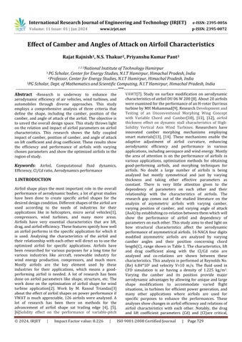
The airfoil will be identified with the name NACA MPt-Ixt where I is the leading edge radius index and xt will show the position of maximum thickness of the airfoil. All the parameterlocationsareshowninFig.1.
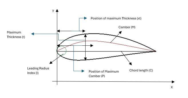
Table -1: Range
analyzed
inpercentage(%) Chordlength(C)=1meter
Parameters
The angle of Attack (AoAindegree)
2. Design and Meshing
NACA MPt-Ixt airfoils are designed in Open VSP software. The number of airfoils analyzed is 16 having different parametersvaryingthecamberandcamber’slocation.The chordlengthoftheairfoilis1meter,andtheLeading-edge radius index (I) is 4% of C. The thickness is constant i.e. 24% of C and the position of thickness is taken at 30% of C. The shape of all 16 profiles is shown in Fig.2. The semicircular and rectangular domain known as C type mesh domain is used having 200000 elements inside the mesh. The C type is better to use for 2-D surfaces as we can produce structured cells and uniform structures of cells near complex geometry. To accurately estimate flow near walls, particularly for airfoils with highpressuregradients, thestructured mesh is more frequently used around these intricate geometries. Moreover,ituseslessmemoryandtimethanunstructured grids. The simulations were carried out in Ansys Fluent v2023R2.ThetypeofmeshanddomainisshowninFig.3.Z

International Research Journal of Engineering and Technology (IRJET) e-ISSN: 2395-0056 Volume: 11 Issue: 01 | Jan 2024 www.irjet.net p-ISSN: 2395-0072 © 2024, IRJET | Impact Factor value: 8.226 | ISO 9001:2008 Certified Journal | Page730
Fig -1:Shapeparameterofasymmetricairfoil
of
parameters
Camber (M) Position of camber(P)
2 20 0 3 30 5 4 40 10 5 50 15
Fig -2:AnalyzedAirfoilProfiles

4. Results
4.1 Correlation Matrix at Different AoA.
A correlation matrix is important because it can reveal relationships, influence the selection of variables, and improve a general understanding of the dataset. The correlation matrix in Fig.4showsthe relation of Cl,Cd, M, andPatdifferentAoAwitheachother Factor1showsthe impact of the dependency is highest, factor 0 shows the impact of no dependency, and the negative factor shows theinversedependencyoftheparameterswitheachother.
3. Computational Settings
The simulations are based on the URANS SST model. The turbulence model used in this study was chosen after a thorough critical examination of seven commonly used Reynolds-averaged eddy-viscosity turbulence models in three separate and diverse experimental setups. [66 refs, 15models].WechoosetheTransitionSSTmodelbecauseit gives the most accurate results with experimental results for NACA 2412 airfoil.[16] as shown in chart -1. The transition SST model combines the k-ε model for the free stream and the k-ω model for flow nearwalls. The inlet conditions used for turbulence are intermittent is 1, turbulence intensity is 5%, and turbulence viscosity ratio is 10. The outlet condition is set as a pressure outlet. The coupled scheme is used for pressure velocity coupling all with second-order spatial discretization. Several 1000 iterations were employed for better convergence of simulationresults.


International Research Journal of Engineering and Technology (IRJET) e-ISSN: 2395-0056 Volume: 11 Issue: 01 | Jan 2024 www.irjet.net p-ISSN: 2395-0072 © 2024, IRJET | Impact Factor value: 8.226 | ISO 9001:2008 Certified Journal | Page731
Fig -3:SchematicmeshandDomainofAirfoil
Chart -1:ClcomparisonwithCFDvsExperimentofNACA 2412
Lift Coefficient AoA Lift Coefficient Comparison CFD EXP No Slip Wall U∞ Outlet

(b).Cd correlation with P and M
Cdhas a correlationwithM of0.82atAoA0 degreesand 0.99 at 5 degrees then further it decreases to 0.70 at 15 degrees. The value of Cd is all positive with M as the relation is directly proportional with (M), but the impact of correlation decreases as we increase AoA from 5-15 degrees. The impact of the correlation of Cd with the positionofcamber(P)ishighestat0degreesi.e.0.50,but furtherdecreasesto15degreeswhichare-.40.Thisshows thatwithanincreaseinthePto50%C,theinverserelation starts at 10 degrees which means after 10 AoA if we furtherincreasePwilldecreasetheCd.
(c). P and M correlation
The parameters P and M show the impact of 0 which means they do not establish any relation and do not have any relation with each other. This is because P and M are independent parameters that do not affect each other. Theyarevaluessetbyindividualstodesigntheairfoil,but they both impact the characteristics such as Cl, Cd, and efficiencyoftheairfoil.

.2 Effect on Cl and Cd with varying M and P
(a). Cl correlation with Cd, M, and P
Cl hasa correlationwith Cd of0.89fromAoA0-10,which climbs to 0.97 at AoA 5 and subsequently decreases to0.62 at AoA 15. This shows that Cl and Cd have a directly proportionalrelationtill10degreesifClwillincreasethen Cdwillalsoincrease.ThecorrelationofClandCdoneach other has a high impact and after AoA 15 will inversely affect each other. The impact of the correlation of Cl with camber (M) at 0 degrees is highest at 0.99 but starts to decreaseasweincreaseAoA.At15degreesClwillhavean inverse relation i.e. if we increase AoA then Cl will decrease if we increase the camber. The Cl relation with thecamber(P)positionincreasesasweincreaseAoA.At0 degreestheimpactofcorrelationofClwithPis0.11which further increases to 0.66 at AoA 15 degrees. This shows the Cl will increase as we increase the position of the camberto5%ofCwithincreasingAoAvalue.
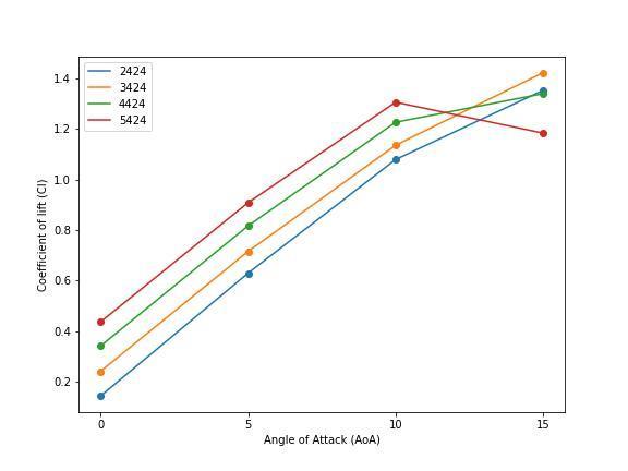
Fig 4a, 4e. Shows the effect of varying camber with AoA and keeping the position of camber constant. At P=20%C, the Cl of the airfoils increases till 10 degrees AoA, but profile 5224 has a sudden drop in Cl, and 3224 performs the best among the profiles in Fig 5a. The difference of Cl between 3224 and 5224 is 20.11% at 15 degrees. This shows that the Cd for 3224 is less than 5224 at a high angle of attack i.e. 15 degrees, the difference between Cd of 3224 and 5224 is 45.18%. Airfoil 2224 and 4224 have gradually increased in Cl to 15 degrees AoA. Both have almost the same Cl at 15 degrees with a difference of 1.73%.Fig4b,4fshowsatP=30%CtheClofalltheprofiles increasesupto15degreesAoAexceptprofile5324whose Clincreasesto10butdecreasesatAoA15degrees.Airfoil 4324hasthehighestCland2324hasthelowestClatAoA 15degreeswithadifferenceof17.02%.Theairfoils5324 and 3324 are almost at the same Cl at 15 degrees with almostadifferenceof9%.Duetocamberchangethedrag on airfoil 5324 is the highest. In Fig 4c, 4g at P=40%C, airfoils almost show the same behavior as n Fig 4a, 4e Cl difference between airfoil 3424 and 5424 is 16.82. In Fig 4d,4hatP=50%Cshowsthatthereisagradualincreasein Cl andCdofall profilesand very littledifference between Clofairfoils.TheClshowstheconvergingbehavioratAoA 15degreeswhenwetakeP=50%C.Thesegraphsshowthe effectsofvaryingcamberandpositionofcamberonCland Cd, which helps identify the airfoil that can give good performanceconcerningconditionsweneed.
International Research Journal of Engineering and Technology (IRJET) e-ISSN: 2395-0056 Volume: 11 Issue: 01 | Jan 2024 www.irjet.net p-ISSN: 2395-0072 © 2024, IRJET | Impact Factor value: 8.226 | ISO 9001:2008 Certified Journal | Page732
Fig -4:CorrelationmatrixatDifferentAoA.


International Research Journal of Engineering and Technology (IRJET) e-ISSN: 2395-0056 Volume: 11 Issue: 01 | Jan 2024 www.irjet.net p-ISSN: 2395-0072 © 2024, IRJET | Impact Factor value: 8.226 | ISO 9001:2008 Certified Journal | Page733
Fig -4a:EffectonClwithvaryingcamberatP=20%C
Fig -4b:EffectonClwithvaryingcamberatP=30%C
Fig -4c:EffectonClwithvaryingcamberatP=40%C
Fig -4d:EffectonClwithvaryingcamberatP=50%C
Fig -4e:EffectonCdwithvaryingcamberatP=20%C
Fig -4f:EffectonCdwithvaryingcamberatP=30%C


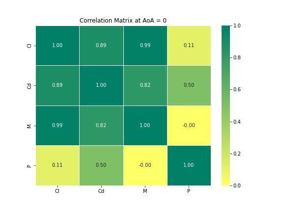
4.3 Impact of AoA on Cl and Cd of Airfoils
Fig5depictsthattheCdoftheairfoilsincreasesgradually andwithalmost someconsistency with change inAoA till 10 degrees, but for AoA 15 degrees the sudden increases and decreases in Cd the pattern not consistent which is due to the generation of the wake region which gives rise to stall conditions due to these stall conditions the lift starts to decrease at high angles of attacks. The Cd for 5224isthehighestatAoA15degreesandtheClislowfor thisatAoA15degrees.Thereisanincreaseofalmost20% in Cl from airfoil 2224-5524 at 15 degrees, 16.47% at 10 degrees,35.21%at5degrees,and67.11%at)degreesAoA

International Research Journal of Engineering and Technology (IRJET) e-ISSN: 2395-0056 Volume: 11 Issue: 01 | Jan 2024 www.irjet.net p-ISSN: 2395-0072 © 2024, IRJET | Impact Factor value: 8.226 | ISO 9001:2008 Certified Journal | Page734
Fig -4g:EffectonCdwithvaryingcamberatP=40%C
Fig -4h:EffectonCdwithvaryingcamberatP=50%C
Fig -5:EffectonCdwithvaryingcamberatP=50%C
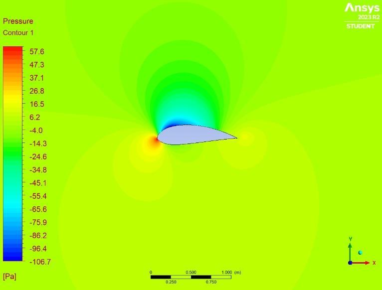
Fig -5a:PressureContourofairfoil4524at5degrees AOA

4.4 Efficiency of Airfoils
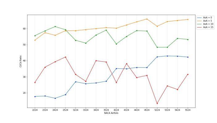
Efficiency is defined by L/D ratio or Cl/Cd ratio. The higher the ratio more efficient will be the airfoil in the aspect of performance, which means the airfoil has the high lift and least drag which is the most required condition of airfoil.Airfoil4524 at AoA 5 degrees has the highest Cl/Cd ratio i.e. 65.98 and Airfoil 5524 at AoA 5 degrees has a value of 65.65 which is very close to airfoil 4524’sratio.Airfoil5224hastheleastratioi.e.
5. CONCLUSIONS
Withinthisstudyrangetheconclusionsareasfollows:
Fromthecorrelationmatrix itsaysthatthereis a relation between Cl and Cd which is directly proportional up to AoA 10 degrees and inversely proportionalafter10degrees.
The Cl decreases if we only change the camber (M) and take other parameters constant, but Cl increases when we change the position of the camber(P).
PandMareindependentofeachotheranddonot impacteachother.
TheCl increasesgraduallyforall airfoils upto 15 degrees, but the airfoil of camber 5%C Cl decreases after 10 degrees except forthe 5524 airfoils The Cd for all airfoils increases as we increaseMandP.
Airfoil 5524 has the highest Cl among studied airfoilsat15degreesAoAandairfoil2224hasthe leastCl.
Twoairfoils4524and5524arethemostefficient inthestudiedregion having Cl/Cd ratiosof65.98 and 65.65 respectively. Airfoil 5224 has the lowestCl/Cdratioof13.46.
Finally,thestudyemphasizeshowthetwoshape-defining parameters of asymmetric airfoils interact to affect their efficiency and characteristics. It underlines that isolating one parameter while leaving others constant can lead to inconclusive results. The study shows that changing the parameters leads to changes in characteristics and efficiency,Thecorrelationmatrixstudyalsoshowsthereis also the relation of characteristics and parameters with each other which shows the behavior of characteristics witheachother.
International Research Journal of Engineering and Technology (IRJET) e-ISSN: 2395-0056 Volume: 11 Issue: 01 | Jan 2024 www.irjet.net p-ISSN: 2395-0072 © 2024, IRJET | Impact Factor value: 8.226 | ISO 9001:2008 Certified Journal | Page735
Fig -5b:PressureContourofairfoil5524at5degreesAOA
Fig -5c:PressureContourofairfoil5224at15degrees AOA
13.46.
Fig -7:Cl/CdofAirfoils
REFERENCES
[1] N.S.K.Teja,A.Teja,J.S.Harsha,S.Ganesh,andK.V Ramana, “OPTIMIZATION OF MICRO AIR VEHICLE AIRFOIL.”[Online].Available:http://www.ijret.org
[2] A.F.P.Ribeiro,A.M.Awruch,andH.M.Gomes,“An airfoil optimization technique for wind turbines,” Appl Math Model, vol. 36, no. 10, pp. 4898–4907, Oct.2012,doi:10.1016/j.apm.2011.12.026.
[3] M. R. Tirandaz and A. Rezaeiha, “Effect of airfoil shape on power performance of vertical axis wind turbines in dynamic stall: Symmetric Airfoils,” Renew Energy, vol. 173, pp. 422–441, Aug. 2021, doi:10.1016/J.RENENE.2021.03.142.
[4] P. L. Bishay et al., “Development of an SMA-based camber morphing UAV tail core design,” Smart Mater Struct, vol. 28, no. 7, p. 075024, Jul. 2019, doi:10.1088/1361-665X/ab1143.
[5] H. Li, L. Liu, T. Xiao, and H. Ang, “Design and simulative experiment of an innovative trailing edge morphing mechanism driven by artificial muscles embedded in skin,” Smart Mater Struct, vol. 25, no. 9, p. 095004, Sep. 2016, doi: 10.1088/0964-1726/25/9/095004.
[6] L.Hongpeng,W.Yu,Y.Rujing,X.Peng,andW.Qing, “Influence of the modification of asymmetric trailing-edge thickness on the aerodynamic performance of a wind turbine airfoil,” Renew Energy, vol. 147, pp. 1623–1631, Mar. 2020, doi: 10.1016/J.RENENE.2019.09.073.
[7] M.T. Parra-Santos,C. N.Uzarraga,A.Gallegos, and F. Castro, “Influence of Solidity on Vertical Axis Wind Turbines,” International Journal of Applied Mathematics, Electronics and Computers, vol. 3, no. 3,p.215,Jun.2015,doi:10.18100/IJAMEC.42848.
[8] O. A. Zargar et al., “The effects of surface modification on aerodynamic characteristics of airfoil DU 06 W 200 at low Reynolds numbers,” International Journal of Thermofluids, vol. 16, p. 100208, Nov. 2022, doi: 10.1016/J.IJFT.2022.100208.
[9] M. H. Mohamed, “Performance investigation of Hrotor Darrieus turbine with new airfoil shapes,” Energy,vol.47,no.1,pp.522–530,Nov.2012,doi: 10.1016/j.energy.2012.08.044.
[10] W. R. Kang, E. H. Kim, M. S. Jeong, I. Lee, and S. M. Ahn, “Morphing wing mechanism using an SMA wire actuator,” International Journal of Aeronautical and Space Sciences, vol. 13, no. 1, pp. 58–63,2012,doi:10.5139/IJASS.2012.13.1.58.
[11] T. Majid and B. W. Jo, “Comparative Aerodynamic Performance Analysis of Camber Morphing and ConventionalAirfoils,” Applied Sciences,vol.11,no. 22, p. 10663, Nov. 2021, doi: 10.3390/app112210663.
[12] J. Zhang et al., “Aeroelastic model and analysis of an active camber morphing wing,” Aerosp Sci Technol, vol. 111, p. 106534, Apr. 2021, doi: 10.1016/J.AST.2021.106534.
[13] H.Basaeri,A.Yousefi-Koma,M.R.Zakerzadeh,and S. S. Mohtasebi, “Experimental study of a bioinspired robotic morphing wing mechanism actuated by shape memory alloy wires,” Mechatronics, vol. 24, no. 8, pp. 1231–1241, Dec. 2014,doi:10.1016/j.mechatronics.2014.10.010.
[14] D. ; Keidel, J. ; Sodja, N. ; Werter, R. ; De Breuker, and P. Ermanni, “Development and Testing of an Unconventional Morphing Wing Concept with VariableChordandCamber,”APA,2015.
[15] “A-1AppendixAGeometryforAerodynamicists.”
[16] H.AbbottandAlbertE.Von, Theory of Wing Sections -IraH.AbbottandAlbertE.VonDoenhoff.
International Research Journal of Engineering and Technology (IRJET) e-ISSN: 2395-0056 Volume: 11 Issue: 01 | Jan 2024 www.irjet.net p-ISSN: 2395-0072 © 2024, IRJET | Impact Factor value: 8.226 | ISO 9001:2008 Certified Journal | Page736