International Research Journal of Engineering and Technology (IRJET) e-ISSN:2395-0056

Volume: 10 Issue: 08 | Aug 2023 www.irjet.net p-ISSN:2395-0072

International Research Journal of Engineering and Technology (IRJET) e-ISSN:2395-0056
Volume: 10 Issue: 08 | Aug 2023 www.irjet.net p-ISSN:2395-0072
1Assistant Professor, Department of Civil Engineering, Adichunchanagiri Institute of Technology, Chikkamagaluru
2Assistant Professor, Department of Civil Engineering, Adichunchanagiri Institute of Technology, Chikkamagaluru
3 P G Student, Department of Civil Engineering, Adichunchanagiri Institute of Technology, Chikkamagaluru ***
Abstract Civil Engineers are facing a great challenge in structural designing. The design must fulfil various parameters which include economical structure, durability and serviceability. But taking these points in mind it becomes very difficult for an Engineer to fulfil all these requirements at a time when a design is performed manually. This dissertation presents research on digital tools used in civil engineering and comparing their results by taking in mind the requirements of the above points. In this research process a building is taken for analysis and design on well-known Software ETABS. Based on the results taken from the Software some comparison is done with manual analysis for residential building.
Nowadays every designing organisation is using these Software but there is a question mark to which software we must go for designing. The parent organisations which have developed these designing tools promote their Software by showing all the positive points. In addition to this they are trying to fill all the loop holes which they found in their products but it will never happen that another developing company will put the points in light what the negative points are there in existing products. They keep on improving to deliver their best. In this project work I will present the difference for future users to which tool you must go through to acquire your needs. I am not saying that some products are not ok at all. I have designed a residential building with proper loading which is being designed on both ETABS. Manual calculations make it crystal clear the difference between the Software.
Key word: Etabs Software, structural design, residential building.
In designing an economical and stable RCC framed building for residential use involves a comprehensive approach, considering both computer-based software tools like CSI-Etabs and manual calculations. Here’s a generaloutlineofthestepsismightundertake.
Determine the various loads acting on the structure, including dead loads, live loads, wind loads and seismic loadsbasedonthelocalbuildingcodesandstandards.
Choose an appropriate structural system, such as a reinforced concrete(RCC)framedstructure,considering factors like material availability, local construction practicesandthebuildingsintendeduse.
3.
Utilize the Etabs software to perform a detailed structural analysis of the building. Input the building geometry,materials,loadsandconstraints.Thesoftware will provide a various output including structural reactions,internalforcesanddeflection.
4. Manual calculation validation
Perform manual calculations for critical section of the building, such as beams, columns and slabs to validate theresultsobtainedfromthesoftwarethishelpsensure theaccuracyoftheanalysisanddesign.
Based on the analysis design, design the various structural element such as beams, columns, slabs and footings. Ensure that they are sized appropriately to carry the calculated loads and satisfy the safety and serviceabilitycriteria.
6. Reinforcement details
Provide detailed reinforcement layouts for each structural element, ensuring proper cover, spacing and arrangements of reinforcement bars. This is crucial for thestructuralintegrityanddurabilityofthebuilding.
Abhay Guleria (2014): it’sinterestingtoobservethatin the analysis of a multi-storey building, the storey
overturning moment varies inversely with the storey height. Additionally, the similarity in between L shape and I shape buildings regarding overturn moment in noteworthy. This insight emphasizes the importance of considering both dynamic factor during analysis and design of multi-storey buildings, contributing to better understanding and optimization of their structural performance.
Varikuppala Krishna et.al (2015): Absolutely, considering the layout and design of a multi-storey building based on natural factors such as sun light and wind direction can have significant benefits. Using light weighconcreteandmaterialsisindeedasmartapproach to reduce the dead load of the structure. This reduction in dead load allows structural designer to optimize the sizingofloadbearingelementslikecolumnsandfootings it not only improves the overall structural efficiency but also contributes to cost saving and potential shorter constructiontime.
Sayyed Feroz Sikander et.al (2019): this study deals the analysis and design of an apartment building having G+10 storeys are done by using ETABS V-15.2 software. Which proved to premium of great potential in the analysis and the design of various section the structural element like RCC, shear wall and retaining wall are provided. As per soil investigation report, an isolated footing provided the various difficulties encountered in the design process and various constraints faced by the structural engineers in designing up to an architectural drawingwerealsounderstood.
Shivkumar Deshmukh and Nithesh Kushwaha (2020): the study compares the analysis design of structuraldifferentshapesthatincludessquares,H,plus and T-shape. Displacement, drift, shear and bending moments are compared and displacement is found maximum in T-shape and minimum in square. In comparison to other shapes, square shape shows least storey drift. Simplegeometrical shapeattractslessforce andperformancewell.
Chinmay Padole et.al (2021): thestudywastoevaluate the variations percentage increase in each floor of particularbeamandcolumnintheanalysisanddesignof G+4ofresidentialbuildingusingETABS.Thepercentage increaseinaxialloadandbendingmoment,ofeachfloor and that of the front column, central columns and back columnsandbeamofright,centreandbackofeachfloor. Later concluding the analysis to be safe as the variation didn’t exceed 10% after evaluating all the bending moment and axial loads and taking the difference and convertingintopercentage.
The project provided to us is completed performing each section works mentioned in the contents before the following stages are involved in the analysisanddesign
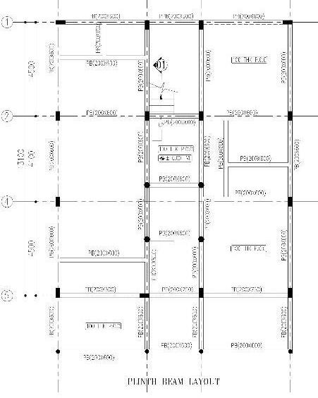
The arrangements of beams, Columns, Balcony slab, Room floors are done according as the figures shown below.Storeyheightofallfloorsistakenas3200mm.
Buildingtype :RCCFramed
Structuralsystem :ResidentialBuilding
Plinthareacovered :145sqm
Column : 200*200mm, 200*450mm & dia 280mm.
Beam :200*350mm, 200*400mm, 200*600mm, 200*750mm, 200*900mm,&200*1200mm.
Slab :125mm,150mm&200mm.
Typeoffoundation :IsolatedFooting.
No.ofstorey :3
Wall :200mm
Typeofsubsoil :ZoneII
PLAN LAYOUT:
International Research Journal of Engineering and Technology (IRJET) e-ISSN:2395-0056
Volume: 10 Issue: 08 | Aug 2023 www.irjet.net p-ISSN:2395-0072
Here the analyzed results of G+2 residential building fromETABSsoftwarehavebeentabulatedanddiscussed about the behavior of the structure the parameter considered from the analysis of G+2 multistorey structureisdefinedbelow
Base Reaction: it is defined as the horizontal reactions atthesupports.Itisrepresentedintermof'kN’.
Table.BaseReactioninkN
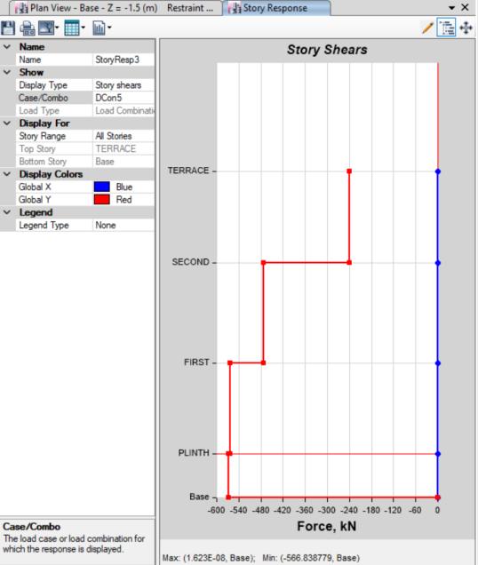
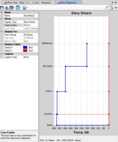
Storey Shear: the storey shear is defined as sum of design lateral forces at all level above the storey under consideration.Itisrepresentedintermof‘kN’.
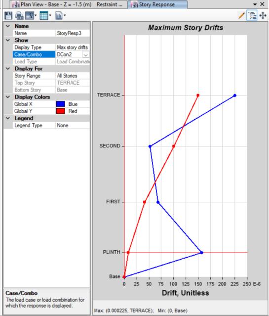
Storey Drift:thedriftisdefinedasratioofdisplacement of two consecutive floors to height. The maximum permissible drift is limited to 0.004 times the height of the storey. It is very important term used for research purpose an earthquake engineering. The storey drift in any storey due to maximum specified design lateral force,withpartialloadfactorof1.
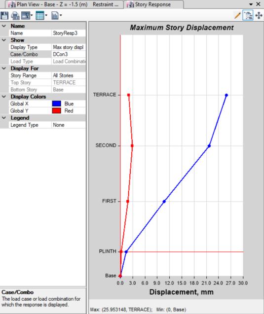
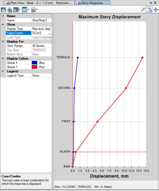
Storey Displacement: it is defined as the displacement of the storey with respect to the base of the structure. The maximum permissible displacement is limited to height of the building by 500(H/500) and it is representedintermof‘mm’.
International Research Journal of Engineering and Technology (IRJET) e-ISSN:2395-0056
Volume: 10 Issue: 08 | Aug 2023 www.irjet.net p-ISSN:2395-0072
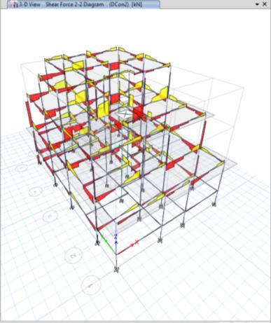
Shear Force:SFisappliedperpendiculartoasurface,in oppositiontoanoffsetforceactinginoppositedirection. Thisresultsinashearstrain.Insimpleterm,onepartof thesurfaceispushedinonedirection,whileanotherpart of the surface pushed in the opposite direction. It is representedintermof‘kN’.
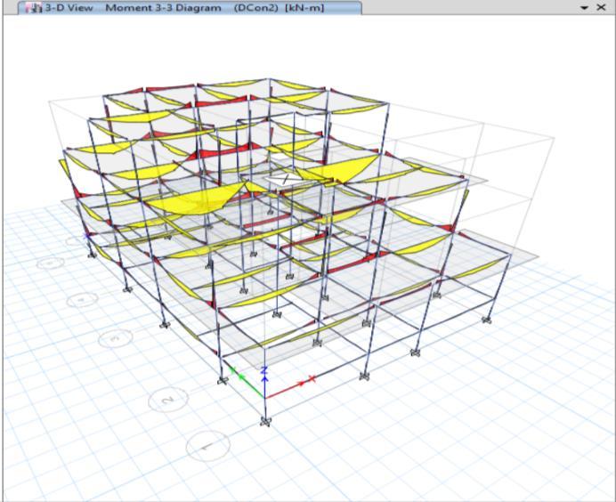
Bending Moment:BMisameasureofthebuildingeffect thatoccurswhenanexternalforceormomentisapplied toastructuralelement.Thisconceptisveryimportantin structural engineering as it can be used to calculate whereandhowmuchbendingmaybeoccurwhenforces areapplied.Itisrepresentedintermof‘kN-m’.
If any beam fails, they dimension of the beam and column should be changed and reinforced detailing canbeproduced.
Analyse and design and results obtained from ETABSarecomparedwiththatofmanualdesignthe compared results obtained from software are safe withmanualcalculationanddesigns.
Thestructuralelementsaredesigntobesafe.
The column was designed for critical section with maximumaxialloadof950kN.
The beam design for maximum bending moment and shear force of 176 kN-m and 157 kN respectively
Footingisdesignedforcolumnwithmaximumaxial load.
1. Abhay Guleria 2014, “Structural analysis of a multistoryed building by using ETABS”, International journal of engineering research & technologyvol3,issue5
2. Varikuppala Krishna, Chandrashekar and Rajashekar2015,“analysisanddesignofmultistory building by using ETABS software”, International journalofscientificresearchvol4issue7
3. SayyedFirozsikandar2019,“Analysisanddesignof multistory building by using ETABS”. International journalofscientificresearchvol6issue 6
4. Shivkumar Deshmukh and Nitesh kushwah 2020, “Study on residential building of constant area and differentshapesusingETABS”,Internationaljournal ofscientificresearchincivilengineeringvol4,issue 2
5. Chinmay Padole, Samiksha Bansod, Taniya Sukhdeve, Abhishek Dhomne, Maheshwari Nagose, Pratik Hanwate 2021, “Analysis and design of G+4 residential building using ETABS”, International journal of engineering applied science and technology,vol5,issue12