Diamond Shaped Microstrip Fractal Antennafor Biomedical Applications
N. Porchelvi1 , P. M. Poongodi2, R. Sowmyadevi2, K. Suvetha2 , R. Vinotha2ABSTRACT:
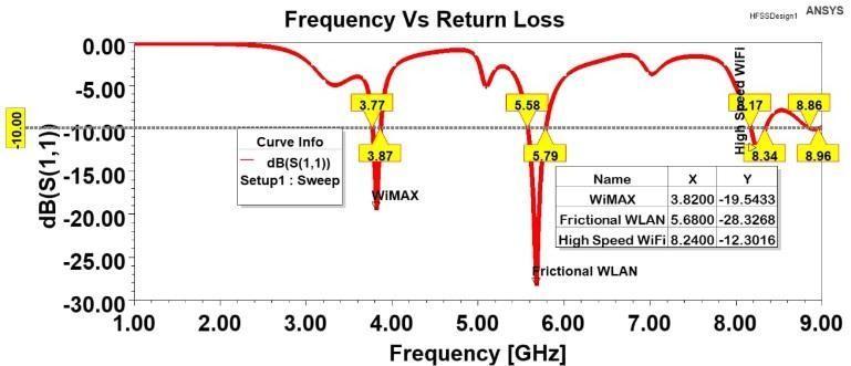
Inthispaper,adiamond-shapedmicro-strippatchantennais created using fractal patterns. Industries include factories, the study of conductors, and the realm of medicine, where antenna were frequently utilised for imaging purposes. Different feeding techniques, including micro-strip feeding, insetfeeding, and coaxial feeding, are used to simulate and compare the proposed antennas. Comparing these three feedingmethods, theinsetfeedingantennafeedsbetterthan otherfeedingmethods.Thecreatedantennaissmallinsizeof 20L*1.6W*20Hwith FR4substrate.Avarietyoffactors,such safeguarding patients, miniaturisation, biological compatibility, minimal power and energy consumption, limitedfrequencies in functioning, as performance must all be taken into attention to allow the implants antenna to function more reliably and constantly. The glass- reinforced epoxy laminate material FR-4 with a dielectric constant of 4.4 has been selected as the dielectric material for this method. In the design of implantable sensors, choosing the antennaisadifficultproblembecauseitaffectshowwellthe entire implant performs. For implantable medical applications, we can choose Rogers5880 substrate. For the entire operational frequency range, the DS- MPA has a Voltage Standing Wave Ratio (VSWR) of 1.64 and a Return Loss (RL)of -23.01dB.HFSS isusedtodesignandmodelthe antenna andachieves good output response. It resonates at frequencyrangesof3.8,5.6and8.2GHz.
Keywords: Industrial, Scientific, and Medical (ISM), Biomedical applications, FR-4, VSWR, Return Loss,5G applications.

1. INTRODUCTION:
Today, different types and shapes of antenna are being developedusingdifferentsubstratematerials. Anantennais an electric device which convertselectric energy into radio waves and vice versa. It is being used for radiating and receiving the radio waves. Micro-strip antenna plays a vital role in Wireless communication. MSA is a radio antenna which is small, less weight, and easy for manufacturing.
Many industries needed a compact, miniaturized and affordable wireless devices. Micros trip antennas are developed using different substratematerials and different geometries based on the operating frequency.[10]There are various frequency bands for biomedical applications, includingISM(Industrial,Scientific,andMedical),whichhasa 2.4 GHz frequency band, MICS (Medical Implantable Communication Service), and Med Rad (MedicalDevice Radio band), whose frequency range is 401- 457 MHz. Popular in biomedicine is the implanted antenna, which can pick up bio-signals and sendthem to an outside device. It is used in medicine, healthcare, and the treatment of cancer. Both thedoctorandthepatientcanbenefitfromtheabilitytoselfmonitor.Thehumanbodycontainsimplantableantennasthat are used to monitor things like temperature,bloodpressure, andsugarlevels.Fractaldesignsareusedtocreateadiamondshaped micro- strip patch antenna. For more effective analysis, fractal structure was used.[14]The term "fractal" describes a wide range of extremely asymmetrical curves or patterns that are reproducible at all scales. The functionality ofthetraditionalantennasisimprovedbytheemploymentof fractal structures. The fractal structures are derived using a variety of shapes, including square, rectangle, triangle, trapezoid, circle and oval. The proposed micros trip antenna ismadebycuttingarhombuswithasidelengthof4mmtoget the diamond-shaped micros tripantenna. Tuning stubs are also employed in conjunction with the structures to enable broadband operation. The antenna's performance is influenced by the substrate's thickness, permittivity, and material.[2]
2. LITERATURE REVIEW:
In order to minimize the size of the radiation structure, a triangular MPA is created for automotive applications. In vehicular communications, it can beused to identify blind spot detection. With a 79% compactness, the proposed structure operates at a frequency of 5.88 GHz. The authors of this researchhave designed a rectangular MPA for usewithWi-Fi.[5]Tomakethephysicalstructuresmaller,self symmetry fractal patterns are used. The Sierpinski carpet fractal shapes are added to the ground portionof the MPA to
create the DGS. It causes the antennato operate in the 2.4 GHz frequency band and resultsin a size reduction of up to 32.9%.
The modified Koch-fractal structures in the ground portionoftheMPAareusedbytheauthors ofthistechnique to achieve the desired miniaturization. The suggested design results in animproved BW and a practical reduction in physicalsizeofupto20.35%.[1]
The authors propose a compact fractal MPA for Long Term Evolution (LTE) application. The coplanar waveguide feedisincludedtominimizethedesign'sphysicaldimensions and enhance BW.[4] The fractal patch's dimensions were changedtoprovideanRLof-23.45dB,aVSWRof1.14,anda BWof375MHz
TheauthorsofthisstrategysuggestedanMPAdesignfor communications with multiple functions. The ground is dividedintoH,L,andU-shapedslotsintheminiaturedesign. The proposed structure is considerably smaller than the usual one as a result ofthe use of fractal structure. [8]The response range ofthe suggested antenna is from 1 GHz to 8 GHz.Thestructure'sgain ranges from2.1 to 3.87 dB,and its directivityisbetween4.3and5.3dB.
The authors proposed a coaxially fed, circularMPA. Thisantennaismadetoemitatafrequencyof
5.12 GHz. This antenna's design and verificationwere done in the HFSS simulator. The working frequency of the proposed structure, which ranges from 5.17 to 5.32 GHz, is guaranteed to resonate at
5.248 GHz. RT/duroid with a constant of 2 was usedas the substrate material for this antenna. An antenna's key performanceindicatorsareevaluatedandconfirmed. [11]
The fractal structure on a 5.2 GHz rectangularMPA patchsectionwasproposedbythecreatorsofthissuggested antenna.Theantennaworksinseveralfrequency bands as a result of the fractal construction. The best RL, gain, and VSWR are achieved in the corresponding frequency bands. The HFSS simulator is utilized to design and verify the proposed antenna, and FR-4 has been selected as its dielectricmedium.[12]
λ/4 impedance converter has been added to the designforthebestimpedancematching.Theperformanceof the suggested structure has undergone several iterations, fromwhichthesecondoneisconstructedandevaluated.The additionof fractaldesignresults inasizedecreaseof43.7% when compared to the traditional one. The antenna's
operatingfrequencyis2.14GHz,andtheRLatthat frequency hasbeenmeasuredtobe-24dB.[13]
3.FRACTAL GEOMETRY ANTENNA:
Fractals were first defined by Benoit Mandelbrot in 1975 as a means of classifying structuresof non-integer size. Fractalgeometryisa verygoodsolutiontoreducethesizeof the antenna.Fractalantennashaveinterestingfeaturesdueto their geometry.[3]Antennas with intriguing features like multi-band operation and miniaturization can be realized because of the special traits of fractals including selfsimilarityandspace-fillingproperties.
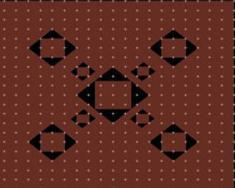
4. DESIGN OF DIAMOND SHAPED MICRO STRIP FRACTAL ANTENNA:
The suggested antenna was created and testedusing theHighFrequencyStructureSimulator(HFSS).Thedielectric material FR-4 with a width of 1.6 mm was chosen for the proposed DS-MPA design. The proposed DS-MPA's fundamentaldesignis a 20 mm long, ground-mounted patch. 20Becauseof the unique characteristics of fractals, including asself-similarity and space-filling qualities, it is possible to create antennas with exciting features like multi-band operation and miniaturization. It uses the transmission feeding technique. Every iteration usesthe same 10 mm feed length and placement. The suggested antenna uses iterative approaches that were calculated through a computer or mathematicalprocedure.[15]TheDS-MPAdesigniscreatedby cutting a rhombus with a side length of 4 mm in orderto achievetheproposedantennaminiaturizationinthiscase.
Thesquaregeometrycanbestretchedtocreateafractal structureinthemiddlesquarefractalslot,whichreducesthe size of the structure. Use an iterative process with a 10 mm feed length and the same feed position for all iterations. Iteration uses frequencies between 2GHz and 8GHz. This paper's maincontribution isthedesignofa diamond fractal antenna for improved performance in terms of size reduction and return loss measurements.[6]Thesecond way results in the antenna structure's compactness, which is a crucial quality for the biological application. These fractal groovesmeasure4mm,2mm,and1mmoneitherside.The geometry of the fourth iteration, which has square fractals withlengthsof1mm,isarhombuswithsidesof 4 mm each. Theproposedantennauses45%less spacethanthecurrent design while maintaining the same resonant frequency. Therefore, it is claimed that at 5.9 GHz, the size of the proposed antenna design has effectively been reduced to 45%.Lowdielectricconstantandanincreaseinthefringing field at the patch periphery are caused by a thick substrate, whichalsoincreasestheradiatedpower.[16]
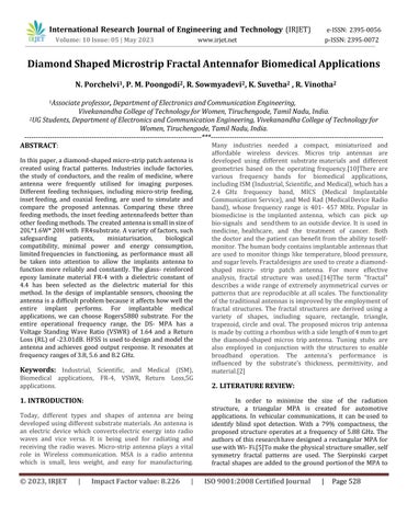
5. DESIGN FLOW:
6. ITERATION PROCESS:
Theiterationmethodcallsforrepeatedlyperformingastepa predeterminednumberoftimes.Thesquare-cuttingprocess is repeated to produce the suggested antenna design.Four iterations were carriedoutfor this project in orderto boost theantennaparameters.

1. First iteration: Cutting square geometry with4mmlongsidesinthecenterofthesquarepatch,asshowninfig.1, yieldsadiamond-shapedfractalantenna.VSWRof1.067and returnlossof-33.97dB.

2. Second iteration: The outcomes of the second iteration of the suggested fractal antenna are shown in Figure 2. One square fractal slot with squaregeometry, each with a side length of 4 mm, is taken in the center, and four additional slots,eachwithasidelengthof2mm,aretakenoneachofthe four corners of the central slot. At the resonant frequency,a VSWRof1.04andareturnlossof-34.01areavailable.

 Fig1.1:Iteration1
Fig1.2:Iteration2
Fig1.3:Iteration3
Fig1.1:Iteration1
Fig1.2:Iteration2
Fig1.3:Iteration3
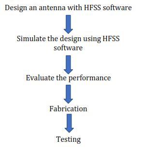
3. Third iteration: Inthissinglecentersquarefractalslot, square geometry is deployed, and smaller versions of the samestructuredfractalaretakenoneachofthefourcorners ofthecentral slot.These fractal slots,whicharedepictedin figure 3, have dimensions of L1=4mm, L2=2mm, and L3=1mmoneachside.
4. Fourth iteration: In the fourth iteration, a diamondshaped fractal with equal sides and a 1 mmdimension is used in a rhombus geometry with4 mm-long sides on each side. There are fouridentical slotswitha 2mmlength in each corner away from the center. For the specified resonant frequency, a VSWR of 1.64 and a reflection attenuation of -23.01 are achieved in this instance. The square geometry can be stretched to obtain a fractal structurein the centersquare fractal slot,whichresultsina smaller structure.[9]These fractal grooves are 4mm, 2mm, and1mmwideonbothsides.


Hence, it is stated that the size of the proposed antenna design has been effectively reduced to 45% at 5.9 GHz.When compared to the existing design, the proposed antenna consumes 45%less area with the same resonant frequency.Thefrequencyrangeusedforiterationis2GHzto 8GHz.The return loss is increased from -20.89 dB to 29.79 dB, radiation efficiency is improved from 97.66% to 100%, and compactness of 9.83% is gained over the conventional antenna by inserting a diamond-shaped slot with ideal geometries at a suitable place. As a result, it is claimed that the DS- MPA design's size has been efficiently decreased to 45%at5.9GHz.[7]
The developed biomedical implantable patch antenna is tested in space and constructed on a Roger RT5880substratewitha0.254mmthickness.Theimplanted antenna's S11 is measured using a vector networkanalyzer (VNA).In the case of the simulated results, the planned antenna covers the bandwidths from800MHzto1000MHz (200 MHz) at 915 MHz, however in the case of the measurements,theantennacoversthebandwidthsfrom795 MHzto998MHz(203MHz)at915MHz.
The suggested DS-MPA's performanceresults have been evaluated using factors like VSWR, Gain, reflection attenuation, and operating frequency. This suggested antenna was constructed, tested, and figures a and b serve as proof of the gainand 3D gain plot of the DS-MPA design for values ranging from 0° to 180° and -200° to 200°, respectively.
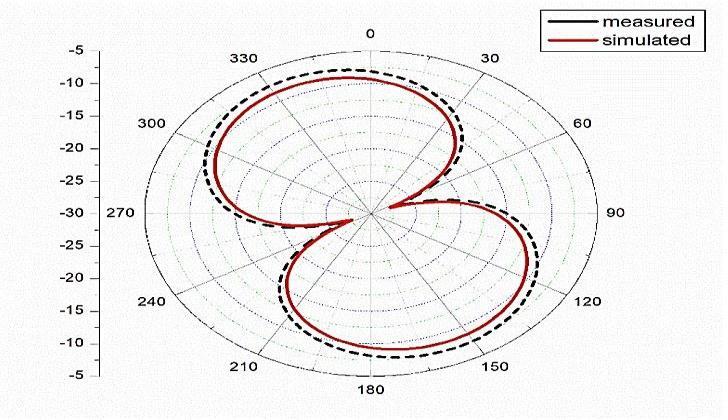
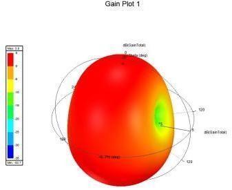
The Gain is increased to 5dB in this instance, demonstratingthattheDS-MPAprovidesthebestGain.The measuredGainof4.3dBisshowninFigurea.
The gain in a particular direction is described in termsofdB,andthisfront-to-backratioisusedto compare such gains. The front-to-back ratio of the proposed structure's mode 1 DS-MPA is plotted in
3.50dBatafrequencyof3.82GHz.At3.28GHz, theratioin mode2isdepictedat5.68dBofidealgain.
Gain of 4.3 dB is displayed in Figure a. TheVSWR oftheDSMPUantennais showninFigureC.Eachbandhas a permissible VSWR value,which ranges from 1.23 for 3.82 GHz to 1.07 for
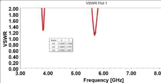
5.68 GHz to 1.64 for 8.24 GHz. The DS-MPU's output has a value close to 1, which verifies that the whole input signal isintendedtoberadiatedwithverylittlereflection.
8. CONCLUSION:
The fractal structure can minimize the patch size without impacting the antenna performance, such as reflection attenuation, radiation pattern, or VSWR, accordingtotheresultsofthesuggestedDS-MPA. The SAR values arefoundtobe8.1W/kg insidetheskin.TheVSWR, RL,andGainvaluesforthe DS-MPA are 1.65, -23.01, 3.51, and 3.87, 5.2,
5.8, and 6.9 GHz, respectively. The antenna performance was investigated with body and withoutbody: the results show negligible deterioration. The various design stages demonstrate the increases in bandwidth and reflection coefficient. The iterations I, II, III, and IV unmistakably demonstrate how the self likeness and symmetry modify thereflectionattenuation.Thisantennaisminiaturizedand anidealapplicantforin-bodybiomedicalapplication.
REFERENCE:
[1] I Masroor, J. A. Ansari and M. Kumar, "High EfficiencyFractalCircularMicrostripPatchAntenna(CMPA) with Circular Defected Ground Plane for 5 GHz WLAN Applications," in 2020 IEEE 7th Uttar Pradesh Section International Conference on Electrical, Electronics and Computer Engineering (UPCON), pp.1–5,doi: 10.1109/UPCON50219.2020.9376466
Fig4:ThegainofDS-MPAantennaInternational Research Journal of Engineering and Technology (IRJET) e-ISSN:2395-0056
Volume: 10 Issue: 05 | May 2023 www.irjet.net
[2] 2020 National Conference on Emerging Trends on Sustainable Technology and Engineering Applications (NCETSTEA), pp. 1-3, doi:10.1109/NCETSTEA48365.2020.9119949 T.Mondal, S. Suman, and S. Singh, "Novel Design ofFern Fractal Based TriangularPatchAntenna,"
[3] ISurjati,Y.K.NingsihandS.Alam,"Compactfractal patch microstrip antenna fed by coplanar waveguide for long term evolution communications," 2017 4th International Conference on Electrical Engineering, Computer Science andInformatics (EECSI), 2017, pp. 1-4, doi:10.1109/EECSI.2017.8239180
[4] M. eMunir, A. Altaf and M. Hasnain, "MiniaturizationofmicrostripfractalH-Shapepatchantenna using stack configuration for wirelessapplications," 2015 IEEE 2nd InternationalConference on Recent Trends in Information Systems (ReTIS), 2015, pp. 44-48, doi: 10.1109/ReTIS.2015.7232850.
[5] R. V. H. Prasad, D. Vakula and M.Chakravarthy,"A Novel Fractal Slot DGS Microstrip Antenna for Wi-Fi Application,"2018IEEEIndianConference on Antennas and Propogation (InCAP), 2018, pp. 1-4, doi: 10.1109/INCAP.2018.8770773.
[6] N. Gurgel, I. Queiroz, H. Andrade and T. Silveira, "Miniaturization of microstrip patch antennas using Koch fractal geometry on the groundplane," 2021 SBMO/IEEE MTT - S International Microwave and Optoelectronics Conference (IMOC), 2021, pp, 1-3,doi: 10.1109/IMOC53012.2021.9624798.
[7] Mark C Shults, Rathbun K Rhodes, Stuart J Updike, Barbara J Gilligan, and William N Reining. A telemetryinstrumentation system for monitoring multiple subcutaneously implanted glucose sensors. IEEE Transactions on Biomedical Engineering, 41(10):937–942, 1994
[8] Mohsen Zaeimbashi, Hwaider Lin, Cunzheng Dong, XianfengLiang,MehdiNasrollahpour,HuaihaoChen,Neville Sun, Alexei Matyushov, Yifan He, Xinjun Wang, et al. Nanoneurorfid: A wireless implantable device based on magnetoelectric antennas. IEEE Journal of Electromagnetics, RF and Microwaves in Medicine and Biology, 3(3):206– 215, 2019.
[9] K. S. Patil, and E. Rufus, "Microwave Antennas SuggestedforBiomedicalImplantation",inAntennaSystems [Working Title]. London, United Kingdom: IntechOpen, 2022.
p-ISSN:2395-0072
[10]S.Ashok Kumar,M. Arun Raj,T. Shanmuganantham, Analysis and design of CPW fed antennaatISM bandfor biomedical applications, Alexandria Engineering Journal, Volume 57,Issue2,2018.Page723727,ISSN11100168,http s://doi.org/10.1016/j.aej.2017.02.008
[11] S. Sarjoghian, M. H. Sagor, Y. Alfadhl and X. Chen, "A 3D-Printed High-Dielectric Filled Elliptical DoubleRidged Horn Antenna for Biomedical Monitoring Applications," in IEEE Access, vol. 7, pp. 94977-94985, 2019,doi:10.1109/ACCESS.2019.2928629.
[12]Ayesha Ahmed, Tahera Kalsoom, Masood UrRehman, Naeem Ramzan, Sajjad Karim, and Qammer H. Abbasi. Design and study of a small implantable antenna design for blood glucose monitoring. ACES Journal,33(10), October2018.
[13] N. Ganeshwaran, J. K. Jeyaprakash, M. G. N.Alsath, and V. Sathyanarayanan, “Design of a dual- band circular implantable antenna for biomedical applications,” IEEE Antennas and Wireless Propagation Letters, vol. 19, no. 1, pp.119–123,2020.
[14] S. Shekhawat, S. V. Gunaram, and D. Bhatnagar, “CPW fed implantable elliptical patch antenna for biomedical application,” AIP Conference Proceedings, vol. 2220,article130068,2020.
[15] D. Nguyen and C. Seo, “An ultra- miniaturized antenna using loading circuit method for medical implant applications,” IEEE Access,vol.9,pp.111890–111898,2021.
[16] K. Zhang, C. Liu, X. Liu, H. Guo, and X. Yang, “Miniaturized circularly polarizedimplantable antenna for ISM-band biomedical devices,” International Journal of Antennas and Propagation,vol.2017,9pages,2017.