Optimization of powertrain of jib crane
Aditya Gokhale1 , Dheeraj Bangar2 , Prof. Prasad Bhide31BE in mechanical engineering PVG’s College Of Engineering and Technology, Pune , Maharashtra, India
2BE in mechanical engineering PVG’s College Of Engineering and Technology, Pune , Maharashtra, India
3Assistant Professor, Dept.Mechanical Engineering of PVG’s College of Engineering and technology, Pune, Maharashtra, India ***
Abstract - To optimize the power transmission system for the slewing motion of a jib crane, including the gear, pinion, and geared motor, for all coordinates of the lifted load from the pillar center, the entire system needs to be carefully analyzed and refined. This involves selecting suitable gears, pinions, and a geared motor that can handle the load requirements and desired range of motion. The design should consider factors like torque, speed, efficiency, and safety. it is necessary to perform a comprehensive analysis and implement topology optimization techniques for the ring gear.
A boom of jib crane experiences a maximum load when the load is acting at the maximum span / Outreach of the crane from pillar centre. Hence the motor and gearbox for jib crane is designed according to the beam under maximum possible loading condition.However, the actual movement of load happens at various coordinates from centre of the pillar which is different from the maximum value. The aim of this project is optimization of complete power transmission for slewing motion of jib crane which includes the gear, Pinion, and Geared Motor for all coordinates of the lifted load from pillar centre.
Key words: jib crane , ring gear , Optimization
1. INTRODUCTION
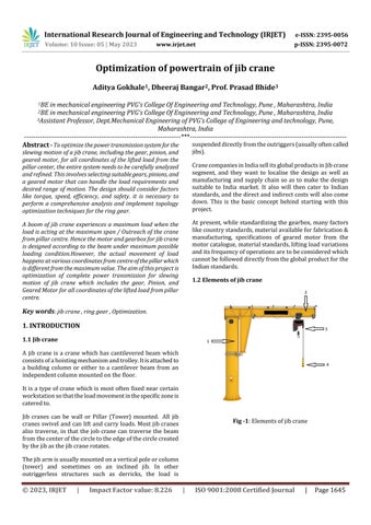
1.1 Jib crane
A jib crane is a crane which has cantilevered beam which consistsofahoistingmechanismandtrolley.Itisattachedto a building column or either to a cantilever beam from an independentcolumnmountedonthefloor.
Itisa typeofcranewhichis mostoftenfixednearcertain workstationsothattheloadmovementinthespecificzoneis cateredto.

Jib cranes can be wall or Pillar (Tower) mounted. All jib cranes swivel andcanliftandcarry loads. Most jibcranes also traverse, in that the job crane can traverse the beam fromthecenterofthecircletotheedgeofthecirclecreated bythejibasthejibcranerotates.
Thejibarmisusuallymountedonaverticalpoleorcolumn (tower) and sometimes on an inclined jib. In other outriggerless structures such as derricks, the load is
suspendeddirectlyfromtheoutriggers(usuallyoftencalled jibs).
CranecompaniesinIndiasellitsglobalproductsinJibcrane segment, and they want to localise the design as well as manufacturing and supply chain so as to make the design suitable to India market. It also will then cater to Indian standards,andthedirectandindirectcostswillalsocome down. This is the basic concept behind starting with this project.
Atpresent, while standardizingthegearbox, many factors likecountrystandards,materialavailableforfabrication& manufacturing, specifications of geared motor from the motorcatalogue,materialstandards,liftingloadvariations anditsfrequencyofoperationsaretobeconsideredwhich cannotbefolloweddirectlyfromtheglobalproductforthe Indianstandards.
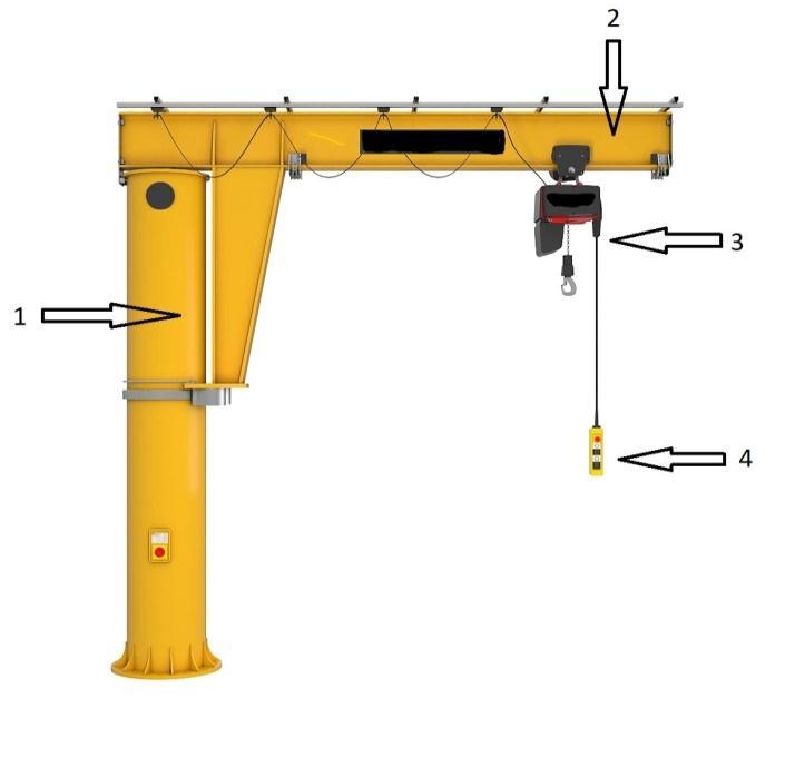
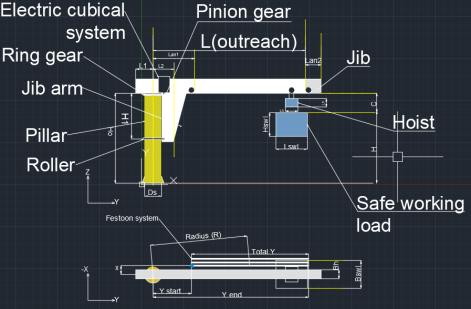
Elementsofgearbox
1) Pillar: Vertical Member of jib crane which support the completeJib
2)JibArm:HorizontalmemberonwhichtheHoisttravel. Hoist:Liftingmachinewhichliftstheload.Ithas2motions a)Lifting/Lowering,b)Travelling.
3) Pendant: It is one of the devices which gives control signals to the jib crane, other devices are Radio remote, Joysticketc…
4)Pinion:ItengageswiththeGearringwhichrevolvesand rotatesgivingslewingmotiontotheJibarm.
5)GearRing:TheGearisfixedtopillarandpinionrevolve aroundthegeartogiveslewingmotiontojibarm.
6) Slip Ring assembly: Slip Ring assembly is needed to deliverthepowersupplytotheothermachineriesasthejib cranesrotates360degrees.
7)FestoonSystem: System deliveringpowertothehoist basedCtrackandpowersupplytrolleys.
1.2 Calculations
Table -1 Terminologiesandabbreviations
Term Lan1 JibSlewing rpmn Hook approach _Outer
load(SWL) Lan2 Safe Working Load(SWL) dimensionsBeam Overhangon rearside
L1 Length Lswl Positionof Arm L2 Width Bswl ArmHeight H1 Height Hswl Diameterof Pillar Ds Height Hswl Hookpath abovefloor H HoistHead Room C Floorto bottomof beam
Ho=H+C Hoistweight Gh
Totalcycles-25000
Jibrpm=1
Totalduration=25000min
Totaldurationinh=4166.67
2. Types of loads acting on jib crane-
1.UniformlyDistributedLoad(UDL)(Festoonsystem)
2.PointLoad
3.LiveLoad
2.1.Calculations for UDL (festoon system) -
∴Radius=
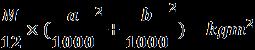
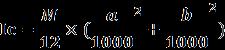
∴Ic=
Io=Ic+
Momentaroundpillar=
2.3 Calculations for live load
Iteration 1-
Totalload=M=SWL+Hoistload
Radius=R1 m
Icswl=
UDL=
lengthofUDL=
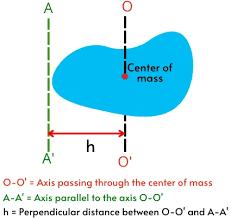
Fig -3:MOIexplaination
WidthofUDL=bm
∴Pointload=
HorizontaldistanceofCGofudl=x
VerticaldistanceofCGofudl=y
DistanceofCGofUDLfrompillar
Ic=MMIofUDLaroundCG=
Io=
Momentaboutpillar=
2.2 Calculations for point load & fixed crane loads-
Load=mkg
∴Totalload=M=m*Massfactor
Lengthofload=am
Widthofload=bm
Diatanceofxcoordinate=x
Distanceofycoordinate=y
Ichoist=
∴Io1=
∴Momentaroundpillar=M1=
Iteration 2-
R2
∴Corresponding Io2=Icswl+Ichoist+
∴Momentaroundpillar=M2=
Iteration 3-
R3
∴Corresponding Io3=Icswl+Ichoist+
∴Momentaroundpillar=M3=
Andsoonforfurtheriterations
∴Max.Io=
∴RMSIo=
Max.Moment
=
∴RMSmoment=
∴TotalMMI=
∴Totalaxialforce=
∴TotalMomentaroundpillar=
Armheight=H1m
∴Radialforce=
Totalaccelerationtorque=
Frictionalforce=
∴Frictionaltorque= Axialtorque=
∴Totaltorque=Frictionaltorque+axialtorque+ accelerationtorque Nm
Setmotorrpm=
Totalratio= ∴
∴power=
Totalefficiency=
∴Finalmotorpower= kW
Optimization of power of motor
2. HEADING 2
Using maximummethod-
UDL (Uniformly Distributed Load)Festoon 1
UDL=5kg/m
WidthofUDL=50mm=0.05m=b
UDLstart(Ystart)=200mm
UDLend(Yend)=6000mm
TotalY= =6000-200 =5800mm =5.8m =a
CGofY= =3100mm =Ycoordinate
Distanceoffestoon1fromjibarm =500mm =Xcoordinate
(x,y)=(500,3100)
∴Radius= =3140.1mm R =3.14m
∴Totalload= = = =29kg
Massfactor(M.F.)=1.1
∴LoadwithM.F=
∴M=31.9kg
∴MR^2= = 314.5kgm^2
∴Self MR^2= Ic =MMIaboutCGoffestoon1 =
Ic=89.4kgm^2
∴MMI about pillar= =89.4+314.5 =404kgm^2
∴Moment about Pillar = =970.1Nm
Festoon 2Forfestoon2, Distanceoffestoon1fromjibarm =750mm =Xcoordinate
(x,y)=(750,3100)
∴Radius=3189.4mm M=31.9kg
∴MR^2= 31.9*3.189^2 = 324.5kgm^2
∴Self MR^2 =Ic= MMIaboutCGoffestoon2 =
=89.4kgm^2
∴MMI about pillar = Io =413.9kgm^2
∴Moment about Pillar = =970.1Nm
Live load-
Iteration 1
Max. outreach= 6000 mm
Max. Load = 5000 kg
Hoistload=600kg
∴Totalload=5600kg
Iteration1SWL=5000kg
HoistLoad=6000kg
TotalLoad=SWL+Hoistload M =5600kg
DistanceofSWL& Hoistloadfrompillar= Max.ofoutreach/2&positionofarm
=max
=max =3000mm =R1
∴MR^2= = =50400kgm^2
∴SelfMR^2ofSWL=Ic1= = =1068.58kgm^2
∴SelfMR^2ofhoist=Lc2= = =12.25kgm^2
∴TotalMR^2aroundthepillar =Io =MR^2+Ic1+Ic2 =50400+1068.58+12.25 =51480.8kgm^2
Momentaroundjibarm = = =164808Nm
Iteration 2SelfMR^2ofSWL=Ic1
=1068.58kgm^2
∴SelfMR^2ofhoist=Lc2 =12.25kgm^2
R2= =3750mm =3.75m
∴MR^2= =78750kgm^2
∴TotalMR^2= MR^2+Ic1+Ic2 =78750+1068.58+12.25 =79830.8kgm^2
∴Moment = =206010Nm
Iteration3-
SelfMR^2ofSWL=Ic1 =1068.58kgm^2
∴SelfMR^2ofhoist=Lc2 =12.25kgm^2
R3= =4500mm =4.5m
∴MR^2= =113400kgm^2
∴TotalMR^2=MR^2+Ic1+Ic2 =113400+ 1068.58+12.25 =114480.8kgm^2
∴Moment= = =247212Nm
Iteration 4-
SelfMR^2ofSWL=Ic1 =1068.58kgm^2
∴SelfMR^2ofhoist=Lc2
=12.25kgm^2
R4= =5250mm =5.25m
∴MR^2= =154350kgm^2
∴TotalMR^2=MR^2+Ic1+Ic2 =154350+ 1068.58+12.25 =155430kgm^2
∴Moment= =288414Nm
Iteration 5SelfMR^2ofSWL=Ic1 =1068.58kgm^2
∴SelfMR^2ofhoist=Lc2 =12.25kgm^2
R5= =6000mm =6m
∴MR^2= =
=202680
∴Moment =329616Nm
SimilarlywecanfindMax.andRMSIoandMMI&comparetogrther
%DecreaseinpowerformaximumLoad&outreachconditions-
%Decreaseinpower(kW)=
Conclusion- For each iteration of load vs outreach data, Root Mean Square method power is coming to be minimum for correspondingiterationformaximummethod.
Thus,powerrequiredtorotatethejibisreducedby28.41%
Validation using Tooth root stress -
Knowndata–
Module=m=6
Pressureangle=20deg
Helixangle=0deg
Piniongear=gear1
Ringgear=gear2
∴
V1
Tangentialforcetransmitted=Wt1
Velocityfactor
Kv1
Permissiblestress
BHN
Infinitelifestrengthfortoothrootstress
Syt
Factorofsafety=
∴BalancedFOS
∴Transmittablepower=
∴Calculationaccuracy
Validation using flank strength -
Contactstrength=Sc=
CL=LifeFactor
CH=Hardnessfactor
CT=TemperatureFactor
CR=ReliabilityFactor
AGMAstressratio=
∴Dynamicfactor=Kv1=
∴Safetyfactor=
∴Geometricalfactor=
∴Weightforcetransmitted=Wtf=
∴Safetyfactor=
∴Transmittablepower=
∴Calculationaccuracy
3. CONCLUSIONS
The accuracy coming from method of tooth root stress is around85%forgear1(pinion)whileforsomegearofisof 115%
Whileusingflankstrengthmethodtheaccuracyforgear1is comingtobe81%andforgear2itisaround150%.
Ingeneralvalidationunsungtoothrootstressisconsiderable andcanbeusedforoptimizationofringgear.
REFERENCES
[1]KrunalGandhare,VinayThute,“DesignOptimizationofJib Crane Boom Using Evolutionary Algorithm”, International Journal of Scientific Engineering and Research, Volume 3 Issue4,pp.2-8,2014.

[2]BakerJ.CranesinNeedofChange,Engineering,Vol.211, PP-298,1971.
[3]SandipD.Shinde“StandardizationofJibCraneDesignby “F.E.M. Rules” and Parametric Modeling”, International Journal of Recent Trends in Engineering, Vol. 1, No. 5, pp. 145-149,May2009.
[4] K. Suresh Bollimpelli, V. Ravi Kumar, “Design and Analysis of Column Mounted JIB Crane”, International Journal of Research in Aeronautical and Mechanical Engineering,Vol3issue1,pp.32-52,2015.
[5]AmreetaR.K.“DesignandStressAnalysisofSingleGirder JibCrane”,InternationalJournalofEngineeringResearch& TechnologyVol.4Issue09,pp.932-936,September-2015.
[6]SubhashN.Khetre,S.P.Chaphalkar“ModellingandStress Analysis of Column Bracket For Rotary Jib Crane”, international journal of mechanical engineering and technology Volume 5, Issue 11, pp. 130-139, November 2014.

[7]Gerdemeli.I,Kurt.SandTasdemir“DesignandAnalysis with Finite Element Method of Jib Crane”, Mechanical EngineeringIstanbulTechnicalUniversity–Turkey2012.
[8]B.Ünal,I.Gerdemeli, C. E.Imrak “ModellingandStatic Stress Analysis of Shipyard Jib Crane With Finite Element Method”,UniversityReviewVol.2,No.4Trenčín:Alexander DubčekUniversityofTrenčín2,90p,2008.
[9] Fuad Hadžikadunić, NedeljkoVukojević and SenadHuseinović “An Analysis of Jib Crane Constructive Solution in Exploatation”, 12th International Research/ExpertConferenceTrendsintheDevelopmentof MachineryandAssociatedTechnology''TMT2008,Istanbul, Turkey,pp.26–30August,2008
10)Shigley'sMechanicalEngineeringDesignBookbyJ.Keith NisbethandRichardG.Budyna
BIOGRAPHIES
AdityaAnantGokhaleiscurrently pursuingBachelorofEngineering degree in mechanicalengineering program in Pune Vidhyarthi Griha'sCollegeofEngineeringand Technology.
Dheeraj Bharat. Bangar is currently pursuing Bachelor of Engineering degree in mechanicalengineering program inPuneVidhyarthiGriha'sCollege ofEngineeringandTechnology.
Prof. Bhide Prasad Pramod Assistant Professor3 Assistant Professor, Dept Mechanical Engineering of PVG’s College of Engineering and technology, Pune,Maharashtra,India