
Analyzing the role of Segmental lining in the tunnels with Tunnel Boring Machine (TBM) at Vishnugad Pipalkoti Hydroelectric project (4*111
MW). A case study
Prashant Sharma1 , Monu Rajpoot, Saurabh Soni3
¹ M. Tech Transportation Engineering, IIMT University Meerut (U.P.)
2Associate professor, Civil department, IIMT University Meerut (U.P.)

3 Professor, Civil department, IIMT University Meerut (U.P.)
*** -
Abstract -Segmental Lining in tunnels have the potential to play a significant role in managing & providing sufficient strength to the tunnels rather than time consuming concrete lining. The segmental lining or lining with precast segments is very fast process as various segments which are pre-constructed or pre-casted with required grade of concrete & reinforcement, categorized as per rocks classification and geological conditions of the tunnels gets installed with automatic Tunnel Boring Machine (TBM). The process of installation is a continuous process i.e., just needed pre-casted segments to install. Since direct cost of project is associated with time and hence studies and research are made to minimize the cost of construction and reducing project duration. Concrete lining has proved to be a time-consuming process since involvement of various necessary preparations viz. placing of reinforcement followed by shuttering that after concrete of necessary grade according to the design mix needs to be feed and ultimately curing. Construction of the project gets delayed therefore to avoid such issues concrete lining is now days replaced by the Segmental lining as this practice having various advantages when compared with Concrete lining. (Segmental method also have a better aesthetic view than lining since it can’t be uniform)
Key Words: Concrete segments, Segmental Lining, Tunnel Boring Machine (TBM), Concrete Lining, rocks classification, rock formation, headrace tunnel, shear zone.
1. INTRODUCTION
Theprojectarea ofVishnugadPipalkotiHydroelectricprojectislocatedatnorthern India intheprovinceUttarakhandat AlaknandaRiver.Thehydropowerplantiscontaininga reservoirbesidetheriverwithintakeanddesilter`,theheadrace tunnel,surgeshaft,undergroundpowerhouseaswellasthetailracetunnel.Theelectricpoweroftheplantisgivenwith4 x111MW.Thereportathandisfocusingatthesegmentalliningoftheheadracetunnel,describingthegeometricaldesign ofthesegmentallininganditserectingstructuralanalysis.
Salient features of VPHEP
Dam/ water level at dams: TypeConcreteGravityDam,Length 89.55m.,Height65m.,TopEl-1270m.,FoundationEl1205,FRL-1267m.
Headracetunnel: Length13.4Km,Dia 8.8m (finish),Designflow:228.86m³/sandcircularshaped
SurgeShaft RestrictedOrificeType,Dia.15m./22m.,Height140m.
Pressureshaft Nos02/04,TypeCircular,Dia 5.2m/3.65Length310m/35m
Powerhouse TypeU/G,Size146x20.3x50,Unit04nos.(each111MW),Turbinetypes:Francis
Surgetank TypeU/G,Size150x16x35,Max.SurgeLevel1040m,Min.1026.5m
Tailracetunnel Size8.8m dia (Horseshoeshaped),Length3070m.
Planview
1.1 Case study-Geology
(Pipalkoti and Gulabkoti formations are present along the headrace tunnel. Both rock formations are composed of Dolomitic Limestone, Slates, Amphibolite, Quartzite and shear zones the percentage of Dolomitic Limestone is given with 38.25% while Slates are present with 56.56%. The amount of shear zones is given with 3.11%. Amphibolite is proposed withapercentageof0.74%whileQuartziteispredictedfor1.34%ofthetotallength.),theuseofsegmentshasthepotential togreatlyimprovetheefficiencyandsustainabilityoftunnel.

1.2 Plan view
Theheadrace tunnel of VishnugadPipalkotiH.EProject will be excavated bydrill andblastmethod aswell asbyTBM (Tunnel Boring Method). Tunnel alignment is composed of the following geometric elements the total length of the headracetunnelis13’430.37m,where12kmareexcavatedbyTBMandlinedwithsegmentallining.Thecurrentreportis only focusing on the approximately 12.0km long head race tunnel excavated by TBM. This tunnel stretch will be designatedfurtherasVishnugadHRT.
1.3 Lining Segment’s dimensions
IrjetThefollowingsalientfeatureshavebeendefinedtoserveasabasiswithintheliningdesign
-Internaltunneldiameter:Di=8’800mm(asperrequirement)

-Segmentthickness:st=350mm
-Excavationdiameter:Dexc=9’860mm

-Segmentwidth(nominal):sw=1’500mm
-Annulargap(nominally):a:=180mm(geometricallyderived)
-Segmentsystem:left/rightringsystem
1.4 Methodology- Facilities for TBM operation
In order to start actual excavation of HRT by TBM there are various initial facilities are to be developed which supportsvariousfunctionssuchactivitiesarelistedbelow.
DevelopmentofTBMPlatformforassemblyofTBM
DevelopmentofCasting&InitialcuringYard
Developmentofnormalcuringyard
Developmentandinstallationofhigh-capacitypowerPlant
InstallationofAssemblysupportequipment’s.
1.5 Ring Installation
For assembling of the segment ring, the invert segment will be installed first, being put on the dowels of the circumferentialjointandrestingontheinvertpads,butinadditionbeingheldinpositionbymeansoftheauxiliarythrust cylindersoftheTBM.Withinthenextstepsthebothleftandrightbottomandtopsidewallsegmentswillbeinstalledand kept in position by means of the auxiliary thrust cylinders. As last element of the ring, the key segment will be placed in positionbymeansoftheauxiliarythrustcylinders.Nowthecompleteringisassembled.
Dowel connectors (three for each segment) have the function to facilitate the proper placement of the concrete segment duringtheringassemblyandtoguaranteethealignmentwhenconcretesegmentscomeintocontactwitheachother.They feature a strong extraction force, that allows to withstand the gap pressure exerted on concrete segments from rubber sealinggasketsandbytheweightofthesegmentitself.Theyaremadebyextrudedpolyetilene(P6).
Within the next step re‐gripping takes place, meaning that the tail shield of the TBM is pulled towards the front shield, thereby releasing the last ring from its protection. During this procedure the auxiliary thrust cylinders are still under pressureprovidingfullsupportforthenewring.Whenthenewringhasleftthetailshieldthesegmentliningimmediately isfilledwithpea‐gravelontopandbi‐componentgrout

Themaximumsizeofthepea‐gravelis16mm(rangeof8‐16mm)andtobedimensionedandshapedtoallowitsinjection by using air pumps (concrete pump for dry mixture) mounted on the back‐up gantry. pea‐gravel is injected behind the second‐lastcompletelyassembled ring.Pea‐gravel isinjectedusingtheholespresentsoneachring,bothhigherholeson bothsidesegmentsandinthecentralandtransverseholeatthecrownsegment.Bicomponentmortarisamixofcement,

bentonite, water accelerated with silicate. Immediately after injection the grouting holes will be plugged with suitable woodenplugstopreventthepeagravel/bi‐componentmortarfromescaping.
1.6 Lining type
ThesegmentalliningsystemforVishnugadHRTisspecifiedasfollows:
-Rhomboidalleft/rightringsegmentgeometry
-Composedof5segmentsandonekeysegmentperring
-Twotrapezoidalsegments(S1–Invertsegment&S6–Roofsegment)and4 rhomboidalsegments(S2toS4–left/right, upperandlowersidewallsegments)
-Caulkedgroovesatsegmentintradosatlongitudinalandcircumferentialjoints
-Guidingrodsinlongitudinaljointsforincreasingsegmentinstallationaccuracy
-Connectorsatcircumferentialjointforincreasingsegmentinstallationaccuracy
-Gasketsealingatcircumferentialandlongitudinaljoint.
-Centralwaterditchrespectivelywalkingarea
The rhomboidal segment system has already proved to work sufficient at similar projects with large tunnel diameter. Guiding rods in the longitudinal joints and connectors in the circumferential joints will help to achieve accuracy during installationandbackfillingofthesegments.
Thenomenclatureofsegmentsisdesignated withtheir installationsequence,beginning withS1 – Invertsegmentatfirst and ending with S6 – roof segment, which has the function as key segment. Furthermore, the segment designation indicatesthetypeofring.Thesuffix“L”standsfor“leftring”,whilethesuffix“R”standsfor“rightring”.
Asexample:
-S1L –Invertsegment, left ring
-S4R –Lowersidewallsegmentleft, right ring
Segmentdesignationwithoutsuffixisdescribingsegmentfeaturesforrightringaswellasforleftring.
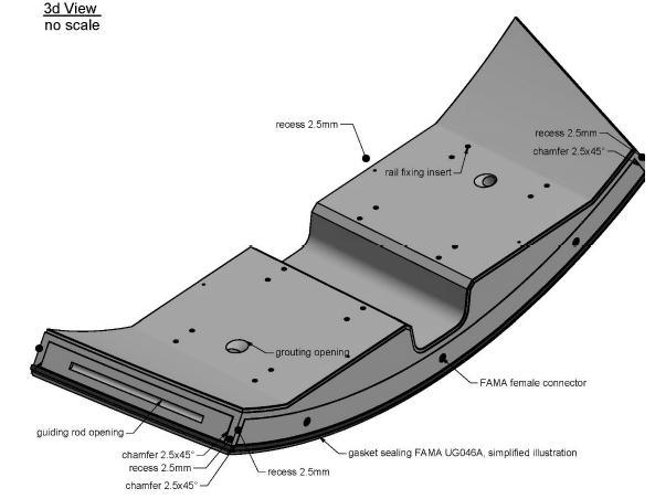
S1 – Invert segment
The trapezoidal invert segment with its designation “S1” is the first segment to be installed within the tail shield. The segmenthastwogroutingopeningslocatedintheflatinvertarea,wherealsorailfixinginsertsarelocated.Contactareais defined with a width of 190mm at longitudinal joint and circumferential joint. At corners between circumferential joint and longitudinal joint recesses are foreseen to avoid segment damage. The circumferential joint offers 3 connector openingsatleadingsideand5connectoropenings(3standardconnector+2openingsforAnixterBi-Cone)attrailingside. S1-Invert


S2 – Lower sidewall segment left
Thelowersidewallsegmentatleftside(inheadingdirection)iscalled“S2”andwillbeinstalledafterinvertsegment “S1”. Thesegmenthastwogroutingopeningsforpeagravelapplicationrespectivelyforgroutingpurpose.Thecircumferential joint is offering 4 connector openings (3 openings for standard connector + 1 opening for Anixter Bi-Cone) at trailing as wellasatleadingjoint.Forcentringpurpose,thesegmenthasasafetypininsert,fittedwithplasticinsertforproperfinal closure
S3 – Lower sidewall segment right
ThelowersidewallsegmentisshowingthesamecharacteristicsthansegmentS2,withadditionalfixinginsertstomount somecableandpipeholder.
S3 – Lower sidewall segment right
S4 – Upper sidewall segment left
S4 - Upper sidewall segment left
The upper sidewall segment left, designated as S4 is showing the same characteristics than segment S2, with additional fixinginsertstomounttheconveyorbelt.
S5 – Upper sidewall segment right
UppersidewallsegmentrightisshowingthesamecharacteristicsthansegmentS2.
S5 – Upper sidewall segment right
S6– Roof segment,


S6 – roof segment
The roof segment, designated as S6 is the key stone of the segmental lining system. Beside the two radially located grouting openings, in the top an additional inclined grouting opening is foreseen right in the centre line to increase the effectivityofpeagravelapplicationintheroofarea.Cornersbetweencircumferentialjointandlongitudinaljointarefitted witharecesstoavoidsegmentdamage.Theleadingcircumferentialjointiscontainingintotal5connectoropenings,3for standardconnectorand2forBi-Coneconnector,whileontrailingcircumferentialjointthe3standardconnectoropenings areforeseen.
1.7 SEGMENT JOINTS SEALING & SEGMENT REPAIR WORKS
SEALING
The next step during the normal activities (excavation and re‐gripping), in the range of the Back‐Up decks, the caulking grooveswillbeclosedwithmortarandallrepairworksisdone.Withinthesamestepthemajornumberofgroutingholes (about¾) isfilled witha repairmortarpriortocontactgrouting.Theremaingroutingholes laterarefittedwithpackers forgrouting.
SEGMENT REPAIR
Segmentscanbedamagedinoneofthethreefollowingphases:
1-Fabrication
2-Transporttothetunnel
3-Erection
Scopeofthisreportistodefinetheprincipleoftherepairprocedureofdamagesheldduringtheerection.
Two different types of damages can happen:
1-Edgebroken
2-Crackappeared
To repair breaking the following procedure may be used:
1. Concrete surface cleaning and broken concrete parts removing. By using chisel, concrete surface will have new roughness.
2.Washingbywaterwithpressure.
3.Removingofwaterexcesskeepingwettheparttoberepaired
4.Applyingofadmixtureaspersuppliertechnicalsheet
5.Applyingmorethanonelayerconsideringthateachlayerhasathickofmaximum20mm.thesubsequentlayerscanbe appliedwhenthepreviousisdriedout.
6.Attheendoftheoperationthesurfacewillbesmoothedoutbyspatula
7.Keepingwetthesurfaceforthenext24hours
Segment details
Inthefollowingsubchapterssegmentdetailswillbedescribedfurtherintermsof:
-Longitudinaljoint
-Circumferentialjoint
-Gasketsealing
-Groutingopenings
-Inserts
-Safetypinopenings
-Segmentmarkings
Longitudinal joint
The longitudinal joint is showing a flat contact area between two segments, where forces will be transmitted. Inside the symmetriccontactareaaguidingrodopeningislocated.Guidingrodopeningradiusisslightlybiggerthantheguidingrod itself,avoidingloadtransmissionoverguidingrod.Theintradosjointwillbeclosedwithmortartoimprovethehydraulic frictionbehaviour.Theintradosjointisdesigninaself-lockingprinciple,toavoidthatmortarwillfallintoturbinewater. Atextradossideofcontactareaagasketsealingislocated.
Longitudinal joint Circumferential joint with standard connector
Circumferential joint
Circumferential joint is showing a flat contact area between two segments, where piston forces will be transmitted. The intradosjointwillbeclosedwithmortartoimprovethehydraulicfrictionbehaviour.Theintradosjointisdesigninaselflocking principle, to avoid that mortar will fall into turbine water. At extrados side of contact area a gasket sealing is located.


Gasket sealing

Duetotenderrequirementsagasketsealingisrequiredtowithstandagainstawaterpressureof8.0bars.Forachievingthe requirements gasket sealing “FAMA U.G.046A” will be used. Considering the systematic gap referring to the technical specificationshowninAnnex1,therequiredpressureofp=8.0barcanbereachedwiththefollowinggaps:
-5.3mmatoffset0mm
-4.2mmatoffsetof5mm
-2.75mmatoffsetof10mm
Grouting openings
Grouting openings are required for the filling in process of pea gravel as well as for grouting purpose. Due to hydraulic reasonsallgroutingopeningsmustbe closedwithmortar.Duetotheshapeofthegroutingopeningsaself-lockingeffect ofthemortarplugispresent,preventingthemortarfromfallingintoturbinewater.

Grouting openings
Fixing inserts
Inserts
Twotypesofinsertsareusedinthecurrentsegmentallining.
T10insert
Railwayfixinginsert
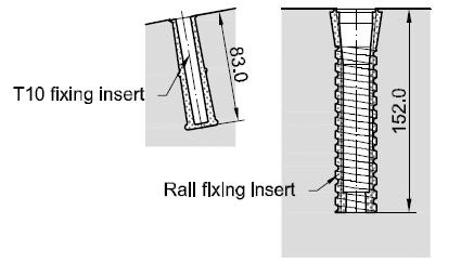

RailwayfixinginsertsareonlyusedatS1-Invertsegment,whileT10fixinginsertisusedfor allotherfixingpurposeasventilation,conveyor-beltandpipeholders.
Safety pin opening
Duetotheuseofvacuumerector,safetypinsopeningsarerequiredtotransmitshearforces (self-weightduringrotation)alongvacuumplate.
Safety pin opening
1.8 SEGMENT JOINTS SEALING & SEGMENT REPAIR WORKS SEALING
Within a next step and during the normal activities (excavation and re‐gripping), in the range of the Back‐Up decks, the caulking grooves will be closed with mortar and all repair works is done. Within the same step the major number of groutingholes(about¾)isfilledwitharepairmortarpriortocontactgrouting.Theremaingroutingholeslaterarefitted withpackersforgrouting.
Thematerialusedtosealthejointsbetweensegmentandringsare:PremixedmortarwithSikaMonotop‐622and/orSika Latex(mixdesignhastobestudiedinthejobsite);InspecialcasescouldbeusedSIKAIgasNeroorsimilarthemortaris used to fill‐up the grooves along the perimeter at the intrados. Grooves are shaped to capture mortar, avoiding any escaping toward tunnel. In a certain case, when water can flow from the bottom, along the perimeter of the invert Segment,isappliedacordofspecialproduct(IGASNEROSIKA)bituminouselastoplasticsealingagent.
1.9 Summary and final statement
The 13.40km long HRT (head race tunnel) of hydroelectric project Vishnugad Pipalkoti shall be excavated by a Double ShieldTBMandlinedwithasegmentallining.ThedesigndischargeisaboutQ=228m³/s,thereforeaninternaldiameterof øi=8.80m is foreseen. The foreseen rhomboidal gasket sealed segment system is composed of two trapezoidal segments (Invertsegmentandroofsegment)togetherwith4rhomboidalsegments.The350mmthicksegmentswillbebeddedwith bi component mortar in the invert and pea gravel in the remaining circumference, which will be modified with contact groutinginaseparatestep.Temporarydistanceboltsareforeseenforsecuringthesegmentallininguntilthefullbedding isavailable.Toachievequitea smoothhydraulicbehaviourall jointsandlargediameteropeningshavetobeclosedwith mortar. Guiding rods in longitudinal joints and connectors in circumferential joints are helping to achieve an accurate segmental lininginstallation.Anessential partofthesegmental liningofVPHEPHRTisthegrouting procedure. Overthe entire tunnel systematic contact grouting on cement basis will be applied. In special stretches borehole grouting for consolidation, sealing or intervention purpose will be applied on cement basis. For intervention grouting also chemical grouting material are common. The proposed method is considered to be most economic and has proved to work in practice.
1.10. CONCLUSIONS
Inthisresearchpaper,weanalysedtheroleofSegmentsintunnelmanagement.
We found that such technologies, such as segmental lining with the help of TBM have the potential to significantly improveprojectcompletiontimingwhilemaintainingthequalitystandards.
Thesesystemsusearangeoftechnologies,includingsensorsintunnelswhichareusedformonitoringthemovement ofhill,communicationsystems,anddata analysistools,togatherandthedata andprovidetimelyinformation tothe agencies.
Thiswork focuseson thecrucial featuresthatshouldbeincorporatedintothe numerical model when examiningthe responseofasegmentallinerwhichisgenerallyemployedinguard-driventunnelling.
Theinvariantringmodelhasbeenextensivelyusedindesignpracticeofshielddrivenroundtunnelinsoftgroundduetoitssimplicity.
SpecialisedTBMisequippedtoconstructtunnelinhighlyabrasivegroundwithoutimpactingthegroundsnearby.
REFERENCES
[1] Contract Agreement for EPC Contract for Civil works and Hydro-Mechanical Equipment works Including Penstock SteelLiners,VishnugadPipalkotiHEProject(4*111MW)withM/sHindustanConstructionCompanyLimitedMumbai (India).
[2] Studiesonthekeyparametersinsegmentalliningdesignby-ZhenchangGuan,TaoDeng,GangWang,YujingJiang.
[3] TunnelSegmentGasketdesign–solutions&innovations-Bakhshi,Mehdi,andNasriVerya.
[4] Sealingofjoint,NeilWilliamson,inAdvancedConcreteTechnology,2003.
[5] Tunnelboringmachinerockdrilling&boringZong-XianZhang,inRockFractureandBlasting,2016
[6] IS:4756-1978(reaffirmed2002).Safetycodefortunnellingwork