Static, Dynamic and Life Evaluation of Submersible Pumps
Yashas S1, Chandan R2 , Shivu G M3
1,3M.Tech. Student, Dr Ambedkar institute of Technology
2Assistant Professor, Dept. Of Mechanical Engineering

Dr Ambedkar Institute of Technology, Bangalore, India
Abstract - A pump is a device that mechanically transfers fluids (and gases). It’s device that converts mechanical energy into water-powered energy. According to this method they employ to convey the liquid, pumps can be categorized into three distinct groups: direct lift, uprooting, and gravity pumps. The rotating component of a radiating pump is called an impeller. It is made up of a series of reverse-bent vanes. The present works goal is to design and perform static, modal analysis and life evaluation of submersible pump impeller utilizing a variety of materials mostly conventional ones such as CFRP and Al 2014 alloy. The Geometric CAD model of an impeller is done using CATIA and for analysis (FEA) ANSYS WORKBENCH is used. This work is projected to reduce the cost and to increase the weight to strength ratio.
Key Words: Static analysis, Pump Impeller, FEA, Submersible Pump
1. INTRODUCTION
Apumpisadevicethatmechanicallytransfersfluids(gases orfluids)oroccasionallyslurries.It’sdevicethatconverts mechanicalenergyintowater-poweredenergy.Accordingto thismethodtheyemploytoconveytheliquid,pumpscanbe categorizedintothreedistinctgroups:directlift,uprooting, andgravitypumps Pumpsoperateusingavarietyofpower sourcesincludingasmotors,manuallabor,windcontrolor electricity. Other words for pump include "water driven energyintomechanicalenergy"and"mechanicalenergyinto pressuredrivenenergy”. Theprimaryusesofsubmersible pumpsareinagriculture,windcontrol,businessventures, waterstorage,andotherapplications
The rotating component of a radiating pump is called an impeller.Itismadeupofaseriesofreverse-bentvanes.Ona polethatisconnectedtothepoleofanelectricengine,the impeller is mounted. An impeller is a rotor that is placed inside a cylinder or channel and used to increase (or decrease,intheeventthatturbinesarepresent)theweight andstreamofaliquid
Themajorityofcentrifugalpumpimpellersaremadeofmild steel, which has a higher density. The main cause of the pump'sweightisthis.Moreover,ithaslowfatiguestrength andahighrateofcorrosion.
Toreduceweight,enhancecorrosionresistanceandincrease fatiguestrengthincomparisontootheralloys and composite materials, alloy material (such as stainless steel, Inconel, aluminium alloys) can be used in place of mild steel. In comparisontocompositematerialsanddifferentalloys,the same material produces greater deformations since it has lessstiffness.
1.1 Literature Review
ASyamPrasad,BVVVLakshmipathiRaoetal[1]herein this work they have discussed various engineering application of alloys. This study examines the static and dynamic performance evaluation of a centrifugal pump impeller built of three distinct alloy materials (Warpaloy, Inconelalloy803,andInconelalloy740).Structuralanalysis hasbeenperformedtoinvestigatethestrains,stresses,and displacementsoftheimpeller,andamodalanalysishasbeen used to investigate the frequency and deflection of the impeller. By comparing the outcomes achieved for three distinct alloys, an attempt is also made to recommend the optimalalloyforanimpellerofacentrifugalpump.
KarthikMatta,KodeSrividyaetal[2]hereinthispaper they have discussed the impeller, a rotating part of a centrifugal pump often made of iron, steel, bronze, brass, aluminum,orplastic,acceleratesthefluidbeingpushedaway fromthecenterofrotationinordertotransmitenergyfrom themotorpoweringthepumptothefluidbeingpumped.Itis suggested that a blower be designed utilizing composite material,andthatitsstrengthanddeformationbeexamined usingFEMsoftware.UsingpackagedFEA(ANSYS),compare the performance of metal blower and impeller with composite materials. The first five natural frequencies are discovered using a modal analysis on a centrifugal blower impellermadeofaluminumandcomposite.
G.Kalyan,K.L.N.Murtyetal[3]hereintheirstudythey havediscussedthatitisessentialforthecost-effectivedesign ofpumpstoforeseetheirperformancebeforeconstructing them,whichnecessitatesknowledgeoftheflowbehaviorin various pump components. Aluminum and steel are the materialsusedinimpeller.BothstructuralanalysisandCFD analysisare carried out.Byobserving the outcomes of the analysis that was done, the impeller design is optimized. Resultsforstress,frequency,velocity,andpressureflowrates aretakenintoaccount.AnalysisisperformedthroughAnsys.
Pramod J. Bachche1, R.M. Tayade et al [4] here in this paper they have discussed that one of the oldest waterpumpingdevicesinuseisthecentrifugalpump.Considerthe ShaftofaRadialPumpforbothstaticanddynamicanalysisin thisstudy.Twostagesmakeuptheentireproject.Thefirst stage is a static examination; this stage involves disassembling the pump shaft to check for tensions and redirection,andutilizingagraphicalinclusiontechniqueto confirmthesameoutcomes.Additionally,theresultsofthe staticinquiryareusedatthispointtocalculatethedynamic powers entering the pump shaft for the dynamic examination.Theleaststreamconditioniscreatedwiththe mostredirectionandstress.Maximumconcernsfordynamic areobtainedat11%notexactlyallowablediversionand18% not exactly allowable elasticity, respectively, for the most severeuniqueavoidance.
S.Rajendran,Dr.KPurushothamanetal[5],inthispaper discussed using the ANSYS software, a three-dimensional, completelyturbulentmodelofthecompressibleflowpastan impellerwithacomplicatedshape,similartothoseseenin centrifugalpumps,wascreated.Intheirwork,theflowofa centrifugalpumpimpellerissimulated.ANSYS-CFXisusedto analyze the design of the impeller for a centrifugal pump. ANSYS-CFXcanaccuratelyestimatethecomplicatedinternal flows in the centrifugal pump impellers. The standard incompressibleNavier-Stokesequationsinthreedimensions are numerically solved on an unstructured grid using an ANSYS-CFX. This study discusses the flow pattern, blade loading, pressure graphs, and pressure distribution throughoutthebladepassage
Sampath Kumar, Dsvsra Vara prasad et al [6] in their studydiscussedcentrifugalblowersisusedinenginesthat have high noise levels and in maritime applications. This paperexaminesoutwardblowersusingcompositematerials using static and model analysis. The current study investigates if using E-Glass instead of metal will improve vibration management. E-Glass, which is renowned for its unmatcheddampeningqualities,isalsoencouraginginterms of vibration reduction when compared to metals. The EGlass/Epoxy blower concerns discovered during the static inspectionarewithintheacceptablepressurerange.Because of the higher firmness, the typical recurrence of E glass blowersisdecreasingfrom16.6%to27.7%.
GundaleV.A.,JoshiG.R. [7]inthispapertheydiscussed the completepictureoftheradial type vane profile design method. . In this work, the vane profile was constructed without changing the overall dimensions of an existing impeller.The3Dmodelwasmadeusingcommercial3DCAD software. This strategy will motivate pump designers to improvethefunctionalityofbothcurrentandfutureversions.
ShyamKaranth,V.K.Havanur[8]intheirworkdiscussed how to improve the model G554T pump’s efficiency and hence its overall efficiency. Pump efficiency and motor
efficiencytogethermakeuptheoverallefficiency.Analyzing thecurrentmodelG554Tandfiguringoutitscurrentoverall efficiencycomesfirst.Thesecondphaseentailsredesigning the pump such that more power can be produced for the sameamountofpowerinput.SOLIDWORKShasamodelof thenewpumpdesign.Inordertoincreaseoverallefficiency, themodeledpumpisexaminedusingANSYS,andthenthe newlydevelopedpumpisassessedandapproved
FarahElidaSelamat,WanHarizIskandarWanIzhan[9], Thispaperfocusesontheideaofcentrifugalpumpdesign& research to enhance pump performance within the pump parameters.ANSYSCFXwasusedfordesignandsimulation, withtheNavier-Stokesequation.Forthisproject,theshear stresstransport(SST)turbulencemodelwasemployed.As theimpeller'srotationalspeedincreases,thepressureinside theimpellerrises,ascanbeseenfromthesimulationresults. Fromtheimpellerinlettotheimpelleroutlet,thepressure risesgradually.Additionally,itisevidentthatasrotational speed rises, impeller efficiency rises. When a result, as efficiency rises, so does the impeller's performance. The performance of the impellers was compared based on the inlet and outlet power, impeller performance, pressure distribution,andstaticheadpressureproduced.
S.Mayakannan, V. Jeevabharathi et al [10] in this paper theydiscussedthatinordertoboostthepowerandefficiency ofacentrifugalcausticslurrypump,theimpellershouldbe designed.Theimpactoftemperature,pressure,andinduced stressesontheimpellerhasbeenattemptedtounderstand. Long-termstabilityandextendedservicelifeareguaranteed bydefiningthetruedesigncharacteristic.Theheatflowand directionoftheimpeller'sheatfluxhavebeeninvestigatedby athermalstudy.Bycontrastingtheoutcomesfortwodistinct materials .Inconel alloy 783 and Inconel alloy 740 for centrifugalistobemanufacturedandanattemptisalsomade tosuggesttheoptimummaterialforanimpeller.Theideal materialforaturbochargerimpellerissuggestedbasedon results.
1.2 Objectives
This works main objective is to perform structural analysisunderstaticanddynamicloadcircumstancesand pumplifeevaluation.
Geometric modelling is developed to validate the stress and deformation using analytical equations.
Static structural evaluation of the submersible pumpimpeller
Modalanalysisofsubmersiblepumpimpeller.
Modalanalysisofsubmersiblepumpimpeller.
Lifeevaluationofimpeller(Fatigueanalysis).
2. Methodology
Theimpellerismadeinaccordancewiththerequirements establishedbySiTarc,arenownededucationalorganization that provides information on pumps. Prior to starting the designprocess,theperformancedataforthepump'smotoris gathered. The design factors presented are based on a theoretical framework and extensive data collection over manyyearsinvolvingthousandsofperformancetesting.
The blade needs to be built to handle 2100GPM of discharge and a head that is 450 feet long and rotating at 3600RPM.Someofthenecessarydataarepresumptive.The impellerbladeiscreatedasshownbelow.
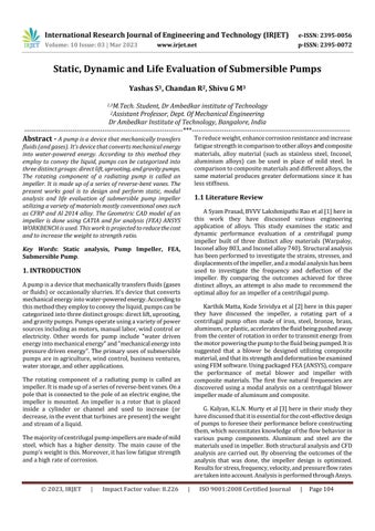
Table-1:Dimensions
Theabovefigureshowsmeshingonimpellerofsubmersible pump. Meshing used is hexagonal mesh metric, statistic nodesis57644andelements18015.UsingAnalysissoftware ANSYSWORKBENCH.
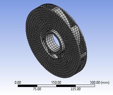
Table-2 Numberofelementsandnodes

BoundaryCondition
2.2 Modeling of Submersible pump
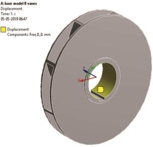
Fig-3: Impellerdisplacementinxaxisandyaxisand constraininzdirection
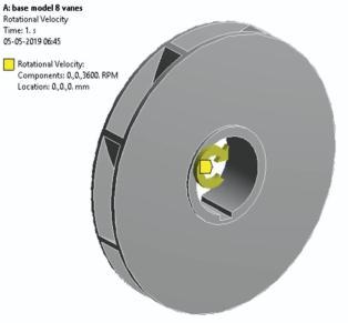
Apply load condition is Rotational velocity and the displacement.Thewaterpressureshouldemergeinpump,to createpressureimpellermustbeinratiocertainRPMasper analyticalcalculation,androtationalvelocityis3600RPM
3. Static Analysis of Submersible Pump Impeller
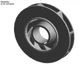
3.1 Static Analysis of Structural Steel
Maximum Equivalent (von-mises) Stress
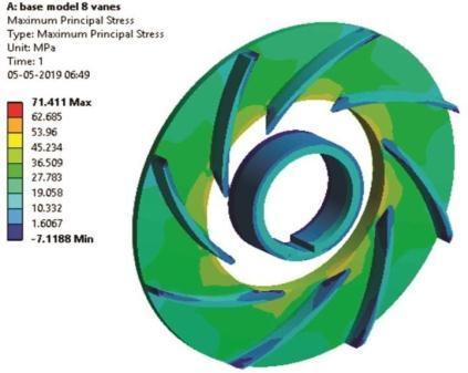
Maximum Principal Stress
3.2 Static Analysis of Aluminum 2014 alloy
Maximum Equivalent (von-mises) Stress
Fig-5: MaximumPrincipalStressofSSimpeller
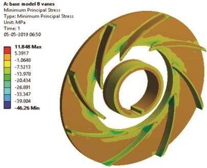
Minimum Principal Stress
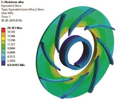
Fig-8: MaximiumEquivalentstressforAl2014 Impeller
Maximum Principal Stress
Fig-6: MinimumPrincipalStressofSSimpeller
Total Deformation
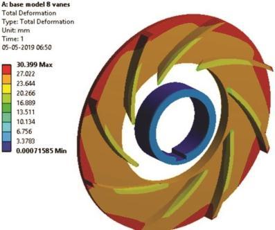
Fig-7: MaximumTotaldeformationofSSImpeller
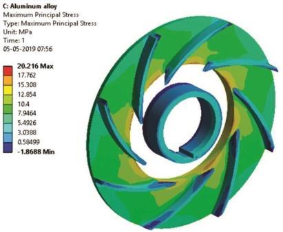
Fig-9: MaximumPrincipalStressofAl2014 Impeller
Minimum Principal Stress
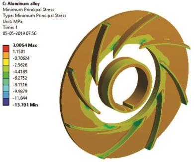
Fig-10: MinimumPrincipalStressofAl2014 Impeller
Total Deformation
Fig-11: MaximumTotaldeformationofAl 2014Impeller
3.3 Static Analysis of CFRP Impeller

Maximum Equivalent (von-mises) Stress
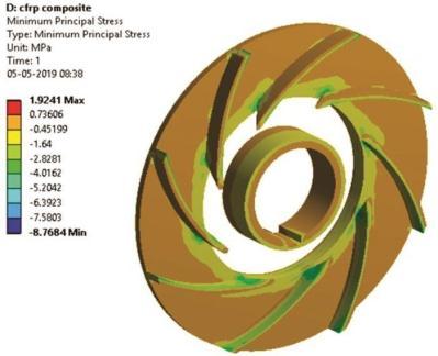
Minimum Principal Stress
Fig-14: MinimumPrincipalStressofCFRP impeller
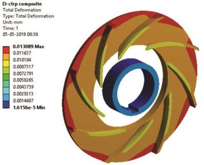
Total Deformation
Fig-15: MaximumTotaldeformationofCFRP Impeller
3.4 Results and Discussion
Fig-12: MaximumEquivalentStressofCFRP Impeller
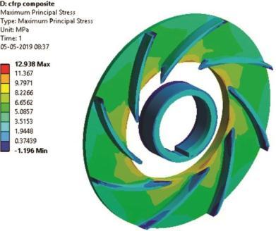
Maximum Principal Stress
Fig-13: MaximumPrincipalStressofCFRPimpeller
Table-3: EvaluationofMax&MinPrincipalStressand equivalentstress.
Evaluationofdeformationandweightreduction.
If we look at the results above and compare the corresponding deformation of the SS material to the corresponding deformation of the Al 2014 alloy and the CFRPcompositematerial,theCFRPcompositematerialhas theleastamountofdeformation,sotherearefewerchances that the pump impeller will fail than with the SS and aluminum materials. As a result, the CFRP composite materialincreasesthepump'sstrength.BecausetheCFRP compositematerialpumpimpeller(3.9Kg)weighslessthan theSS(5.58Kg)material,theweightofthepumpimpeller was reduced. Hence, the pump impeller's weight is significantlydecreased.
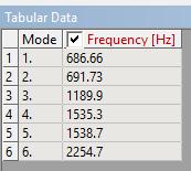
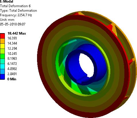
3.5 Modal Analysis of CFRP Pump Impeller
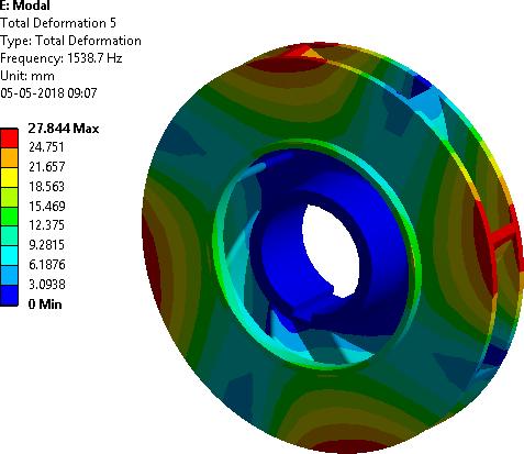
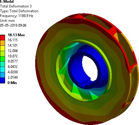
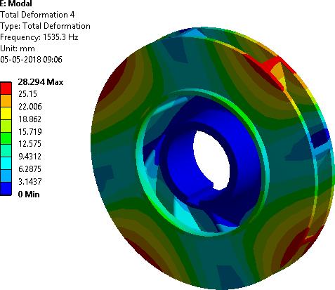
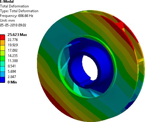
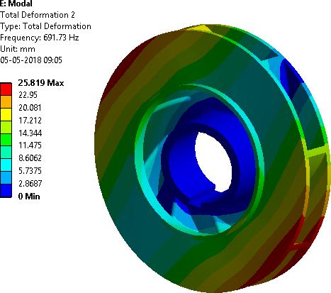
Itiscommonforspecificationsforrotatingequipmentwith significant dynamic loads to demand that no structural modesexistwithinagivenfrequencyrange.Itisfrequently quite difficult to do dynamic analysis of complex floor systemsusingcomputerfiniteelementmethods.Duringthe design of the pump in a different process, rotating equipmentwasaworry.Thesepumpsneededalotof freespaceunderneaththembecausetheyweregoingtobe subjecttostrongdynamicforces.Foreachoftheimpellers,a rangeofsupportandrestraintsystemsweremodeledusing finiteelementanalysis.
3.6 Life Evaluation Results
Thefatiguelifeofaspecimenisthetotalnumberofcyclesof loading(stressorstrain)itcanwithstandbeforefailing.Low cyclefatigueisdefinedastheregionbetween104 and105 load cycles High cycle fatigue is the highest stress that a materialcanendureunderrepeatedcyclicloadingwithout immediatelyfailing
σ
σ
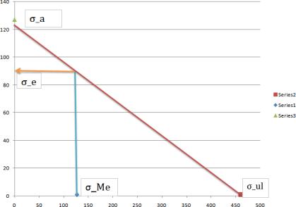
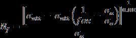
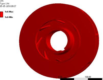
The figure-21 indicates the life evaluation of the pump impellerdoneusingANSYSwhichis106 cycles. Meanstresscanbecalculatedfrom
fos=FactorofSafety
σe=Endurancelimit
b=Fatiguestrengthexponent
σa=Alternatingstress
Nf =1.554×10⁶
Theresultingfatiguelifeobtainedbyanalytical methodisgreaterthan 105 Cycleshenceitishigh cyclefatigue.
3. CONCLUSIONS
Accordingtostaticandmodalanalysisofthepump impeller, the maximum deflection that can be caused in a metallic pump impeller made of SS material is 3.00mm, which is within working limits. With consideration of working limit, the maximum induced stress for the SS materialis71.02Mpa,whichislessthanthepermittedstress (340Mpa).Therefore,basedonstrengththedesignissecure. Withconsiderationofworkinglimit,themaximuminduced stressfortheSSmaterialis71.02Mpa,whichislessthanthe permittedstress(340Mpa).Therefore,basedonstrengththe designissecure.Ifwelookattheresultsaboveandcompare the corresponding deformation of the SS material to the
corresponding deformation of the Al 2014 alloy and the CFRPcompositematerial,theCFRPcompositematerialhas theleastamountofdeformation,sotherearefewerchances that the pump impeller will fail than with the SS and aluminum materials. As a result, the CFRP composite materialincreasesthepump'sstrength.BecausetheCFRP compositematerialpumpimpeller(3.9Kg)weighslessthan theSS(5.58Kg)material,theweightofthepumpimpeller was reduced. Hence, the pump impeller's weight is significantlydecreased.
REFERENCES
[1] ASyamPrasad,BVVVLakshmipathiRao,ABabji,DrP Kumar Babu, “Static and Dynamic Analysis of a Centrifugal Pump Impeller” International Journal of Scientific&EngineeringResearch,Volume4,Issue10, October-2013,pp966-971.
[2] KarthikMatta,KodeSrividya,InturiPrakash,“Staticand Dynamic Response of an Impeller at Varying Effects” IOSR Journal of Mechanical and Civil Engineering (IOSRJMCE) e-ISSN: 2278-1684, p-ISSN: 2320-334X, Volume11,Issue1Ver.IIIpp101-106(Jan.2014)
[3] G. Kalyan K.L.N. Murty, "Design and Optimization of Centrifugal Pump Guide Vanes,"SSRG International JournalofMechanicalEngineering,vol.2,no.2,pp.9-14, 2015.
[4] Pramod J. Bachche1, R.M.Tayade, “ Finite Element AnalysisofShaftofCentrifugalPump”IOSRJournalof MechanicalandCivilEngineering(IOSR-JMCE)e-ISSN: 2278-1684,p-ISSN:2320-334X,Volume7,Issue3(JulAug.2013),pp37-42.
[5] S.Rajendran and Dr. K Purushothaman, “Analysis of centrifugal pump impeller using ANSYS-CFX” International Journal of Engineering & Technology (IJERT)Vol.1Issue3,May-2012pp1-6.
[6] M. Sampathkumar, Mr.Dsvsra Varaprasad, Mr.Vijaykumar, “Static Analysis of Centrifugal Blower UsingCompositeMaterial”TheInternationalJournalOf Engineering.
[7] Gundale V.A., Joshi G.R., “A Simplified 3d Model Approach in Constructing the Plain Vane Profile of a Radial Type Submersible Pump Impeller”, Research JournalofEngineeringSciences,Vol.4,July2013,PP.3337.
[8] Shyam Karanth, V. K. Havanur, “Design, Modeling & Analysis of a Submersible Pump and to improve the PumpEfficiency”InternationalJournalofLatestTrends inEngineeringandTechnology(IJLTET).
[9] FarahElidaSelamat,WanHarizIskandarWan,“Design and Analysis of Centrifugal Pump Impeller for Performance Enhancement”, Journal of Mechanical Engineering,VolSI5(2),35-53,2018.
[10] S.Mayakannan, V.Jeevabharathi, R.Mani, M.Muthuraj, “DESIGN AND ANALYSIS OF IMPELLER FOR CENTRIFUGALPUMP”,IJARIIE-ISSN(O)-2395-4396,Vol2Issue-1,2016.
[11] HarishR,ChandanR,PrahaladW,ShivappaHA,“Design and Analysis of Machine Tool spindle for Special PurposeMachines(SPM)andStandardizingtheDesign usingAutodeskInventor(I-logic)”InternationalJournal forIgnitedMinds(IJIMINDS)vol02,Issue:09.
[12] Deepak J N, Chandan R, Doddanna K, “Design & Structural Analysis ofa Small Wind TurbineBlade for OperationatLowWindSpeed”,InternationalResearch JournalofEngineeringandTechnologyvolume04,issue: 11