Importance of Non-Dimensional Slenderness Ratio in the Design of Compression and Shear members as per IS 800:2007
M. Lincoln Babu1 & Dr. B. Krishna Rao21M Tech student, Dept. of Civil Engineering, University College of Engineering Kakinada (Autonomous), Jawaharlal Nehru Technological University Kakinada, Kakinada, Andhra Pradesh, India.

2Professor, Dept. of Civil Engineering, University College of Engineering Kakinada (Autonomous), Jawaharlal Nehru Technological University Kakinada, Kakinada, Andhra Pradesh, India.
Abstract - In steel design, Indian standard code of practice defines a parameter i.e., non-dimensional slenderness ratio, which is defined as ratio of yield strength to the critical stress. When a member is subjected to compressive force then compressive strength is calculated by the column buckling curve and Euler’s buckling theory is an important consideration. In this, non-dimensional slenderness ratio is defined as the ratio of effective length to the corresponding radius of gyration. When a beam is subjected to shear force then the shear force is resisted by the web only. For this consideration, shear buckling of the web with or without intermediate stiffeners is considered in the designofthe beam. Shear strength of beam is calculated by two methods - Simple Post Method and Tension Field Method. In the simple post method, the non-dimensionless slenderness ratio plays a major role. In the current study, I-sections with varying parameters i.e, length in x, y direction & c/d ratio were designed for Compression and Shear respectively. The design procedure was carried out in the Excel. The results were tabulatedfor the members designed for compression and shear. The graphs were also plotted for various parameters v/s Slenderness ratio. It is studied that if d/tw > 67ϵ then the web portion is neglected in the calculation of Moment of Inertia and shear buckling takes place. The results show that the slenderness ratio is indirectly proportional to the c/d ratio in shear members.
Key Words: Steelstructures,Non-dimensionalslenderness ratio,Simplepostmethod,Compression,Shear,Excel.
1. INTRODUCTION
A structural member which is subjected to compressive forcesalongitsaxisiscalleda Compression member. Thus, compression members are subjected to loads that tend to decrease their lengths. Except in pin-jointed trusses, such members(inanyplaneorspacestructure),underexternal loads,experiencebendingmomentsandshearforces.Ifthe net end moments are zero, the compression member is required to resist load acting concentric to the original longitudinal axis of the member and is termed as Axially loaded column, orsimply column.
Shear force generally exists with bending moments, the maximumshearstressinabeamistobecomparedwiththe shearyieldstress.SincethewebofanI-beamisessentiallya
plate,itmaybuckleduetoshearingstresseswhichareless thantheshearingyieldstrengthofsteel.Inaplatesubjected topureshear,theshearstressesareequivalenttoprincipal stresses of the same magnitude, one tension and another compression, acting at 45 degrees to the shear stresses. Buckling takes place in the form of waves or wrinkles inclinedataround45degrees.
1.1 SLENDERNESS RATIO
It is definedasthe ratioof the effective length(Le) ofa member to the radius of gyration (r) of the cross-section abouttheaxisunderconsideration.Itisrepresentedas
Italsodefinesthefailuremodeofthecolumnbasedonthe effectivelengthandtheradiusofgyration.Itisageometrical parameter,definedforacompressionmember(column).Itis alsoameasureofthestructuralvulnerabilitytothefailureof thestructure.
1.2 EFFECTIVE LENGTH
Theeffectivelength(Le)isthelengthbetweenthepointof zeromomentorsuccessiveinflectionpoints.Zeromoments is the point at which the moment becomes zero. It is also referred to as the Inflection point. In other words, the effectivelengthofacolumninagivenplanemaybedefined as the distance between the points of inflection (zero moment)inthebuckledconfigurationofthecolumninthat planeasshowninbelowfigure.Theeffectofendrestraints oncolumnstrengthisusuallyincorporatedinthedesignby theconceptofeffectivelength.
1.3 RADIUS OF GYRATION
Radiusofgyrationorgyradiusofabodyabouttheaxisof rotation is defined as the radial distance to a point which would have a moment of inertia the same as the body's actualdistributionofmass,ifthetotalmassofthebodywere concentratedthere.Thedistancefromanaxisatwhichthe massofabodymaybeassumedtobeconcentratedand at whichthemomentofinertiawillbeequaltothemomentof inertiaoftheactualmassabouttheaxis,equaltothesquare rootofthequotientofthemomentofinertiaandthemass.
2. METHODOLOGY
The entire work is divided into two parts i.e., Design of CompressionmembersandDesignofShearmembers.The design templates were formulated in Excel software. The design procedure in both the cases is done as per Indian Standard code of IS 800:2007. From the obtained design results,drawthebucklingcurve,variousrelationshipcurves i.e, v/s , v/sc/detc.
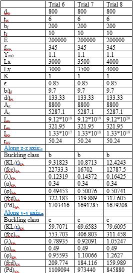
For a given welded I section with the following data, calculateitscompressioncarryingcapacity

Overalldepthofthebeam=800mm
Thicknessofweb=6mm
Widthofflange=200mm
Thicknessofflange=10mm
LengthinX&Ydirectionis500,600,700,800,900,1000, 1400,1800,2200,2600,3000,3500&4000mm
Thicknessofweb=10mm
Widthofflange=275mm
Thicknessofflange=12mm
3. RESULTS & DISCUSSIONS
ThedesignprocesswasformulatedinExcelforcompression andshear.Thedesignprocesswascarriedoutforeachtrail inallthedesignprocedures.Theresultsthusobtainedare tabulatedasbelow.Also,thegraphswereplottedforvarious parameters to study the relationship of non-dimensional slendernessratiowiththeotherparameters.
3.1 COMPRESSION CAPACITY
Theobtainedcompressioncapacitydesignedresultswere asshowninthetablesbelow.
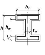
Fig -1:WeldedI-sectiontofindoutthecompressionand shearcapacity
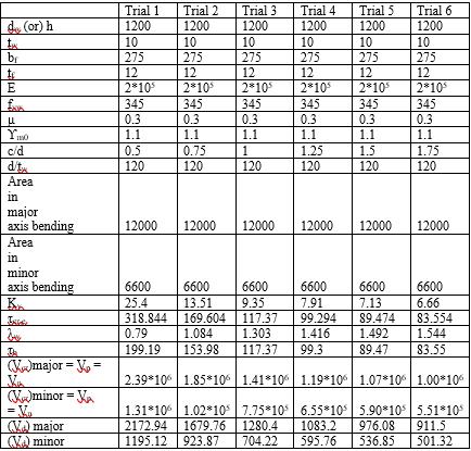
For a given I section with the following data, calculate its shearcapacity
Depthofthebeam=1200mm
From the graph as shown in Chart-1, we can see that the curve resembles the Buckling curve c. The buckling class abouty-y axisiscandhenceitresemblesthatcurve.Asthe fcd/fy increases, non-dimensional slenderness ratio is decreasing.Itcanbeseenthatboththefactorsareindirectly proportional to each other. It is due to the lot of imperfections.

3.2
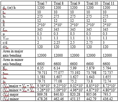
The obtained shear capacity designed results were as showninthetablesbelow.
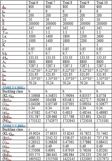 Table -2:Compressioncapacitycalculations-2
Table -3:Compressioncapacitycalculations-3
GRAPH:-
Chart -1:Bucklingcurve
SHEAR CAPACITY
Table -2:Compressioncapacitycalculations-2
Table -3:Compressioncapacitycalculations-3
GRAPH:-
Chart -1:Bucklingcurve
SHEAR CAPACITY
GRAPHS:-
We can observe that the design shear force is inversely proportionaltothec/dratioasshownintheChart-2.
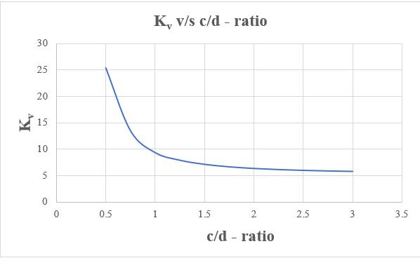
From the graph as shown in Chart-3, as the c/d ratio increases,shearbucklingconstantisdecreasing.


Chart
)
FromWhenslendernessratiogoesonincreasingtheother parameter elastic critical shear stress of the web is decreasingasshowninChart-4.
4. CONCLUSIONS
Based on the research and discussions, the following conclusionsweredrawn.AccordingtoIndianStandardsteel codeIS800:2007,whenamemberisdesignedforshearand compressionthenthenon-dimensionalslendernessratioλw andλisdefinedineachcaserespectively.
COMPRESSION:-
Incompressionpointofview,thereareonlysemicompactandslendersections.
If >42ꞓthenthegivensectionisslendersection.
If the section is slender then we consider the effectivearea,Ae i.e.,Ae =Ag -
For the considered design problem, the flange is semi-compact and the web is slender section. Hence, the overall section which is considered is slendersection.
Least KL/r value gives the maximum design compressiveforceandthehighestKL/rvaluegives theminimumdesigncompressiveforce
Ifthenon-dimensionaleffectiveslendernessratiois morethenwegettheminimumdesigncompressive force.
The least design compressive force which is obtainedinthecompressiondesigncalculationin both Y & Z directions is considered as its design compressiveforce.
Thebucklingclassaboutthey-yaxisisc.
Theobtainedcurveresemblesthebucklingcurvec asshowninFig.8inIS800:2007.
SHEAR:-
If <67ꞓthennoshearbucklingtakesplace.
If >67ꞓthenshearbucklingtakesplace.
Ifshearbucklingtakesplaceusesimplepostcritical methodortensionfieldmethod.
Incaseofshear,whenλw <0.8,0.8<λw <1.2,λw > 1.2thentheshearstrengthiscalculatedbydifferent formulaeaccordingtoIS800:2007
For the considered design problem, the flange is semi-compact and the web is slender section. Hence, the overall section which is considered is slendersection.
Shearstrengthisinverselyproportionaltoc/dratio.
Slendernessratioisinverselyproportionaltoelastic criticalshearstress.
Based on all the above results and conclusions, we can understand that the slenderness ratio plays an important roleindesignthememberssubjectedtocompressionand shearasperIS800:2007
REFERENCES
[1] Yuhan Nie, Yang Wei*, Linjie Huang*, Ying Liu and Fenghui Dong. (2021). Influence ofslenderness ratio andsectional geometry ontheaxial compression behavioroforiginalbamboocolumns.JournalofWood Science,pp.1-20.
[2] Iloegbu L. B, Chidolue C. A, Ezeagu C. A (2019). The EffectsofDesignMethodsonCompressiveMembersin Steel Frame Work. Iconic Research and Engineering Journals, Vol.2,Issue8,pp.86-94
[3] VidhiChopra,Dr.MohanGupta(2019).DesignaidtoIS 800-2007 : Safe load for Angle struts. International Research Journal of Engineering and Technology(IRJET), Vol.6,Issue6,pp.2812-2816.
[4] Shaiv Parikh (2013). Design Of Steel Compression Members(AccordingToIs:800). InternationalJournalof Engineering Research & Technology (IJERT),Vol.2,Issue 11,pp.1411-1417.
[5] Gargi Dandade (2021). A Brief Study on Different Stresses of Steel Structural Member as per Indian StandardParallelSection.ResearchandReviews:Journal ofEngineeringandTechnology(RRJET),Vol.10,Issue8, pp.1-5
[6] IS800:2007,IndianStandardGeneralConstruction Steel–CodeofPractice.
[7] Dr.N.Subramanian,“DesignofSteelStructures”, Oxfordhighereducation,Chennai(2008).
[8] DesignofsteelstructurebyS.Ramamrutham.
[9] DR.S.R.SatishKumarandA.R.SanthaKumar,“Beam column,StructuralEngineeringLaboratory,Dept.,of CivilEngineering,IITMadras,Chennai.
https://www.researchgate.net/profile/Satish-Kumar19
[10]TheoryofStabilityofStructuresbyAlexanderChaJes.
[11]TheoryofElasticStabilitybyS.P.Timoshenko&J.M. Gere‐McGrawHillPublications