
International Research Journal of Engineering and Technology (IRJET) e-ISSN: 2395-0056
Volume: 12 Issue: 05 | May 2025 www.irjet.net p-ISSN: 2395-0072


International Research Journal of Engineering and Technology (IRJET) e-ISSN: 2395-0056
Volume: 12 Issue: 05 | May 2025 www.irjet.net p-ISSN: 2395-0072
J Rajeshwari, G. Sushmitha, J. Keerthi, Shayeera Naaz
B.E Student, EEE, STLW, Telangana, India
B.E Student, EEE, STLW, Telangana, India
B.E Student, EEE, STLW, Telangana, India
Assistant professor, Dept. of EEE, STLW, Telangana, India
Abstract- Utilizing renewable energy sources helps decrease dependence on fossil fuels. When solar photovoltaic (PV) panels or wind turbines are generating electricity,theiroutputisdirectlysuppliedtothepowergrid. Inperiodswhentheserenewablesourcesareunavailable, dieselgeneratorsareused,butoveralldieselconsumptionis reduced. However, the integration of nonlinear loads can lead to fluctuations in wind speed and sudden drops in source voltage at the grid level. To address these power qualityissues,aUnifiedPowerQualityConditioner(UPQC) canbeemployed.TheUPQCoperatesbasedonthevoltage maintained across a DC-link capacitor. For optimal performance, it is essential to keep this capacitor voltage stable.TheaimoftheproposedstudyistofeedtheUPQC’s DC link capacitor using energy from solar PV or wind sources.ThissetupenablestheUPQCtofunctioneffectively for power quality improvement by maintaining proper voltagelevels.Thesystemismodeledandsimulatedusing theMATLABSimPowerSystemstoolbox.Themaingoalsof thisprojectincludeenhancingpowerqualitybymitigating voltage sags, swells, interruptions, and load current harmonics,whilealsoimprovingfuelefficiency.Additionally, theUPQCsupportscompensationofbothactiveandreactive power,contributingtoamorereliableandefficientenergy system.
Key Words: UPQC, PV Solar array, PMSG,MPPT,BMS,DG, Shunt inverter, Series Inverter
1.INTRODUCTION
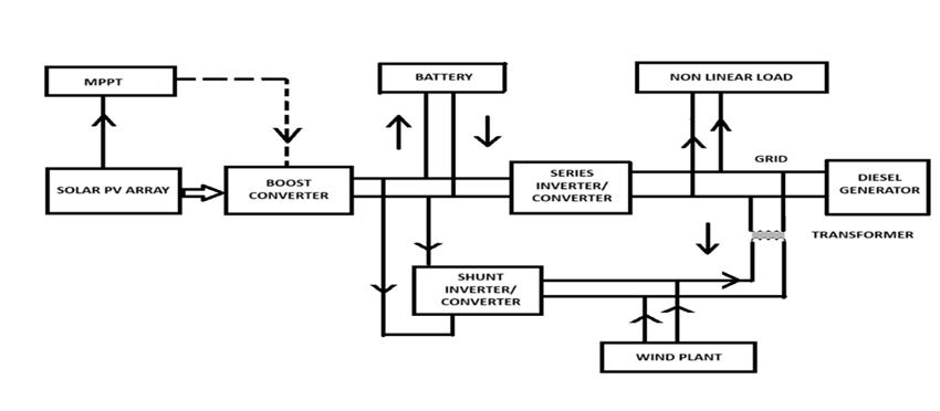
Amicrogridthatintegratesadieselgenerator(DG),awindpowered Permanent Magnet Synchronous Generator (PMSG),andasolarphotovoltaic(PV)arrayformsahybrid energysystemdesignedtooptimizeenergyproductionand usage while minimizing diesel fuel consumption. This combinationofconventionalandrenewableenergysources enhancesreliability,reducesemissions,andpromotescosteffectiveenergyutilization.
The system also includes a battery management system (BMS), which is connected to the common DC bus via an inverter/converterinterface.Whenexcesspowerisavailable atthegridside,thebatterycharges;conversely,itdischarges tosupplyenergywhenthegridexperiencesashortfall.The
Perturb and Observe (P&O) algorithm is implemented to extractmaximumpowerfromthesolarPVarrayefficiently.
Toaddressissuessuchasvoltagesagsandswells,harmonics in both source and load currents, voltage imbalances, and otherpowerqualitydisturbances,thesystemincorporatesa Unified Power Quality Conditioner (UPQC) based on the PowerQuality(PQ)theory.Thisapproachensuresstableand high-qualitypowerdeliverywithinthemicrogrid.
Electricalenergyconsumptionisrisingdaily,andfossilfuels aretheprimarysourceofthisenergy.Tolowerfueluse,we are turning to renewable energy sources to provide electricity.Theprimarydisadvantagesofrenewableenergy sourcesaretheirseasonalityandnon-continuouselectricity generation.Manyrenewablesourcesareconnectedinorder togetoverthesedrawbacks[7],howeverdoingsoresultsin voltage sag, swells, harmonics in source and load current, voltageimbalance,etc.Thecompensationprinciple,several controlstrategies,andoverallperformanceoftheUPQCare analysed using a diode rectifier that supplies an RL load (nonlinearload)thatactsasageneratorofharmonics[8]. CoordinatedandintegratedcontrolofsolarPVgenerators employing MPPT control and battery storage control to providevoltageandP-Qcontrol,respectively,cansupportan islandedmicrogrid[8].Accordingtospecificwindspeedand insolation, there are numerous maximum power point trackingmethodsforbothsolarandwind[2,3,4,5,6].Aseries and an APF are used in a UPQC design to compensate for harmonicsinthenonlinearloadcurrentandthedistorted supplyvoltage[1].
TheP-Qtheoryconvertsastationaryreferencesystemwith coordinatesa-b-cintoasystemwithcoordinatesα-β-0.This algebraictransformationiscalledtheClarketransformation [9].Aframeworkforanalyzingandcontrollingthree-phase powersystems,particularlywithregardtopowerquality,is theinstantaneousreactivepowertheory,oftenknownasP-Q theory. Because it describes instantaneous powers in the

International Research Journal of Engineering and Technology (IRJET) e-ISSN: 2395-0056
Volume: 12 Issue: 05 | May 2025 www.irjet.net p-ISSN: 2395-0072
timedomain,itcanbeusedtonon-sinusoidalsystems.The voltagesandcurrentsintermsofa,b,andcandα,β,and0 havethefollowingrelationship:


Theinstantaneousactive(P),reactive(Q),andzerosequence instantaneous power (P0), can be represented inα, β, 0of instantaneous phase voltage and current values using the followingmatrix.


P= + + =

Inbalancedthreephasesystemzerosequencecomponents of voltage and current V0 and I0 can be neglected then the instantaneousthreephaseactivepoweris:

P= +

Similarly,theinstantaneousreactivepower(Q) inαβsystemcanberepresentedas,

FromabovetwoequationsbothPandQcanbe representedinmatrixform


2.2
ThetheoryutilizesClarketransformationstoconvertthreephasequantities(voltagesandcurrents)into a two-phase rotatingframe(α-βframe).Thisframesimplifiestheanalysis ofpowersystemdynamics.


Where, , , arethethree-phasevoltages.


, arethetwo-phasevoltagesinthealpha-betaframe.
To maximize energy output, solar power systems utilize Maximum Power Point Tracking (MPPT), a method that dynamically adjusts voltage and current to align with the panels'optimalpowerpointundervaryingconditions.This control algorithm continuously monitors solar panel performance and fine-tunes the electrical parameters to ensuremaximumpowergeneration.Environmentalfactors such as temperature, shading, and solar irradiance can influence panel output,but MPPT effectivelycompensates forthesechanges.Whenthepanelvoltagefallsbelow700V, increasing the duty cycle helps raise the voltage. On the other hand, decreasing the duty cycle is necessary to enhancecurrentoutput.

APVmodule'sMaximumPowerPoint(MPP)istrackedusing the P&O method. This method introduces a small disturbancetocausethePVmodule'spowertofluctuate.On a regularbasis,thePVoutputismeasuredandcontrasted withthepriorpower.Thesameprocedureiscarriedoutif theoutputpowerrisesotherwiseperturbationisreversed.
The P & O algorithm's traditional block diagram for solar MPPTisshowninfig-2
1. Using an initial value of "D," we first measure the duty cyclevalueandthesystem'sinitialpoweratastartingtime of"t." V*I=Power(P).
2.Now,changethedutycycle‘D’by‘ D’.[Eg:Letthefirst valueof‘D’=0.5,afterapplying‘ D’=0.01,then‘Dnew’= (0.5+0.01)=0.51].
3.Now,wemeasurethepoweratthispoint,doitagainand againuntil‘ ’>‘P’.


International Research Journal of Engineering and Technology (IRJET) e-ISSN: 2395-0056
Volume: 12 Issue: 05 | May 2025 www.irjet.net p-ISSN: 2395-0072
4.Againthevalueofdutycyclewillbeincreased again.‘P’ willbecome‘ ’anditsvaluewillbeupdated.


5.Thiscyclewillcontinueuntilandunless' ’<’ ’, then again ‘D’ value will be increased and this is how the maximumpowercanbetrackedusingtheP&Oalgorithm.

:FlowChartofP&OAlgorithm
2.5 DC – DC Converter Analysis using Boost Converter
Theboostconverter,alsoknownasastep-upconverter,uses a DC power source as its input and delivers a higher DC output voltage. It earns the name "step-up" because the outputvoltageexceedstheinput.Inthiscircuit,atransistor operates as a switch, working alongside key components such as an inductor, a diode, and a capacitor. When the switchisturnedon,currentflowsthroughtheinductorand loopsbacktothepowersupply.Duringthisperiod,thediode blocksreversecurrent,preventingitfromflowingbackward.
Asaresult,energyisstoredintheinductor’smagneticfield. Once the switch turns off, the magnetic field collapses, producingahigh-voltagespike.Thissuddenvoltagepushes currentthroughthediodeandintothecapacitorandload. Theunidirectionalnatureofthediodeensuresthatcurrent flows forward only, which contributes to the increased outputvoltage.


3.1 Solar Panel
ThePVArrayblockisa5parametermodelthatrepresents the irradiance and temperature-dependent V-I characteristics of the modules using a light-generated current source (IL), diode, line resistance (Rs), and shunt resistance(Rsh).
The V – I characteristics of a diode for a single module definedasfollowequations.


International Research Journal of Engineering and Technology (IRJET) e-ISSN: 2395-0056
Volume: 12 Issue: 05 | May 2025 www.irjet.net p-ISSN: 2395-0072
Where,

=Diodecurrent(A)

=DiodeVoltage(V)
=Diodesaturationcurrent(A)
NI=Diodeidealityfactor,anumbercloseto1
k=Boltzmenconstant=1.3806–23JK-1
q=Electroncharge=1.6022e-19C
T=Celltemperature(K)

Numberofcellsconnectedinseriesinamodule
TheBatteryManagementSystem(BMS)isresponsiblefor severalcorefunctions,includingcommunication,protection, thermal control, power regulation, cell balancing, status estimation,andsystemmonitoring.Italsohasthecapability toconnectwithexternaldevicesforcoordinatedoperation. The charging and discharging cycles of the battery are managed by the BMS based on the energy demand at the output. Thesystemcontinuouslytracksparameterssuchas voltage, battery cell connectivity, temperature, and faults using dedicated detection algorithms. A BMS plays a vital roleincontrollinghowenergyisstoredandreleasedwithin thebatterysystem.Toevaluatethebattery’sSOCameasure that reflects how much energy remains commonly used methods include open-circuit voltage (OCV) readings and Coulombcounting(currentintegration).Thesetechniques arestraightforwardtoimplementandcanprovideaccurate estimatesunderappropriateconditions.
Ashuntinverterisconnectedinparallelwiththemicrogrid, where it converts direct current (DC) into alternating current (AC). The DC input, coming from the DC-link capacitor, is then transformed into AC by the inverter. Commonlyusedinpowerelectronicsandrenewableenergy systemslikesolarpanelinverters,theshuntinverterplaysa keyroleinconvertingDCfromsourcessuchassolarpanels andbatteriesintoACpower.ThisconvertedACpowercan eitherbeusedtosupplyanACloaddirectlyorbeinjected into the grid, making it essential for grid-connected renewableenergysystems.Inadditiontofacilitatingpower conversion,theshuntinverterenhancespowerqualityand helps maintain voltage stability. Using Pulse Width Modulation(PWM),itshapestheACwaveformandcanoffer additionalbenefits,includingvoltagesupportandreactive powercorrection.
In a series connection with the microgrid, the inverter convertsDCintoAC.Tomaintainastablevoltageattheload, the series inverter injects a compensating voltage, which helpstocounteractvoltagesagsandswells.Thisadjustment ensures that the voltage waveform remains balanced and sinusoidal by correcting any distortions or imbalances. Additionally, the series inverter is capable of controlling reactivepower.Anotherbenefitofutilizingaseriesinverter is its ability to filter out harmonics from the load voltage, enhancingthequalityofthepowerdelivered.
Winddrivesturbineblades,whichinturnspinarotorwith permanentmagnets.Theinteractionofthesemagnetswith stator windings produces energy in a Permanent Magnet SynchronousGeneratorwindturbine.
Wind Turbine, Rotor and Electricity Generation: The wind pushes against the turbine blades, causing them to rotate.Thisrotationistransferredtoashaftconnectedtothe PermanentMagnetSynchronousGenerator(PMSG).Insome cases,agearboxisunnecessarybecausethePMSGisdirectly coupledtothewind turbine shaft.ThePMSG consists of a statorwithwirecoilsandarotorwithpermanentmagnets. Astherotorturns,analternatingcurrent(AC)isgenerated due to the interaction between the stator coils and the magnetic field created by the permanent magnets. Dependingonthesystemdesign,theACproducediseither usedimmediatelyorconvertedintoDC.
Power Conversion and Grid Connection: Toconnectthe generatedACelectricitytotheelectricalgrid,itiscommonly convertedtoDCbyarectifier,andthenconvertedbacktoAC using an inverter. In some designs, a gearbox is not necessary, particularly when employing a direct-drive method, where the PMSG is directly attached to the wind turbine shaft. Wind energy is converted into mechanical power through the rotation of the turbine blades, which interact with the wind’s speed. This process leads to the conversion of wind power into mechanical energy. The following equations represent the principles of windpoweredpowergeneration.
=

where is the mechanical power, ρ is the air density, β is thepitchangle, R isthebladeradius-speedofthewind, λ is thetip-speed ratio. Where Ωis rotorspeedof rotation (in rad/sec)and CP canbeexpressedasthefunctionofthetipspeedratio(λ).


International Research Journal of Engineering and Technology (IRJET) e-ISSN: 2395-0056
Volume: 12 Issue: 05 | May 2025 www.irjet.net p-ISSN: 2395-0072


isanyconstant

Tocontrolvariablessuchastemperature,flowrate,speed, pressure, and voltage, a PID controller computes the differencebetweentheactualvalueandthereferencevalue. It utilizes three control strategies: proportional control, which reacts to current errors; derivative control, which predictsfutureerrors;andintegralcontrol,whichcorrects accumulatedpasterrors.Bycombiningthesethreeactions, thePIDcontrollerdeterminestheoutput,enablingefficient processcontrolandmaintainingsystemstability.
Theloaddemand.VoltagefromthePMSGwindgeneratorsis then supplied to the transformer and combined with the shuntinverter’soutput,whichissubsequentlydeliveredto theload.Ifthesetwovoltagesourcesarestillinsufficient,the batterymanagementsystem(BMS)adjuststhePWMpulses to discharge the necessary voltage to meet the load's requirements.
The simulation results of the grid-connected solar PV and battery-integratedUPQCsystem,togetherwithanintegrated EV charging station, look at a variety of features and performancemetricstoassessthesystem'sefficacy.Afew observationsareasfollows:
Voltage Stability and Compensation: The ability of the UPQCseriesconvertertomaintainconstantvoltagelevelsat theloadterminalduringgriddisturbancessuchvoltagesags and swells is evaluated. Simulation Result: The series converter effectively adjusts for voltage variations by injecting the required voltage, ensuring that the output voltagestayswithintheintendedrange,whichisusuallythe nominalvoltagelevel,suchas230Vor400V,dependingon the system architecture. Successful voltage regulation is
shown by a steady and smooth response of the voltage waveform.

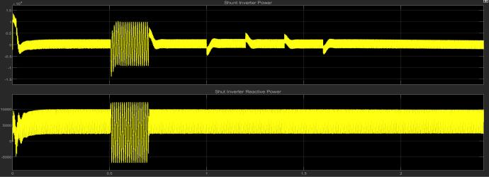
Analysis of Current Waveforms and Harmonic Mitigation: We evaluate the harmonic reduction performanceoftheshuntconverter.Bothbeforeandafter turningontheshuntconverter,thesimulationcalculatesthe total harmonic distortion of the current. The result of the simulation.TheTHDlevelsdramaticallydecreasewhilethe shunt converter is in operation, demonstrating that the UPQC successfully reduces harmonics brought on by nonlinear loads. The filtered current waveform's sinusoidal shapeatteststothepowerqualityenhancement.

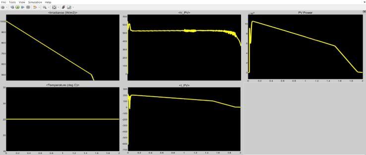
The Solar PV MPPT Efficiencyand Generation: Thepower production of the solar PV array is monitored in different sunlight situations. The simulation considers changes in irradiance to assess the system's performance with the MPPT controller. Simulation Result: The MPPT controller allows the PV system to run at its peak power even when solar irradiation fluctuates. The power output curve illustrateshowthesystemcandynamicallyadapttooptimize energygenerationefficiency.

International Research Journal of Engineering and Technology (IRJET) e-ISSN: 2395-0056
Volume: 12 Issue: 05 | May 2025 www.irjet.net p-ISSN: 2395-0072
Wind power generation: The wind is the source of the electricalenergy.thedifferentspeedsatdifferenttimes.The powerproducedinthePMSGisdeterminedbythatspeed.

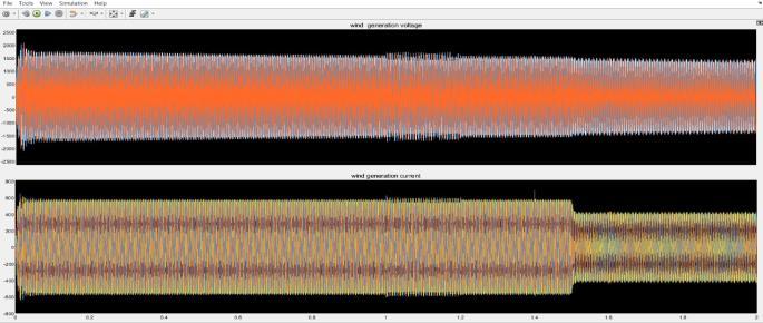
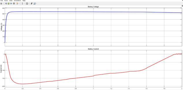
Energy Management and Battery Performance: The battery'sstateofchargeandenergyflowsaremonitoredina variety of circumstances, such as charging from excess photovoltaicenergy,dischargingduringperiodsoflowPV output, and serving as a backup during grid outages. Simulation Result. Through the maintenance of the SOC within a safe and practical range, such as 20–80%, the batteryefficientlysupportsthesystemduringtimesofhigh demand and grid outages. By regulating the charging and dischargingcyclestoavoidoverchargingordeepdischarge, theBMSefficientlymanagesenergy.
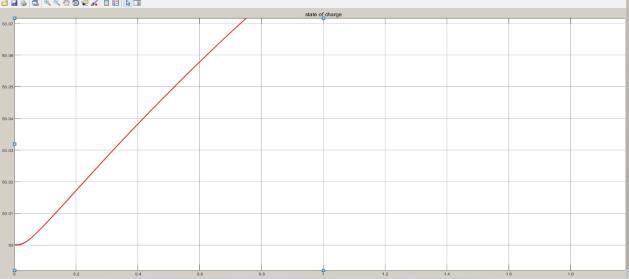

The system's overall performance: In network-related frameworks, the solar-powered PV system and batterycoordinatedUPQCsystemefficientlyhandlepowerquality issues. As the battery system charges or discharges as necessary to preserve stability, the UPQC's series compensator adjusts sags and swells during voltage fluctuations. Under non-linear load conditions, the shunt compensator filters harmonics, protecting sensitive equipment and ensuring clean power delivery. In imbalancedsituations,theUPQCbalancesthephasevoltages and guarantees consistent power distribution throughout the phases. The battery provides steady support under fluctuatingirradiationbystoringexcesssolarenergyduring high output and discharging during low PV production. Consequently, by maintaining steady voltage and power quality.

International Research Journal of Engineering and Technology (IRJET) e-ISSN: 2395-0056
Volume: 12 Issue: 05 | May 2025 www.irjet.net p-ISSN: 2395-0072
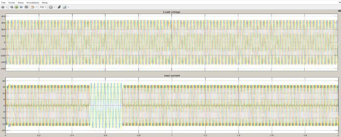

Incontemporaryenergysystems,thesuggestedmicrogridbasedUPQCsystemwithwind-drivenPMSG,DG,andasolar PV array offers a very practical way to improve power qualityandmaximizefuelefficiency.Thesystemeffectively reduces power quality problems such reactive power imbalances, harmonics, and voltage fluctuations by incorporatingaUPQC,guaranteeingsteadyandeffectivegrid operation. This results in lower carbon emissions and operatingcosts.Bydynamicallycontrollingpowersharing, the controller-based intelligent BMS makes sure that DG units only run when needed, reducing fuel waste and increasing system efficiency. Fuel consumption was optimizedbygivingrenewableenergysourcesprecedenceto DG units. Real-time power compensation and adaptive controltechniquesimprovegridstabilityandreliability.
1.C.WuandH.Nian,“Statorharmoniccurrentssuppression forDFIG basedonfeed-forwardregulatorunderdistorted gridvoltage,”IEEETrans.PowerElectron.,vol.33,no.2,pp. 1211-1224,Feb.2018.
2. P. Shah, I. Hussain, and B. Singh, “Single-stage SECS interfaced with grid using ISOGI-FLL-based control algorithm,”IEEETrans.Ind.Applica.,vol.55,no.1,pp.701711,Jan.-Feb.2019.
3.A.K.Singh,I.Hussain,andB.Singh,“Double-stagethreephase grid integrated solar PV system with fast zero attracting normalized least mean fourth based adaptive control,”IEEETrans.Ind.Electron.,vol.65,no.5,pp.39213931,May2018.
4.S.K.Tiwari,B.Singh,andP.K.Goel,“Designandcontrolof autonomouswind–solarsystemwithDFIGfeeding3-phase 4-wireloads,”IEEETrans.Ind.Applicate.,vol.54,no.2,pp. 1119-1127,March-April2018.
5.PuchalapalliandB.Singh,“AsingleinputvariableFLCfor DFIG based WPGS in standalone mode,” IEEE Trans. SustainableEnergy,vol.11,no.2,pp.595-607,April2020.
6.J.HussainandM.K.Mishra,“Adaptivemaximumpower pointtrackingcontrolalgorithmforwindenergyconversion systems,” IEEE Trans. Energy Convers., vol. 31, no. 2, pp. 697-705,June2016.
7.J.M.Carrasco,L.G.Franquelo,J.T.Bialasiewicz,E.Galván, R.CPortilloGuisado,M.M.Prats,J.I.León,andN.MorenoAlfonso,“Power-electronicsystemsforthegridintegration ofrenewableenergysourcesAsurvey”,IEEETransactions onindustrialelectronics,Vol.4,pp.1002-16,June2006.
8.Y.Chen,X.Zha,J.Wang,H.Liu,J.Sun,andH.Tang,“Unified powerqualityconditioner(UPQC):Thetheory,modelingand application”, In Power System Technology, Proceedings. Power Con International Conference on IEEE, Vol. 3, pp. 1329-33,2000.
9.E.Clarke,CircuitAnalysisofA-CPowerSystems,VolI –SymmetricalandRelatedComponents,JohnWileyandSons, 1943.
10. Villalva, M. G., Gozzoli, J. R., & Ruppert, E. (2009). "Comprehensive approach to modeling and simulation of photovoltaic arrays." IEEE Transactions on Power Electronics,24(5),1198-1208.
11. Wang, B., Blaabjerg, F., & Chen, Z. (2009). "Power electronicsforwindturbinesystems."IEEETransactionson IndustryApplications,25(4),964-976.
12. Kumar, M., & Gupta, R. (2019). "Microgrid energy management:Areviewofoperatingstrategies,optimization methods, and future trends." IEEE Access, 7, 101113101137.
13. Liserre, M., Blaabjerg, F., & Hansen, S. (2001). "Design and control of an LCL-filter-based three-phase active rectifier."IEEETransactionsonIndustryApplications,41(5), 1281-1291.
14.Mohanty,P.,Sharma,M.P.,&Ray,P.K.(2016)."Hybrid energy storage system integration for microgrid applications:Areview." JournalofEnergyStorage,6,116126.
15. He, J., & Balog, R. S. (2016). "Harmonic mitigation of powerelectronicsloadsusingpowerqualitycompensators: A review." IEEE Transactions on Industrial Electronics, 62(3),1227-1240.