
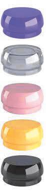
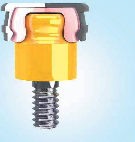
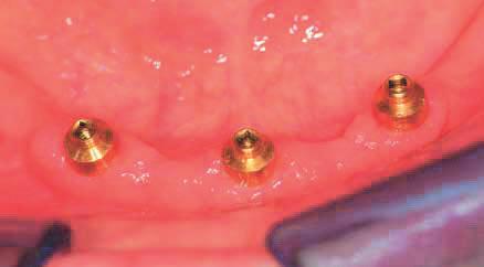
OT EQUATOR FOR IMPLANTS
Low Profile Titanium Abutment

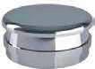
RETENTIVE CAPS
OT EQUATOR

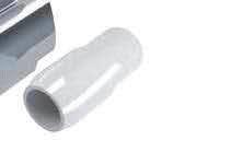
STAINLESS STEEL HOUSING
VIOLET CAP RIGID RETENTION (2.7Kg)
WHITE CAP STANDARD RETENTION (1.8Kg)
PINK CAP SOFT RETENTION (1.2Kg)
YELLOW CAP EXTRA-SOFT RETENTION (0.6Kg)
BLACK CAP PROCESSING


OT EQUATOR PROFILE TITANIUM + TIN ATTACHMENT
IMPRESSION TRANSFER (pick-up impression)
IMPRESSION TRANSFER (individual tray)


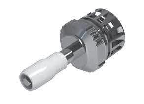

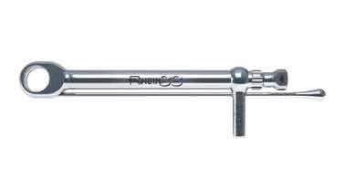
SQUARE SCREWDRIVER 1.25 MM + EQUATOR HOLDER for implant abutment usable with Ratchet torque control device
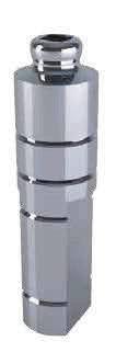
STAINLESS STEEL ANALOG FOR PLASTER MODEL


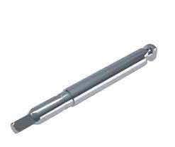

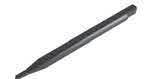
SQUARE DRIVER CONNECTOR 1.25mm for contra angle torque controller

INTERCHANGEABLE OT EQUATOR HOLDER
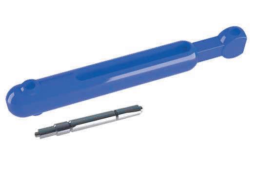


INSERTION TOOL FOR RETENTIVE CAPS Normal size and for “Seeger” Rings


RATCHET TORQUE CONTROL DEVICE For Sphero block - flex and Ot Equator 15/35Ncm Strenght - Max 50Ncm torque, suggested 25Ncm.
EXTRACTOR TOOL FOR RETENTIVE CAPS
The unique design and exceptionally low 2.1mm profile of the OT Equator 4 in 1 System provides exceptional stability and superior retention when compared with other attachment systems. Due to its lower radius, OT Equator is indicated to correct divergence up to 28 degrees between implants without affecting the functionally of the elastic nylon cap. Caps are available in a wide variety of retention levels. ATTENTION; Where implant divergence exceed the maximum 28 degrees, Sphero Block and Sphero Flex are recommended case plan options. See Sphero Block and Sphero Flex page 40-41

Technical Procedure
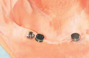
ATTACHING THE CAPS IN CLINIC

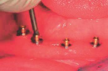


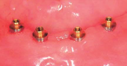
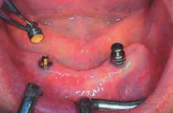
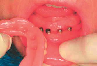
Select the OT Equator with the appropriate cuff height. Screw the OT Equator into the implant.


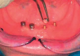
Place the protective disk over the OT Equator. Then, place the stainless steel housing with cap on the attachment.

Remove the prosthesis and verify that the positions of the attachments are correct.


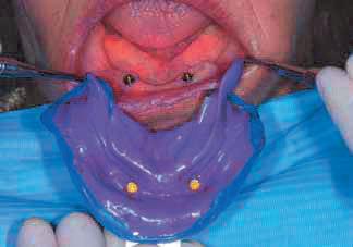
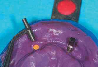
IMPRESSION TRANSFER
Place the implression coping on the OT Equator.


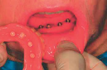
Verify the positioning of the prosthesis before bonding the stainless steel housing. On the prosthesis, fill the implant sites with a self curing resin and insert into the patient’s mouth.

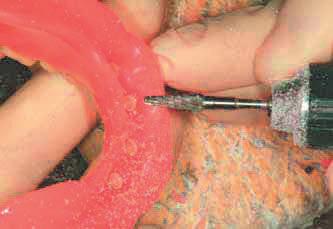

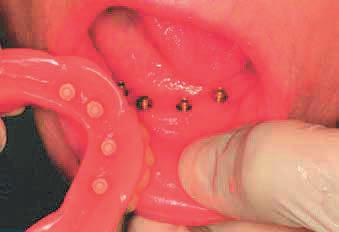
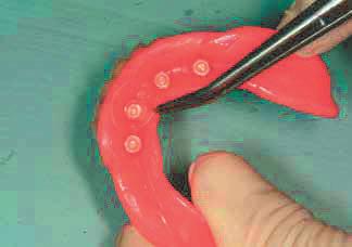
Remove the protective disks.Carefully trim away the excess resin.The completed prosthesis.
The impression coping picked up in the impression.

Insert the analog into the impression coping and pour the master model.


BUILD UP THE FRAME DIRECTLY ON MASTER MODEL

Master model with analog in position.


Master model with OT Equator analog in position. Also pictured is the stainless steel housing with black processing cap.


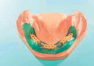


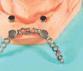
Finish the metal frame and verify the position on the model.


Apply a thin layer (.5mm) of wax on the model. Fill the undercuts on the stainless steel housing with wax and attach the connectors.

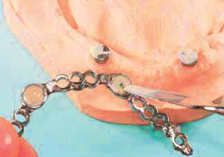

Use composite to bond the stainless steel housing to the frame.

Attach the parts using a castable resin. Be sure to cover the stainless steel housing.


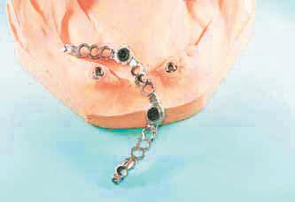

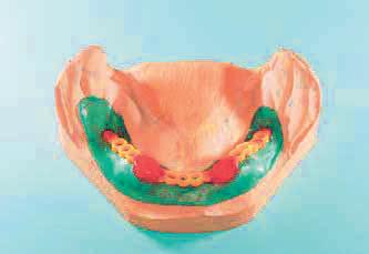
The metal frame with stainless steel housings bonded in place.


Add sprues to the framework and remove it from the model. Be sure that the stainless steel housing does not remain inside.


The finished prosthesis on metal frame. After processing, the black caps are replaced with pink caps.