1
CYLINDER SIZING AND SPEED CONTROL Cylinder sizing for thrust
A C T U A TOR S
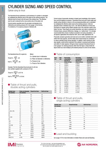
The theoretical thrust (outstroke) or pull (instroke) of a cylinder is calculated by multiplying the effective area of the piston by the working pressure. The effective area for thrust is the full area of the cylinder bore. The effective area for pull is reduced by the cross section area of the piston rod. Current practice specifies bore (D) and piston rod diameter (d) in millimetres and working pressure (P) in bar gauge. In the formula, P is divided by 10 to express pressure in Newtons (N)
d
Correct sizing of pneumatic actuators is based upon knowledge of the required force and the applied air pressure. Theoretical thrust and pull of both single and double acting cylinders is shown on the accompanying tables and is calculated by multiplying the effective piston area by the working pressure. Units are generally shown in Newtons (kg x 9,81 = N). Note the difference in thrust and pull figures on double acting rodded cylinders due to the reduction made by the piston rod area. These figures are purely theoretical, and make no allowance for frictional losses, pressure differences, leakage, or a ‘safety factor’. It is strongly recommended that a factor of safety be included in all sizing calculations – on all dynamic applications this should be 50%, and on static applications 5%. Pneumatic actuators generally work best and can be better controlled when well within their load capacity, and this safety factor should always be considered to reduce potential issues during operation. In addition, when working at ultra slow speeds, control will be improved if the cylinder is oversized and working well within it’s total capacity. All figures shown represent theoretical thrust at 6 bar (gauge). For working pressures other than this figure, simply divide the figure shown by 6 and multiply by the desired pressure to arrive at new values.
D
The theoretical force (F) is given by
Where
πD2P Thrust F= =N 40 2 2 π(D -d )P Pull F= =N 40
D = Cylinder bore in millimetres d = Piston rod diameter in millimetres
Table of consumption
18
Online at www.imi-precision.com
4
Push stroke consumption dm3/mm of stroke at 6 bar 0,00054
Pull stroke consumption dm3/mm of stroke at 6 bar 0,00046
Combined consumption dm3/mm of stroke/cycle 0,00100
6
0,00079
0,00065
0,00144
6
0,00141
0,00121
0,00262
20
8
0,00220
0,00185
0,00405
25
10
0,00344
0,00289
0,00633
32
12
0,00563
0,00484
0,01047
40
16
0,00880
0,00739
0,01619
50
20
0,01374
0,01155
0,02529
63
20
0,02182
0,01962
0,04144
80
25
0,03519
0,03175
0,06694
100
25
0,05498
0,05154
0,10652
125
32
0,08590
0,08027
0,16617
160
40
0,14074
0,13195
0,27269
200
40
0,21991
0,21112
0,43103
250
50
0,34361
0,32987
0,67348
Bore mm
Rod mm
10 12 16
P = Pressure in bar F = Thrust or Pull in Newtons
Example: Find the theoretical thrust and pull of a 50 mm bore cylinder supplied with a pressure of 8 bar π502.8 Thrust F= =1571 N 40 π(502-202).8 Pull F= =1319 N 40
able of thrust and pulls, T double acting cylinders Cylinder bore mm (inches)
Piston rod diameter Thrust N at 6 bar mm (inches)
Pull N at 6 bar
8
3
30
25
10
4
47
39
12
6
67
50
16
6
120
103
20
8
188
158
25
10
294
246
32
12
482
414
40
16
753
633
44,45 (1,75)
16
931
810
50
20
1178
989
63
20
1870
1681
76,2 (3)
25
2736
2441
80
25
3015
2721
100
25
4712
4418
125
32
7363
6881
152,4 (6)
(1,5)
10944
10260
160
40
12063
11309
200
40
18849
18095
250
50
29452
28274
304,8 (12)
(2,25)
43779
42240
320
63
48254
46384
355,6 (14)
(2,25)
59588
58049
able of thrust and pulls, T single acting cylinders Cylinder bore mm (inches)
Thrust N at 6 bar
Pull N at 6 bar
10
37
3
12
59
4 7
16
105
20
165
14
25
258
23
32
438
27
40
699
39
50
1102
48
63
1760
67
80
2892
86
100
4583
99
Load and buckling Go to page 147 for more information on Golden Rules and Load and Buckling.
For further information, visit www.imi-precision.com and use the new improved search function. If you cannot see the option you require please contact us.