https://doi.org/10.22214/ijraset.2023.49577

11 III
2023
March
ISSN: 2321-9653; IC Value: 45.98; SJ Impact Factor: 7.538

Volume 11 Issue III Mar 2023- Available at www.ijraset.com

https://doi.org/10.22214/ijraset.2023.49577
ISSN: 2321-9653; IC Value: 45.98; SJ Impact Factor: 7.538
Volume 11 Issue III Mar 2023- Available at www.ijraset.com
Mrs. T. Bhargavi1, Dr. S. Sivaganesan2
1PG scholar in the Dept. of Electrical & Electronics Engineering, in Holy Mary Institute of Technology & Science, Bogaram (V), Medchal District, Hyderabad, India.
2Professor in the Dept. of Electrical & Electronics Engineering, in Holy Mary Institute of Technology & Science, Bogaram (V), Medchal District, Hyderabad, India.
Abstract: A control strategy for power flow management of a grid-connected hybrid photovoltaic (PV)–wind-battery- based system with an efficient multi-input transformer-coupled bidirectional dc–dc converter is presented. The proposed system aims to satisfy the load demand, manage the power flow from different sources, inject the surplus power into the grid, and charge the battery from the grid as and when required. A transformer-coupled boost half-bridge converter is used to harness power from wind, while a bidirectional buck– boost converter is used to harness power from PV along with battery charging/discharging control. A single-phase full-bridge bidirectional converter is used for feeding ac loads and interaction with the grid. The proposed converter architecture has reduced number of power conversion stages with less component count and reduced losses compared with existing grid-connected hybrid systems. This improves the efficiency and the reliability of the system. Simulation results obtained using MATLAB/Simulink show the performance of the proposed control strategy for power flow management under various modes of operation. The effectiveness of the topology and the efficacy of the proposed control strategy are validated through detailed experimental studies to demonstrate the capability of the system operation in different modes.
Keywords: Grid, Photovoltaic (PV), wind, battery, bidirectional converter.
Rapid depletion of fossil fuel reserves, ever increasing energy demand and concerns over climate change motivate power generation from renewable energy sources. Solar photovoltaic (PV) and wind have emerged as popular energy sources due to their ecofriendly nature and cost effectiveness. However, these sources are intermittent in nature. Hence, it is a challenge to supply stable and continuous power using these sources. This can be addressed by efficiently integrating with energy storage elements. The interesting complementary behavior of solar insolation and wind velocity pattern coupled with the above-mentioned advantages has led to the research on their integration resulting in the hybrid PV–wind systems. For achieving the integration of multiple renewable sources, the traditional approach involves using dedicated single-input converters one for each source, which are connected to a common dcbus [1]–[15]. However, these converters are not effectively utilized, due to the intermittent nature of the renewable sources. In addition, there are multiple power conversion stages which reduce the efficiency of the system.
A significant amount of the literature exists on the integration of solar and wind energy, as a hybrid energy generation system mainly focuses on its sizing and optimization [7], [8]. In [7], the sizing of generators in a hybrid system is investigated. In this system, the sources and storage are interfaced at the dc-link through their dedicated converters. Other contributions are made on their modeling aspects and control techniques for a stand-alone hybrid energy system in [9]–[15]. Dynamic performance of a standalone hybrid PV–wind system with battery storage is analyzed in [9]. In [14], a passivity/sliding mode control is presented which controls the operation of wind energy system to complement the solar energy generating system. Not many attempts are made to optimize the circuit configuration of these systems that could reduce the cost and increase the efficiency and reliability. In [16]–[19], integrated converters for PV and wind energy systems are presented. PV–wind hybrid system, proposed in [16], has a simple power topology, but it is suitable for stand-alone applications. An integrated four-port topology based on hybrid PV–wind system is proposed in [18]. However, despite simple topology, the control scheme used is complex. In [19], to feed the dc loads, a low capacity multiport converter for a hybrid system is presented.
ISSN: 2321-9653; IC Value: 45.98; SJ Impact Factor: 7.538
Volume 11 Issue III Mar 2023- Available at www.ijraset.com
Hybrid PV–wind-based generation of electricity and its interface with the power grid are the important research areas. Chen et al. [20], [21] have proposed a multi-input hybrid PV–wind power generation system which has a buck/buck– boost-fused multi-input dc–dc converter and a full-bridge dc–ac inverter. This system is mainly focused on improving the dc-link voltage regulation. In the six-arm converter topology proposed in [22], the outputs of a PV array and wind generators are fed to a boost converter to match the dc-bus voltage. The steady-state performance of a grid-connected hybrid PV and wind system with battery storage is analyzed in [4]. This paper focuses on system engineering, such as energy production, system reliability, unit sizing, and cost analysis. In [5], a hybrid PV–wind system along with a battery is presented, in which both sources are connected to a common dc-bus through individual power converters. In addition, the dc-bus is connected to the utility grid through an inverter. The use of multi-input converter for hybrid power systems is attracting increasing attention because of reduced component count, enhanced power density, compactness, and centralized control. Due to these advantages, many topologies are proposed, and they can be classified into three groups, namely, nonisolated, fully isolated, and partially isolated multiport topologies. All the power ports in nonisolated multiport topologies share a common ground. To derive the multiport dc–dc converters, a series or parallel configuration is employed in the input side [23]–[27]. Some components can be shared by each input port. However, a time-sharing control scheme couples each input port, and the flexibility of the energy delivery is limited. The series or parallel configuration can be extended at the output to derive multiport dc–dc converters [28]. However, the power components cannot be shared. All the topologies in nonisolated multiport are mostly combinations of the basic topology units, such as the buck, the boost, the buck–boost, or the bidirectional buck/boost topology unit. These timesharing- based multiport topologies promise low cost and easy implementation. However, a common limitation is that power from multiple inputs cannot be simultaneously transferred to the load. Furthermore, matching wide voltage ranges will be difficult in these circuits. This made the researchers to prefer isolated multiport converters compared with nonisolated multiport dc–dc converters. The magnetic coupling approach is used to derive a multiport converter [29]–[32], where the multiwinding transformer is employed to combine each terminal. In fully isolated multiport dc–dc converters, the half-bridge, full-bridge, and hybridstructure- based multiport dc–dc converters with a magnetic coupling solution can be derived for different applications, power, voltage, and current levels. The snubber capacitors and transformer leakage inductance are employed to achieve softswitching by adjusting the phaseshift angle. However, the circuit layout is complex, and the only sharing component is the multiwinding transformer. Therefore, the disadvantage of time-sharing control to couple input port is overcome. Here, among multiple inputs, each input has its own power components which increases the component count. In addition, the design of multiwinding transformer is an involved process. In order to address the above-mentioned limitations, partially isolated multiport topologies [33]–[39] are becoming increasingly attractive. In these topologies, some power ports share a common ground, and these power ports are isolated from the remaining for matching port voltage levels.
The effort to obtain ever-increasing power density of switched-mode power supplies has been limited by the size of passive components. Operation at higher frequencies considerably reduces the size of passive components, such as transformers and filters; however, switching losses have hindered high-frequency operation. To reduce switching losses and allow high-frequency operation, resonant switching and soft-switching techniques have been developed [1-5] . The resonant switching method processes power in a sinusoidal manner by utilizing the resonance during the entire switching period. Generally, the output voltage is regulated by variable frequency control and the current or voltage waveform in the resonant network has a sinusoidal shape. Meanwhile, softswitching techniques utilize the resonance operation only during the switching transition to soften the switching characteristics of the devices.
When the switching transition is over, the converter reverts to Pulse-Width-Modulation (PWM) mode. Since resonant operation only occurs during the switching transition, the parameters of resonant components are not as critical as in a resonant converter. Moreover, the switching frequency is fixed and easily synchronized to the other power stages to minimize EMI. Among various kinds of soft-switching converters, the asymmetric PWM half-bridge converter has drawn attention due to its simplicity and inherent zero voltage switching (ZVS) capability. Figure 1 and 2 show the basic circuit and typical operation waveforms of the asymmetric PWM half-bridge converter.
This converter has several advantages over other soft-switching topologies: low MOSFET voltage and current stress, small output capacitor and inductor, minimum component count, and simple control.
ISSN: 2321-9653; IC Value: 45.98; SJ Impact Factor: 7.538
Volume 11 Issue III Mar 2023- Available at www.ijraset.com
Presents design considerations of an asymmetric PWM half-bridge converter. It includes designing the transformer and selecting the components. The step-by-step design procedure explained with a design example will help engineers design an asymmetric PWM half-bridge converter.
In general, the asymmetric PWM half-bridge converter consists of three stages, as shown in Figure a square wave generator, energy transfer network, and rectifier network.
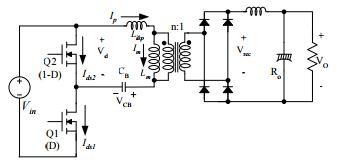
The square wave generator produces a square wave voltage (Vd) by driving switches Q1 and Q2 complementarily. In order words, the lower and upper MOSFETs duty cycles should be D and 1-D, respectively. A small dead time is usually introduced between the consecutive transitions.
The energy transfer network consists of a DC blocking capacitor and transformer. The energy transfer network removes the DC offset of the square wave voltage (Vd) using the DC blocking capacitor (CB), then transfers the pure AC square wave voltage to the secondary side through the transformer. The transformer primary-side current, Ip, lags the voltage applied to the transformer primary side due to the leakage inductance, which allows the MOSFETs to be turned on with zero voltage. As seen in Figure 7, after one of the switches has been turned off, Ip charges (or discharges) the MOSFET output capacitances and eventually swings the switch voltages from one input rail to the other (from Vin to ground or from ground to Vin). Then, Ip continues to flow through the antiparallel body diode. As long as the body diode conducts, the corresponding MOSFET can be turned on with zero voltage.
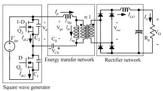
The rectifier network produces a DC voltage by rectifying the AC voltage with rectifier diodes and a low-pass LC filter. The rectifier network can be implemented as a full-wave bridge or center-tapped configuration. In steady-state analysis, the following assumptions are made:
The dead time is negligible since it is very small compared to the switching cycle.
The leakage inductance is much smaller than the magnetizing inductance.
The DC blocking capacitor, CB, is large enough to neglect the voltage ripple across CB.
The output filter inductor operates in continuous conduction mode.
All circuit elements are ideal and lossless.
The duty cycle for lower MOSFET, D, is limited below 50%.
The capacitors C1 and C2 include not only the internal output capacitance of MOSFETs, but also the external parasitic capacitances.
ISSN: 2321-9653; IC Value: 45.98; SJ Impact Factor: 7.538
Volume 11 Issue III Mar 2023- Available at www.ijraset.com
1) Mode I (to~t1): The lower switch (Q1) is conducting and a voltage of (Vin-VCB) is applied to the transformer primary side (Vpr). The transformer primary-side current (Ip) is the sum of the output inductor current referred to as the primary side (ILO/n) and the magnetizing current (IM). This mode is similar to the power transferring mode of a conventional half-bridge converter.
2) Mode II (t1~t2): The lower switch (Q1) is turned off at t1 and the primary side current, Ip, charges C1 and discharges C2. This mode continues until the primary-side voltage drops to zero (until C2 is discharged to VCB) at t2. Since the secondary side is connected to the primary side, C2 is discharged using the energy stored in the leakage inductance and output inductor.

ISSN: 2321-9653; IC Value: 45.98; SJ Impact Factor: 7.538
Volume 11 Issue III Mar 2023- Available at www.ijraset.com
3) Mode III (t2~t3): At t2, the transformer primaryside and secondary-side voltages become zero and the secondary side is decoupled from the primary side. Then, the output inductor current, ILO, begins to freewheel in the secondary side through the rectifiers while C2 continues to be discharged. Since the secondary-side inductor (Lo) is disconnected from the primary side, C2 is discharged using the energy stored in the leakage inductance only. After C2 is fully discharged, the body diode of Q2 begins conducting before t3.
4) Mode IV (t3~t4): The body diode of Q2 is conducting and the voltage across the switch Q2 is clamped at zero. By turning on Q2 while the body diode is conducting, zero voltage switching (ZVS) is achieved. During this mode, a voltage of -VCB is applied across the leakage inductance and the primary-side current (Ip) decreases. This mode continues until Ip, plus the magnetizing current (IM), becomes -ILO/n. During this mode, the transformer secondary-side voltage remains zero, which causes duty cycle losses of as much as: 4 3 1 2 o lk L s S in t t I L D T T n V D − = = ⋅⋅⋅ (7) where Ts is the switching period.
5) Mode V (t4~t5): The upper switch (Q2) is conducting and -VCB is applied to the transformer primary side (Vpr). The transformer primary-side current (Ip) is the sum of the output inductor current referred to as the primary side (-ILO/n) and the magnetizing current (IM). This mode is similar to the power transferring mode of a conventional half-bridge converter.
6) Mode VI (t5~t6): The upper switch (Q2) is turned off at t5 and the primary-side current Ip charges C2 and discharges C1. This mode continues until the primary-side voltage becomes zero (until C1 is discharged to Vin-VCB) at t6. Since the secondary side inductor (Lo) is connected to the primary side, C1 is discharged using the energy stored in the leakage inductance and output inductor.
7) Mode VII (t6~t7): At t6, the transformer primary side and secondary-side voltages become zero and the secondary side is decoupled from the primary side. Then, the output inductor current, ILO, begins to freewheel in the secondary side and C1 continues to be discharged. Since the secondary side is disconnected from the primary side, C1 is discharged using the energy stored in the leakage.
A grid-connected hybrid PV–wind-battery-based system consisting of four power sources (grid, PV, wind source, and battery), and three power sinks (grid, battery, and load) requires a control scheme for power flow management to balance the power flow among these sources. The control philosophy for power flow management of the multisource system is developed based on the power balance principle. In the stand-alone case, PV and wind source generate their corresponding MPP power, and load takes the required power. In this case, the power balance is achieved by charging the battery until it reaches its maximum charging current limit Ib max. Upon reaching this limit, to ensure power balance, one of the sources or both have to deviate from their MPP power based on the load demand. In the grid-connected system, both the sources always operate at their MPP. In the absence of both the sources, the power is drawn from the grid to charge the battery as and when required. The equation for the power balance of the system is given by
Vpv Ipv + Vw Iw = Vb Ib + Vg Ig.
From (9), it is evident that if there is a change in power extracted from either PV or wind source, the battery current can be regulated by controlling the grid current Ig. Hence, the control of a single-phase full-bridge bidirectional converter depends on the availability of grid, power from PV and wind sources, and battery charge status. Its control strategy is shown in Fig.

ISSN: 2321-9653; IC Value: 45.98; SJ Impact Factor: 7.538
Volume 11 Issue III Mar 2023- Available at www.ijraset.com
The peak value of the output voltage for a single-phase full-bridge inverter is

v = maVdc (4) and the dc-link voltage is
Vdc = n(Vpv + Vb). (5)
Hence, substituting for Vdc in (4) gives
To ensure the supply of uninterrupted power to critical loads, priority is given to charge the batteries. After reaching the maximum battery charging current limit Ib max, the surplus power from renewable sources is fed to the grid. In the absence of these sources, battery is charged from the grid loads while injecting excess power into the grid is proposed.
ISSN: 2321-9653; IC Value: 45.98; SJ Impact Factor: 7.538
Volume 11 Issue III Mar 2023- Available at www.ijraset.com
Thus, the proposed configuration and control scheme provide an elegant integration of PV and wind energy source. It has the following advantages.
1) The maximum power point (MPP) tracking of both the sources, battery charging control, and bidirectional power flow is accomplished with six controllable switches.
2) The voltage boosting capability is accomplished by connecting PV and battery in series which is further enhanced by a highfrequency step-up transformer.
3) The improved utilization factor of the power converter, since the use of dedicated converters for ensuring MPP operation of both the sources is eliminated.
4) Galvanic isolation between the input sources and the load.
5) The proposed controller can operate in different modes of a grid-connected scheme, ensuring proper operating mode selection and smooth transition between different possible operating modes.
6) Enhancement in the battery charging efficiency as a single converter is present in the battery-charging path from the PV source. The basic philosophy and preliminary study of a compact and low-cost multi-input transformer-coupled dc–dc converter capable of interfacing multiple sources for a stand-alone application is presented in [40]. In this paper, the integration of renewable sources to the grid, detailed analysis, exhaustive simulation, and experimental studies have now been included. This paper is organized as follows. In Section II, the power circuit configuration of the grid-connected hybrid PV–wind-battery system is described along with its analysis.
Detailed simulation studies are carried out on the MATLAB/Simulink platform, and the results obtained for various operating conditions are presented in this section. The values of parameters used in the model for simulation are listed in Table


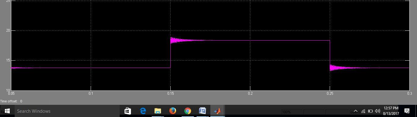
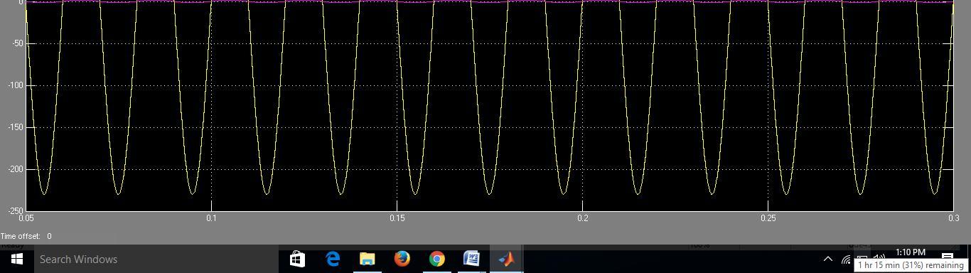
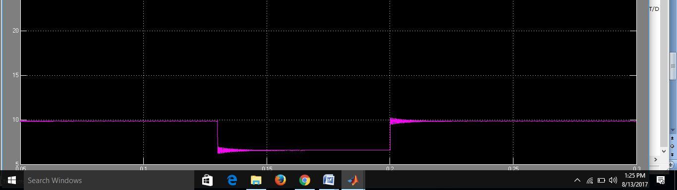
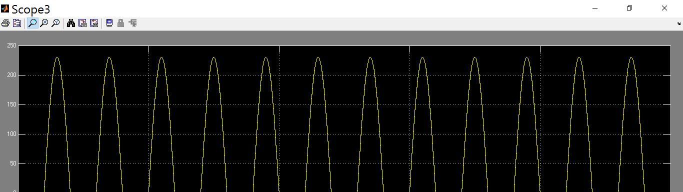
The steady-state response of the system during the MPPT mode of operation is shown in Fig. 4. The values for source-1 (PV source) is set at 35.4 V (Vmpp) and 14.8 A (Impp), and for source-2 (wind source) is set at 37.5 V (Vmpp) and 8 A (Impp). It can be seen that Vpv and Ipv of source-1, and Vw and Iw of source-2 attain set values required for MPP operation. The battery charged with the constant magnitude of current, and the remaining power is fed to the grid. The system response for step changes in the source-1 insolation level while operating in the MPPT mode is shown Both the sources are operating at MPPT and charging the battery with constant current and the remaining power is fed to the grid. At instant 2 s, the source-1 insolation level is increased. As a result, the source-1 power increases, and both the sources continue to operate at MPPT. Though the source-1 power has increased, the battery is still charged with the same magnitude of current, and power balance is achieved by increasing the power supplied to the grid. At instant 4 s, the insolation of source-1 is brought to the same level as before 2 s. The power supplied by source-1 decreases. Battery continues to get charged at the same magnitude of current, and power injected into the grid decreases. The same results are obtained for step changes in the source-2 wind speed level. These results are shown in Fig. The response of the system in the absence of source-1 is shown in Fig. Until time 2 s, both the sources are generating.
1) Case 1


ISSN: 2321-9653; IC Value: 45.98; SJ Impact Factor: 7.538


Volume 11 Issue III Mar 2023- Available at www.ijraset.com


ISSN: 2321-9653; IC Value: 45.98; SJ Impact Factor: 7.538

Volume 11 Issue III Mar 2023- Available at www.ijraset.com

ISSN: 2321-9653; IC Value: 45.98; SJ Impact Factor: 7.538
Volume 11 Issue III Mar 2023- Available at www.ijraset.com
A grid-connected hybrid PV–wind-battery-based power evacuation scheme for household application is proposed. The proposed hybrid system provides an elegant integration of PV and wind source to extract maximum energy from the two sources. It is realized by a novel multi-input transformer coupled bidirectional dc–dc converter followed by a conventional full-bridge inverter. A versatile control strategy which achieves a better utilization of PV, wind power, battery capacities without effecting life of battery, and power flow management in a grid-connected hybrid PV–wind-battery-based system feeding ac loads is presented. Detailed simulation studies are carried out to ascertain the viability of the scheme. The experimental results obtained are in close agreement with simulations and are supportive in demonstrating the capability of the system to operate either in grid feeding or in stand-alone modes. The proposed configuration is capable of supplying uninterruptible power to ac loads, and ensures the evacuation of surplus PV and wind power into the grid.
[1] F. Valenciaga and P. F. Puleston, “Supervisor control for a stand-alon hybrid generation system using wind and photovoltaic energy,” IEE Trans. Energy Convers., vol. 20, no. 2, pp. 398–405, Jun. 2005.
[2] C. Liu, K. T. Chau, and X. Zhang, “An efficient wind–photovoltaic hybrid generation system using doubly excited permanent-magnet brushles machine,” IEEE Trans. Ind. Electron., vol. 57, no. 3, pp. 831–839 Mar. 2010.
[3] W. Qi, J. Liu, X. Chen, and P. D. Christofides, “Supervisory predictive control of standalone wind/solar energy generation systems,” IEE Trans. Control Syst. Technol., vol. 19, no. 1, pp. 199–207, Jan. 2011.
[4] F. Giraud and Z. M. Salameh, “Steady-state performance of a gridconnected rooftop hybrid wind-photovoltaic power system with battery storage,” IEEE Trans. Energy Convers., vol. 16, no. 1, pp. 1–7, Mar. 2001.
[5] S.-K. Kim, J.-H. Jeon, C.-H. Cho, J.-B. Ahn, and S.-H. Kwon, “Dynamic modeling and control of a grid-connected hybrid generation system with versatile power transfer,” IEEE Trans. Ind. Electron., vol. 55, no. 4, pp. 1677–1688, Apr. 2008.
[6] M. Dali, J. Belhadj, and X. Roboam, “Hybrid solar–wind system with battery storage operating in grid-connected and standalone mode: Control and energy management Experimental investigation,” Energy, vol. 35, no. 6, pp. 2587–2595, Jun. 2010.
[7] W. D. Kellogg, M. H. Nehrir, G. Venkataramanan, and V. Gerez, “Generation unit sizing and cost analysis for stand-alone wind, photovoltaic, and hybrid wind/PV systems,” IEEE Trans. Energy Convers., vol. 13, no. 1, pp. 70–75, Mar. 1998.
[8] L. Xu, X. Ruan, C. Mao, B. Zhang, and Y. Luo, “An improved optimal sizing method for wind-solar-battery hybrid power system,” IEEE Trans. Sustain. Energy, vol. 4, no. 3, pp. 774–785, Jul. 2013.
[9] B. S. Borowy and Z. M. Salameh, “Dynamic response of a standalone wind energy conversion system with battery energy storage to a wind gust,” IEEE Trans Energy Convers., vol. 12, no. 1, pp. 73–78, Mar. 1997.
[10] S. Bae and A. Kwasinski, “Dynamic modeling and operation strategy for a microgrid with wind and photovoltaic resources,” IEEE Trans. Smart Grid, vol. 3, no. 4, pp. 1867–1876, Dec. 2012.
[11] C. W. Chen, C. Y. Liao, K. H. Chen, and Y. M. Chen, “Modeling and controller design of a semiisolated multiinput converter for a hybrid PV/wind power charger system,” IEEE Trans. Power Electron., vol. 30, no. 9, pp. 4843–4853, Sep. 2015.
[12] M. H. Nehrir, B. J. LaMeres, G. Venkataramanan, V. Gerez, and L. A. Alvarado, “An approach to evaluate the general performance of stand-alone wind/photovoltaic generating systems,” IEEE Trans. Energy Convers., vol. 15, no. 4, pp. 433–439, Dec. 2000.
[13] W. M. Lin, C. M. Hong, and C. H. Chen, “Neural-network-based MPPT control of a stand-alone hybrid power generation system,” IEEE Trans. Power Electron., vol. 26, no. 12, pp. 3571–3581, Dec. 2011.
[14] F. Valenciaga, P. F. Puleston, and P. E. Battaiotto, “Power control of a solar/wind generation system without wind measurement: A passivity/ sliding mode approach,” IEEE Trans. Energy Convers., vol. 18, no. 4, pp. 501–507, Dec. 2003.
[15] T. Hirose and H. Matsuo, “Standalone hybrid wind-solar power generation system applying dump power control without dump load,” IEEE Trans. Ind. Electron., vol. 59, no. 2, pp. 988–997, Feb. 2012.
[16] S. A. Daniel and N. Ammasaigounden, “A novel hybrid isolated generating system based on PV fed inverter-assisted wind-driven induction generators,” IEEE Trans. Energy Convers., vol. 19, no. 2, pp. 416–422, Jun. 2004.
[17] R. G. Wandhare and V. Agarwal, “Novel integration of a PV-wind energy system with enhanced efficiency,” IEEE Trans. Power Electron., vol. 30, no. 7, pp. 3638–3649, Jul. 2015.
[18] Z. Qian, O. Abdel-Rahman, and I. Batarseh, “An integrated four-port DC/DC converter for renewable energy applications,” IEEE Trans. Power Electron., vol. 25, no. 7, pp. 1877–1887, Jul. 2010.
ISSN: 2321-9653; IC Value: 45.98; SJ Impact Factor: 7.538
Volume 11 Issue III Mar 2023- Available at www.ijraset.com
Mrs T. Bhargavi received the Diploma in Mina Institute of Engineering And Technology For Women Miryalaguda, Nalgonda (Dt), Telangana, India. And received the B.Tech Degree in Mina Institute of Engineering And Technology For Women Miryalaguda, Nalgonda (Dt), Telangana. and studying M.Tech in Power Electronics in Holy Mary Institute of Technology And Science Bogaram (V), Medchal (Dt), Hyderabad, in the Department of Electrical And Electronics Engineering.

Dr. S. Sivaganesan received the B.E. in Electrical and Electronics Engineering from University of Madras, TN in2003and M.Tech.in Power Electronics & Drives from SASTRA University, TN in 2006 and the Ph.D. degree in Electrical Engineering from Vels University, Tamilnadu in 2017. He is currently A Professor of Dept. of Electrical & Electronics Engineering at Holy Mary Institute of Technology and Science, Hyderabad. His research interests include photovoltaic systems, renewable energy systems, power electronics, and control of power electronics interfaces.