6 minute read
International Journal for Research in Applied Science & Engineering Technology (IJRASET)

from Power Quality in the Hybrid Grid PV-Wind-Battery by the Multi-Input Transformer Couple Bidirectional
by IJRASET

ISSN: 2321-9653; IC Value: 45.98; SJ Impact Factor: 7.538
Volume 11 Issue III Mar 2023- Available at www.ijraset.com
Advertisement
1) Mode I (to~t1): The lower switch (Q1) is conducting and a voltage of (Vin-VCB) is applied to the transformer primary side (Vpr). The transformer primary-side current (Ip) is the sum of the output inductor current referred to as the primary side (ILO/n) and the magnetizing current (IM). This mode is similar to the power transferring mode of a conventional half-bridge converter.
2) Mode II (t1~t2): The lower switch (Q1) is turned off at t1 and the primary side current, Ip, charges C1 and discharges C2. This mode continues until the primary-side voltage drops to zero (until C2 is discharged to VCB) at t2. Since the secondary side is connected to the primary side, C2 is discharged using the energy stored in the leakage inductance and output inductor.

ISSN: 2321-9653; IC Value: 45.98; SJ Impact Factor: 7.538
Volume 11 Issue III Mar 2023- Available at www.ijraset.com
3) Mode III (t2~t3): At t2, the transformer primaryside and secondary-side voltages become zero and the secondary side is decoupled from the primary side. Then, the output inductor current, ILO, begins to freewheel in the secondary side through the rectifiers while C2 continues to be discharged. Since the secondary-side inductor (Lo) is disconnected from the primary side, C2 is discharged using the energy stored in the leakage inductance only. After C2 is fully discharged, the body diode of Q2 begins conducting before t3.
4) Mode IV (t3~t4): The body diode of Q2 is conducting and the voltage across the switch Q2 is clamped at zero. By turning on Q2 while the body diode is conducting, zero voltage switching (ZVS) is achieved. During this mode, a voltage of -VCB is applied across the leakage inductance and the primary-side current (Ip) decreases. This mode continues until Ip, plus the magnetizing current (IM), becomes -ILO/n. During this mode, the transformer secondary-side voltage remains zero, which causes duty cycle losses of as much as: 4 3 1 2 o lk L s S in t t I L D T T n V D − = = ⋅⋅⋅ (7) where Ts is the switching period.
5) Mode V (t4~t5): The upper switch (Q2) is conducting and -VCB is applied to the transformer primary side (Vpr). The transformer primary-side current (Ip) is the sum of the output inductor current referred to as the primary side (-ILO/n) and the magnetizing current (IM). This mode is similar to the power transferring mode of a conventional half-bridge converter.
6) Mode VI (t5~t6): The upper switch (Q2) is turned off at t5 and the primary-side current Ip charges C2 and discharges C1. This mode continues until the primary-side voltage becomes zero (until C1 is discharged to Vin-VCB) at t6. Since the secondary side inductor (Lo) is connected to the primary side, C1 is discharged using the energy stored in the leakage inductance and output inductor.
7) Mode VII (t6~t7): At t6, the transformer primary side and secondary-side voltages become zero and the secondary side is decoupled from the primary side. Then, the output inductor current, ILO, begins to freewheel in the secondary side and C1 continues to be discharged. Since the secondary side is disconnected from the primary side, C1 is discharged using the energy stored in the leakage.
III. PROPOSEDSYSTEM
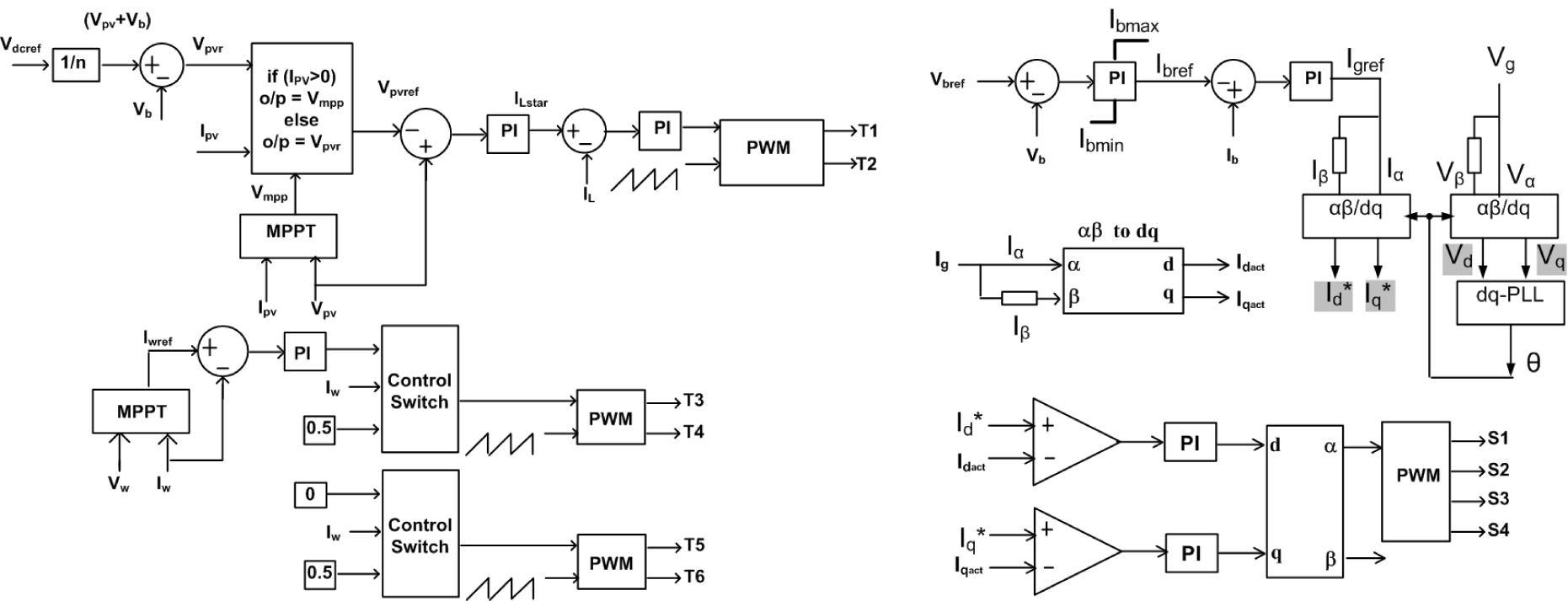
A grid-connected hybrid PV–wind-battery-based system consisting of four power sources (grid, PV, wind source, and battery), and three power sinks (grid, battery, and load) requires a control scheme for power flow management to balance the power flow among these sources. The control philosophy for power flow management of the multisource system is developed based on the power balance principle. In the stand-alone case, PV and wind source generate their corresponding MPP power, and load takes the required power. In this case, the power balance is achieved by charging the battery until it reaches its maximum charging current limit Ib max. Upon reaching this limit, to ensure power balance, one of the sources or both have to deviate from their MPP power based on the load demand. In the grid-connected system, both the sources always operate at their MPP. In the absence of both the sources, the power is drawn from the grid to charge the battery as and when required. The equation for the power balance of the system is given by
Vpv Ipv + Vw Iw = Vb Ib + Vg Ig.
From (9), it is evident that if there is a change in power extracted from either PV or wind source, the battery current can be regulated by controlling the grid current Ig. Hence, the control of a single-phase full-bridge bidirectional converter depends on the availability of grid, power from PV and wind sources, and battery charge status. Its control strategy is shown in Fig.
ISSN: 2321-9653; IC Value: 45.98; SJ Impact Factor: 7.538
Volume 11 Issue III Mar 2023- Available at www.ijraset.com
The peak value of the output voltage for a single-phase full-bridge inverter is v = maVdc (4) and the dc-link voltage is

Vdc = n(Vpv + Vb). (5)
Hence, substituting for Vdc in (4) gives
To ensure the supply of uninterrupted power to critical loads, priority is given to charge the batteries. After reaching the maximum battery charging current limit Ib max, the surplus power from renewable sources is fed to the grid. In the absence of these sources, battery is charged from the grid loads while injecting excess power into the grid is proposed.
ISSN: 2321-9653; IC Value: 45.98; SJ Impact Factor: 7.538
Volume 11 Issue III Mar 2023- Available at www.ijraset.com
Thus, the proposed configuration and control scheme provide an elegant integration of PV and wind energy source. It has the following advantages.
1) The maximum power point (MPP) tracking of both the sources, battery charging control, and bidirectional power flow is accomplished with six controllable switches.
2) The voltage boosting capability is accomplished by connecting PV and battery in series which is further enhanced by a highfrequency step-up transformer.
3) The improved utilization factor of the power converter, since the use of dedicated converters for ensuring MPP operation of both the sources is eliminated.
4) Galvanic isolation between the input sources and the load.
5) The proposed controller can operate in different modes of a grid-connected scheme, ensuring proper operating mode selection and smooth transition between different possible operating modes.
6) Enhancement in the battery charging efficiency as a single converter is present in the battery-charging path from the PV source. The basic philosophy and preliminary study of a compact and low-cost multi-input transformer-coupled dc–dc converter capable of interfacing multiple sources for a stand-alone application is presented in [40]. In this paper, the integration of renewable sources to the grid, detailed analysis, exhaustive simulation, and experimental studies have now been included. This paper is organized as follows. In Section II, the power circuit configuration of the grid-connected hybrid PV–wind-battery system is described along with its analysis.
IV.SIMULATIONRESULTS
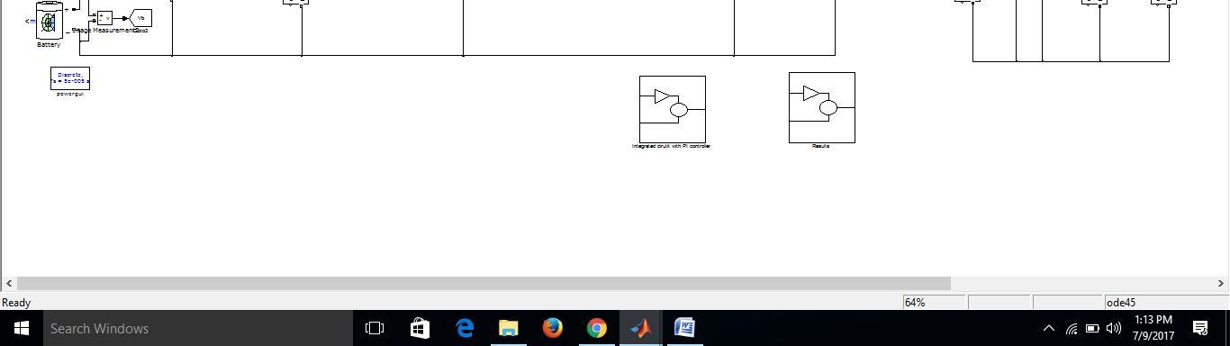
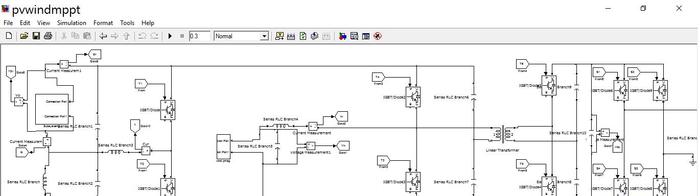
Detailed simulation studies are carried out on the MATLAB/Simulink platform, and the results obtained for various operating conditions are presented in this section. The values of parameters used in the model for simulation are listed in Table
A. Simulation Parameters
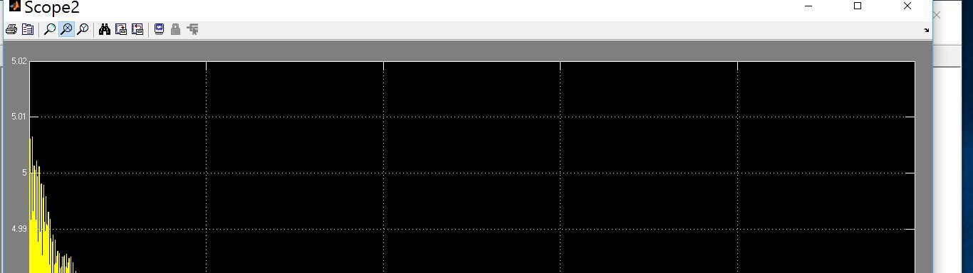
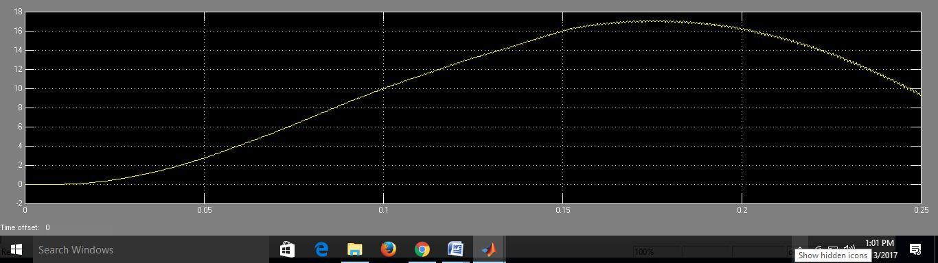
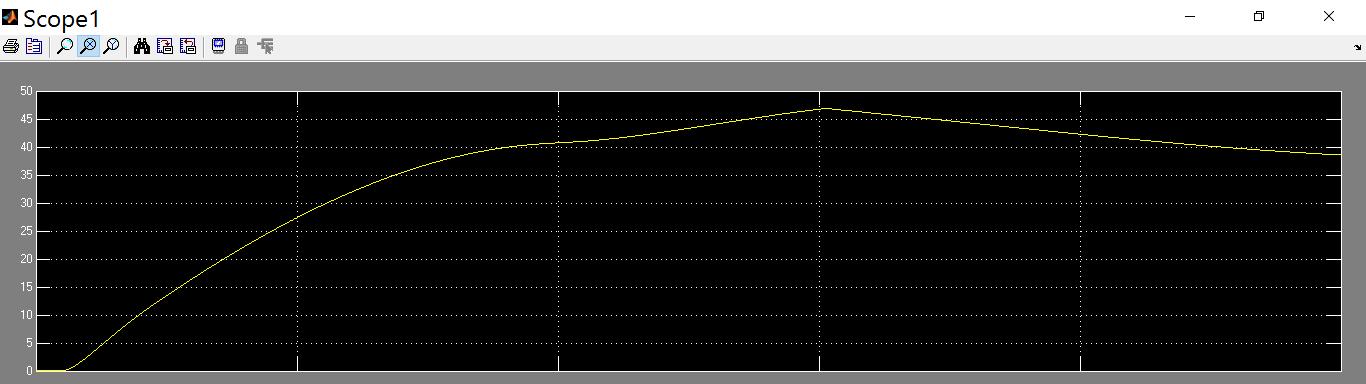
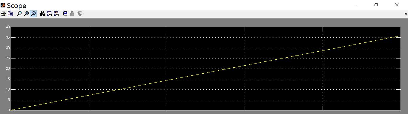
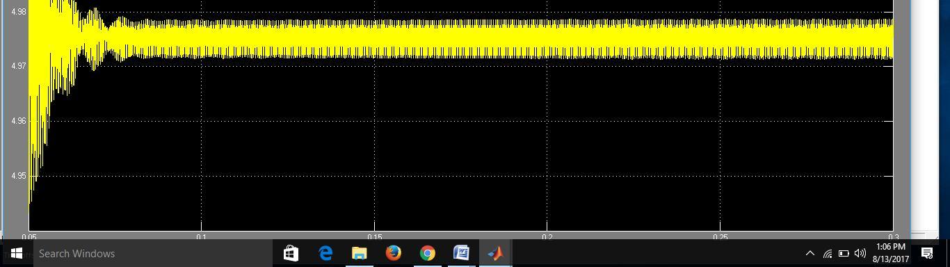
The steady-state response of the system during the MPPT mode of operation is shown in Fig. 4. The values for source-1 (PV source) is set at 35.4 V (Vmpp) and 14.8 A (Impp), and for source-2 (wind source) is set at 37.5 V (Vmpp) and 8 A (Impp). It can be seen that Vpv and Ipv of source-1, and Vw and Iw of source-2 attain set values required for MPP operation. The battery charged with the constant magnitude of current, and the remaining power is fed to the grid. The system response for step changes in the source-1 insolation level while operating in the MPPT mode is shown Both the sources are operating at MPPT and charging the battery with constant current and the remaining power is fed to the grid. At instant 2 s, the source-1 insolation level is increased. As a result, the source-1 power increases, and both the sources continue to operate at MPPT. Though the source-1 power has increased, the battery is still charged with the same magnitude of current, and power balance is achieved by increasing the power supplied to the grid. At instant 4 s, the insolation of source-1 is brought to the same level as before 2 s. The power supplied by source-1 decreases. Battery continues to get charged at the same magnitude of current, and power injected into the grid decreases. The same results are obtained for step changes in the source-2 wind speed level. These results are shown in Fig. The response of the system in the absence of source-1 is shown in Fig. Until time 2 s, both the sources are generating.
1) Case 1
International Journal for Research in Applied Science & Engineering Technology (IJRASET)

ISSN: 2321-9653; IC Value: 45.98; SJ Impact Factor: 7.538
Volume 11 Issue III Mar 2023- Available at www.ijraset.com

International Journal for Research in Applied Science & Engineering Technology (IJRASET)
ISSN: 2321-9653; IC Value: 45.98; SJ Impact Factor: 7.538
Volume 11 Issue III Mar 2023- Available at www.ijraset.com