
A Study On Manufacturing Of Flange Joint UsedInTransportationVehicle
OPEN ACCESS
Manuscript ID:
AG-2023-1005
Volume: 2
Issue: 1
Month: January
Year: 2023
ISSN: 2583-7117
Published: 15.01.2023
Citation:
Harsh Kumar Sharma. “A Study On Manufacturing Of Flange Joint Used In Transportation Vehicle” International Journal of Innovations In Science Engineering And Management, vol. 2, no. 1, 2023, pp. 01

05
This work is licensed under a Creative Commons Attribution-ShareAlike 4.0 International License
Harsh Kumar Sharma Research Scholar, Department of Mechanical Engineering, SIRTE, BhopalAbstract
Flange and flange connecting it to a commercial vehicle are processed in this investigation. Assemblies of Companion Flanges and Universal Drive shafts are also available. When the flange was brought in use in the commercial vehicles, it was seen that because if heavy friction, the part is deteriorating. To prevent this issue, a design was made which was further manufactured for accomplishing the goals of this study. When the product was ready, it was tested on CMM machine to find any type of error between the designed and manufactured product. The outcome obtained from the CMM machine showed a very small percentage of error. The new manufactured product had comparatively less amount of friction loss.
Keyword: Companion Flange; Drive shaft; Lath machine; Universal drive shaft, Industrial Manufacturing
Introduction
In a vehicle with rear-wheel drive, the engine's output is sent to the differential via a drive shaft. Since “the bending natural frequency of a shaft is inversely proportional to the square of the beam length and proportionate to the square root of the specific modulus”, the driving shaft is often made in two parts to raise the fundamental bending natural frequency. It is thus preferable to utilise a one-piece stainless steel drive shaft for this application, which is why stainless steel is the material of choice. As torque carriers, drive shafts experience torsional and shear stress equal to the difference between input torque and output torque. As a result, they must be capable of withstanding the pressure. Individual companion flanges or whole assemblies with universal drive shafts are available. For adequate torque transmission, a flanged yoke may be connected to another form of connection.
In “front-wheel drive, four-wheel drive, and the previously described frontengine rear-wheel drive systems”, drive shafts are employed differently. Other vehicles, such as motorbikes, locomotives, and maritime vessels, also use drive shafts. Drive shafts for a typical front engine, rear wheel drive vehicle are shown below (some cars have the transmission at the back).
Flange Joint
A pipeline system's components, such as pipes, valves, pumps, and other equipment, are linked together using flanges. Cleaning, inspecting, and modifying are all made much easier as a result. Most flanges are attached with screws or by welding. To create a tight seal, two flanges are bolted together and a gasket is sandwiched in between.
Flange ASME B16.5 comes in a variety of sizes. Welding Neck flange NPS 6, Class 150, Schedule 40 ASME B16.5 is referred to as such in Japan, Canada, and Australia.
It is possible to block or connect other components such as valves, nozzles, and special items using a pipe flange which is a disc-shaped piping component. After welding, piping flanges are the most popular as joining methods. Wherever, any dismantling of components is required for maintenance, inspection, replacement, or operational purposes piping flanged joints are preferred. Pipe flanges use bolts and gasket in between to ensure leakage-free piping joints. Piping flanges are selected based on pressuretemperature rating and pipe class following ASME B 16.5 or ASME B 16.47 standard. However, custom made pipe flanges can be manufactured but not preferred in industries. Piping flanges are the best alternative to welding or threading and manufactured by forging.
The most used flange types ASME B16.5 are: “Welding Neck, Slip On, Socket Weld, Lap Joint, Threaded and Blind flange”.
Process Flow Diagram
Diagrams describing the interactions between main plant components are shown in a Process Flow Diagram (PFD). Though its techniques are commonly applied to other processes as well, chemical engineering and process engineering are the most common fields in which it is used. To record a process, refine a process, or model a new one, it's utilised. If you want to name it anything else, you may call it anything from Process Flow Chart to Flow-sheet to Macro-flowchart to Top-down flowchart to Piping and Instrument Diagram to System Diagram, depending on what you want to call it and what it is used for. They represent a process using a set of symbols and notations. From crude, hand-drawn scribble to professional-looking, expanding detail diagrams, the symbols and diagrams vary in various parts of the world.
Objectives of the Study
• Analysis of problems in manufacturing process(s).
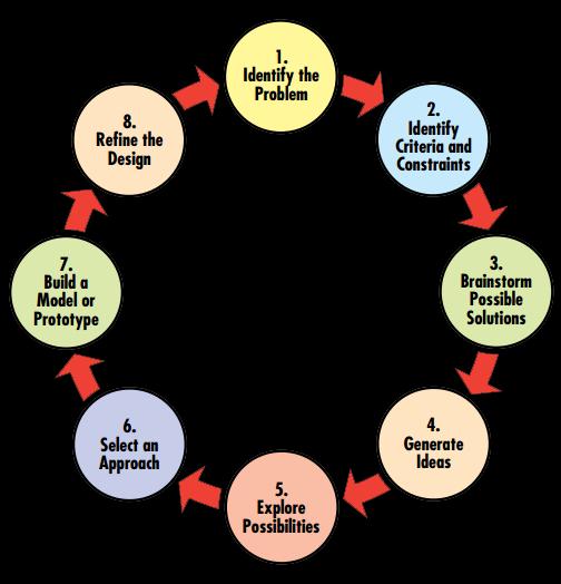
• The Design will be optimized as per analysis for DFM.
• To achieve the reduction in the non-conformance of final output.
• The jigs and fixtures will be introduced for quality improvement.
• Establishing new/advanced methods for measurement of parts.
• Creating Standard operation procedures for workstations and checking procedures.
• Better productivity will be achieved by reduction on rejection rate.
Literature Review
(Karaoǧlu and Sefa Kuralay, 2002) [1] By using the finite element method (FEM), a vehicle chassis with riveted joints was studied for stress. Side member thickness, connection plate thickness and connection plate length were altered to reduce stress around the riveted junction of the chassis frame.. The strains on the side member may be decreased by increasing the thickness of the side member locally, according to computer simulations. If changing the thickness isn't an option, expanding the length of the connectingplatecanbe. Avehicle'sstaticanddynamicloads are the same for everybody. Inertia forces caused by driving on uneven roads contribute to dynamic loads. Because the total weight of the chassis frame rises with increasing thickness, it is necessary to keep in mind.
(Kirkemo, 2002) [2] A wide variety of flange joints for high-pressure applications in industrial piping, pressure vessels, pipes, risers, and related equipment have been utilised widely with self seating and pressure actuated seal rings. Compact flange joints are often lighter and smaller, with smaller bolts, than regular gasketed flange joints of the same rating. To build small flange joints that can withstand pressure and external stresses, this document gives all the essential information. Also included in this document are instructions on how to design the seal ring, flange and bolts. Weld neck flanges with a homogeneous hub thickness are thoroughly examined.
(Sivakandhan and Prabhu, 2011) [3] Composite drive shafts for power transmission have been studied and optimised in this study. E-glass/epoxy and high modulus carbon/epoxy composites are used to make a one-piece composite drive shaft for automobiles. An ansys-based
method for optimising the design of composite drive shafts is discussed here. As a result of the constraints imposed by torque transmission, the weight ofa shaft must be minimised by employing ansys. Torsion strength, torsion buckling, and natural frequencyof bending are the primaryconsiderations. The draught shaft is designed in such a way that it is lightest and most cost-effective while yet meeting the aforementioned load criteria. Optimal laminated plate and shell designs exposed to buckling stresses and fundamental natural frequencies wereevaluated.Forsymmetricangle-ply shells of uniform thickness, methods were suggested to determine the best ply angle variation across the thickness.
(Abel et al., 2012) [4] “Mechatronic shifting simulation of automated commercial vehicle trans- missions” is utilised in Daimler's truck engineering divisions for optimization and development today. To demonstrate new functional mock-up interfaces in the ITEA2 project Modelisar, this application was used in conjunction with ITI GmbH and SIM-PACK AG (FMI). Models from a variety of different tools may be used to create the overall system for the mechanical shifting simulation by using these common interfaces. It was possible to transfer control modules from MATLAB/Simulink to a “SimulationX powertrain model using FMI for Model Exchange”, and then from the SimulationX 1D-multiphysics powertrain model to a multibody vehicle model in SIMPACK via this method.
(Zulfadhli Bin and Zaki, 2012) [5] Transaxles are a standard feature on all cars, at least those with rear-wheel drive and a front-engine layout. If the weight reduction of the drive shaft can be accomplished without an increase in cost and a drop in quality and dependability, this is a much desired aim. Composite drive shafts may be made lighter by increasing the first natural frequency and decreasing the bending stresses of the shaft utilising varied stacking sequence. This is doable. The transmission of torque and torsional buckling capabilities are also improved by performing the same thing. “High Strength Carbon drive shafts” are being used in lieu of traditional steel drive shafts in a car. In order to reduce vehicle weight while maintaining the same level of quality and dependability, the automotive industry is turning to composite material technologies for structural component fabrication.
(Sagar R Dharmadhikari, Sachin G Mahakalkar, Jayant P Giri, 2013) [6] The focus of this research is on the evaluation of drive shaft optimization using ANSYS and the Genetic Algorithm. For the drive shaft, using a composite material rather than traditional steel gives designers more flexibility in their designs because of the material's higher specific stiffness and strength. The drive shaft is the most important part of an automobile's drive system. Many drawbacks, such as poor specific stiffness and strength, come with using standard steel in the manufacture of drive shafts. If the design variables are not continuous, these approaches are not applicable. Structural engineering optimization, on the other hand, relies heavily on the use of discrete design factors. Constraints on building and manufacturing techniques have led to a lack of standard components.
Research Methodology
Steps of working
• Problemidentified byusing root cause analysis.
• Collect raw material for manufacturing process
• Outer Diameter & Face clean cut will be occurred in the companion flange on Lath Machine
• CNC machining
• Hardening process by using induction hardening.
• Flange spline is created by using Broaching operation
• VMC machine for maintaining the PCD
• Plunge Grinding
• Inspection report of part
Collecting raw material
First of all for manufacturing companion flange, Raw material is selected as from different type of materials. Different tests were performed on raw material for better strength and better durability of companion flange. [7] [8]Different dimensions are considered and material grade report is an important aspect that was looked according to report given by the raw material supplier. And after that it was tested in lab for confirming the grade and other parameters to choose the final material for next process. [9] [10] [11]

