The only publication worldwide dedicated to Industrial Ethernet Networking and the IIoT. Visit iebmedia.com for latest updates.
New website offers deepest, richest archive of Industrial Ethernet and IIoT content on the web.
View and/or download latest issue of Industrial Ethernet Book and past issues.
Search our database for in-depth technical articles on industrial networking.
Learn what's trending from 5G and TSN, to Single Pair Ethernet and more.
Keep up-to-date with new product introductions and industry news.
GET CONNECTED…
Technology focus: connectivity
The May/June 2025 issue of the Industrial Ethernet Book provides an in-depth into two issues that are helping to define the future of industrial networking: Single Pair Ethernet (SPE) and its companion, Ethernet APL, for process control networks along with a progress report on "State of Industrial Connectivity".
Our cover story in this issue, "Single Pair Ethernet and Ethernet APL for IIoT solutions" starts on page 6, and provides insights from industry leaders on the technologies that will make a difference.
The long-term potential is for Single Pair Ethernet and Ethernet APL to serve as the network infrastructure for the Industrial IoT, and the next generation communication architecture for automation. Originally developed for the automotive industry, now the promise is nothing less than a continuous connection from sensors to the cloud.
According to Dr. Al Beydoun, ODVA President and Executive Director, “SPE is designed to be a simple and low-cost way to connect devices at the industrial automation edge to the network. A significant number of collaborative efforts have already been completed to make sure that SPE technology adheres to open IEEE international standards. Work is currently ongoing to ensure SPE connector standardization extends across a variety of industries."
Our special report on the " State of Industrial Connectivity " starts on page 26. The conclusion of experts in this this article is that Cybersecurity, IT/OT convergence, and the impact of AI are some of the megatrends that are shaping the state of industrial connectivity in 2025. Global organizations are establishing technical priorities for industrial networks today to identify opportunities, overcome challenges and improve collaboration for success.
In this article, Christopher Anhalt, Vice President - Product Marketing for Softing Industrial, highlights the importance of Industrial Ethernet as a key in ongoing innovations
“The Industrial Ethernet continues to replace traditional field buses. This trend is not new, but it is reinforced by recent developments such as the commercial availability of products supporting Ethernet-APL. Industrial communication is becoming faster, larger volumes of data can be transmitted, and users migrate their automation networks to Ethernet-based control," Anhalt told IEB.
Enjoy our coverage of these key topics.
Al Presher
Industrial Ethernet Book
The next issue of Industrial Ethernet Book will be published in July/August 2025. Deadline for editorial: July 11, 2025 Advertising deadline: July 11, 2025
Editor: Al Presher, editor@iebmedia.com
Advertising: info@iebmedia.com
Tel.: +1 585-598-6627
Free Subscription: iebmedia.com/subscribe Published by IEB Media Corp., 1247 Anthony
Special Report 26
New Products: 50
CIP Security Pull Model for configuration data
The CIP Security pull model for configuration information will allow for parameters in JSON format to be automatically available for EtherNet/IP network-capable devices.
ODVA HAS ANNOUNCED THAT A NEW PULL model for configuration data is now available for CIP Security, the cybersecurity network extension for EtherNet/IP. This new profile is in addition to the existing pull model for CIP Security certificates which allows for efficient distribution of device authenticity information.
CIP Security pull model for configuration information
The CIP Security pull model for configuration information will allow for parameters in JSON format to be automatically available for EtherNet/IP network-capable devices. This new configuration data will make it possible for non-CIP devices, such as mobile phones and tablets, to access secure EtherNet/IP information and for hierarchical metadata to be more readily available.
CIP Security now includes a pull model for configuration data and device certificates along with security properties, including a broad trust domain across a group of devices, a narrow trust domain by user and role, data confidentiality, device and user authentication, device and user identity, and device integrity.
The CIP Security pull model for configuration defines a file encoded format for delivering CIP Security configuration as well as a mechanism for a device to pull or query this configuration. The pull model for configuration is valuable when the traditional CIP object/server/attribute mechanism of delivering the CIP Security configuration is not appropriate. Use cases for the new CIP Security pull model for configuration include software that does not have CIP target functionality, such as with a mobile device application and with devices that are on a private network with Network Address Translation (NAT) that has configuration software on the public network.
Additionally, the pull model for configuration can help improve device replacement by being able to automatically provide the needed communication configuration on top of automatically pulling the certificate. The CIP Security pull model for configuration can be delivered via a JSON file, which provides the advantage over the CIP object/service method of decoupling the configuration from the
transport. The CIP configuration information structure is still retained when using a JSON format. The JSON file also includes a digital signature that allows for authenticity of the data, independent of the transport over which it is delivered.
“The addition of a CIP Security pull model for configuration makes it easier to replace devices to minimize downtime and allows for configuration data to be automatically provided to mobile devices and devices on a private network,” said Dr. Al Beydoun, President and Executive Director of ODVA.
“CIP Security development is a continuous effort to help deter bad actors from accessing EtherNet/IP networks that enable efficient production in critical industries across the world.”
The importance of cybersecurity
The importance of cybersecurity continues to grow as more devices than ever before are being connected by users to the network via wireless and Single Pair Ethernet (SPE) technologies. Additionally, the connection of the device level network to ERP and cloud systems to take advantage of the latest Artificial Intelligence (AI) analytics to optimize operations means that a defense
in depth approach that includes device level security is imperative. CIP Security already takes advantage of robust, proven, and open security technologies, including TLS and DTLS for secure transport, hashes or HMAC as a cryptographic method of providing data integrity and message authentication, X.509v3 digital certificates, OAuth 2.0, and, OpenID Connect for authentication, and encryption to prevent reading or viewing of EtherNet/IP data by unauthorized parties.
CIP Security now includes a pull model for configuration data to enable mobile device and private network connectivity along with improved device replacement. CIP Security is a robust device level security protection for EtherNet/IP that can help vendors and end users to prepare for regulations such as the European Union Cyber Resilience Act (CRA) and to achieve compliance with security standards such as IEC 62443.
Visit odva.org to obtain the latest version of The EtherNet/IP Specification including CIP Security.
News report by ODVA . Learn More
Digitalization for the process industry
We offer future-proof automation solutions for the process industry: end-to-end control platform from zone 0 to the cloud edge device for complete data acquisition with NAMUR Open Architecture flexible integration of Ethernet-APL with the compact ELX6233 TwinCAT MTP for the modularization of plants with the Module Type Package
SPE/Ethernet APL: network infrastructure for Industrial IoT
The potential is for Single Pair Ethernet and Ethernet APL to serve as the network infrastructure for the Industrial IoT, and the next generation communication architecture for automation. Originally developed for the automotive industry, now the promise is nothing less than a continuous connection from sensors to the cloud.
SINGLE PAIR ETHERNET AND ETHERNET APL are being touted as providing the necessary infrastructure for the Industrial Internet of Things (IIoT). With SPE, Ethernet can communicate from the cloud to the field level in a space- and cost-efficient way for the first time. Ethernet-APL offers a ruggedized, two-wire, loop-powered Ethernet physical layer that uses 10BASE-T1L plus extensions for installation within the demanding operating conditions and hazardous areas of process plants.
The industry drive behind both of these technologies is progressing from idea to action, and several industry groups are working together to advance both technologies. This special report provides an update on progress and highlights the potential impact on smart manufacturing.
SPE and Ethernet-APL rollout
Expanding focus on device interoperability, standardization, and infrastructure development
The development and introduction of Single Pair Ethernet (SPE) and/or Ethernet APL connectivity is moving into a phase with a focus on testing, training and interoperability.
“The next steps in the development and rollout of SPE and Ethernet-APL (Advanced Physical Layer) involve expanding device interoperability, standardization, and infrastructure development,” Kelly Passineau, product manager at Rockwell Automation told IEB. “For SPE, organizations such as ODVA, IEEE, and industry alliances are working to refine standards like 10BASE-T1L and 10BASE-T1S for broader compatibility across
continues to progress with the certification of devices and pilot deployments in real-world environments.”
Passineau said that another key step is developing robust testing procedures and conformance standards to achieve cross-vendor operability and plug and play functionality. Broader ecosystem adoption will be driven by increased availability of compatible sensors, actuators, switches, motor controllers, contactors, and diagnostic tools.
Lastly, training and education initiatives for engineers and integrators are also crucial to accelerating implementation. Collaboration between industrial network vendors and end users is necessary to overcome initial deployment challenges. Ultimately, successful integration of SPE and
Single Pair Ethernet (SPE) describes the transmission of Ethernet via only one pair of copper wires. In addition to data transmission via Ethernet, SPE also enables simultaneous power supply to end devices via PoDL - Power over Data Line. Until now, two pairs of copper wires were necessary for Fast Ethernet (100MB) or four pairs of copper wires for Gigabit Ethernet. SPE now opens up completely new possibilities and fields of application for Industrial Ethernet.
APL will depend on demonstrating tangible benefits such as simplified cabling, reduced cost, and more reliable high-speed data transmission.
Technology trends
“SPE and Ethernet-APL capabilities address several industry trends and challenges, including industrial digitization, convergence of IT and OT networks, and the growing demand for real-time data from field and in-cabinet devices. These technologies support the shift toward smart manufacturing and IIoT by enabling full Ethernet communication all they way down to the smallest components, like sensors and push buttons,” Passineau said.
“SPE simplifies network architecture by using just two wires for both power and data, reducing cabling complexity and cost. Ethernet-APL builds on SPE with enhancements for intrinsically safe, longdistance communication in hazardous process environments. Key benefits include faster installation, increased bandwidth, and support for predictive maintenance and advanced diagnostics,” he added.
By using standardized Ethernet protocols, both SPE and Ethernet-APL can significantly reduce the need for fieldbus protocol
converters and promote seamless device integration. These technologies enable greater transparency and control at the edge of the network, paving the way for smarter, more responsive industrial operations. The advantages are valuable in space-constrained environments and where legacy systems limit network performance.
Impact on smart manufacturing
Passineau said that SPE and Ethernet-APL are gaining traction in industries focused on automation, data collection, and safetycritical operations. Key adopters include the automotive sector (particularly for in-vehicle networking), industrial automation, and process industries such as oil and gas, chemicals, and pharmaceuticals.
In manufacturing, SPE is being adopted for factory automation, robotics, and smart sensor networks, where its compact cabling and Ethernet compatibility improve flexibility and reduce downtime. Ethernet-APL is suited for the process industries, where intrinsic safety and long cable runs are necessary. By enabling Ethernet communication in fieldlevel and in-cabinet devices, APL allows process manufacturers to deploy real-time monitoring and diagnostics even in hazardous areas.
“The impact on manufacturing operations includes streamlined network architecture, improved access to data, and faster commissioning of devices. This leads to more agile, data-driven decision-making, better predictive maintenance, and enhanced overall equipment effectiveness (OEE),” Passineau said. “As more devices become APL- and SPE-compatible, industries can expect easier integration, lower total cost of ownership, and increased system scalability.”
Harvesting the innovations
SPE and Ethernet-APL are engineered to overcome several longstanding challenges in industrial networking, including the five outlined below.
• They address the need for compact, costeffective wiring in space-constrained and high-density installations, replacing bulky multi-pair cables with a single twisted pair.
• They enable long-distance Ethernet communication, which is critical for large-scale or geographically dispersed facilities. APL, specifically, solves the problem of intrinsically safe Ethernet communication in hazardous environments, where explosive atmospheres help prevent the use of
“SPE simplifies network architecture by using just two wires for both power and data, reducing cabling complexity and cost. Ethernet-APL builds on SPE with enhancements for intrinsically safe, long-distance communication in hazardous process environments. Key benefits include faster installation, increased bandwidth, and support for predictive maintenance and advanced diagnostics," Kelly Passineau, product manager, Rockwell Automation.
“SPE
traditional power and data lines.
• Another challenge is the lack of unified communication protocols across layers of industrial systems. By enabling full Ethernet access from the control system to individual devices and components, SPE and APL help unify IT and OT networks, reducing integration complexity.
• These technologies help solve the need for higher data bandwidth and deterministic performance in timesensitive applications, something traditional infrastructures struggle with.
• Their plug and play design also aim to reduce engineering time during system design, commissioning, and maintenance.
Anticipated impact
The adoption of Single Pair Ethernet and Ethernet-APL is expected to significantly transform industrial networking and automation.
“One major impact is the simplification of network architecture—offering a unified Ethernet-based framework from the enterprise level down to in-cabinet devices. This reduces wiring complexity, enables faster commissioning, and minimizes system
--
integration challenges,” Passineau said.
“The increased access to real-time data from sensors and actuators allows for more effective predictive maintenance, leading to higher uptime and operational efficiency. In hazardous process environments, APL’s intrinsic safety features allow digitalization in areas previously limited to analog communication, improving monitoring and control capabilities.”
He added that, economically, the reduction in cabling costs and installation labor can lead to substantial savings in largescale deployments. Over the long term, these technologies will facilitate smarter factories and process plants by enabling edge intelligence, decentralized control, and seamless data flow. As standardization and device support grow, the impact will expand, making digital transformation more accessible to all levels of industry.
Industry partnerships
Single Pair Ethernet and Ethernet APL connectivity have taken serious steps forward.
According to Dr. Al Beydoun, ODVA President and Executive Director, the development and introduction of Single Pair Ethernet and Ethernet APL connectivity have taken serious
steps forward.
“Following the conclusion of a global effort coordinated between leading industrial automation standards development organizations and industry partners, the Ethernet-APL physical layer specification and engineering guidelines are completed and available,” Beydoun told the Industrial Ethernet Book recently.
“Additionally, Ethernet-APL physical layer specifications for Industrial Ethernet networks such as EtherNet/IP are ready. Conformance testing processes have been created and are available as well. End users have already evaluated the technology and provided feedback, which led to the creation of Process Device Profiles for EtherNet/IP to enable easier device replacement and data standardization. Development is currently moving forward on Ethernet-APL field devices to provide users with a broad ecosystem of controllers, power switches, field switches, and devices such as level sensors and valve positioners,” Beydoun said.
Physical layer and network specifications are also currently available for EtherNet/ IP In-Cabinet. Conformance testing for EtherNet/IP In-Cabinet is available as well and the initial product launch is planned for mid-year 2025. General Purpose Single Pair
is designed to be a simple and low-cost way to connect devices at the industrial automation edge to the network. A significant number of collaborative efforts have already been completed to make sure that SPE technology adheres to open IEEE international standards. Work is currently ongoing to ensure SPE connector standardization extends across a variety of industries. "
Dr. Al Beydoun, ODVA President and Executive Director.
Ethernet (SPE) devices are already available on the market with more being added every month.
SPE and Ethernet APL benefits
Beydoun said that Ethernet-APL is Single Pair Ethernet (SPE) that uses Type A fieldbus cable and 2-WISE intrinsic safety to enable digitalization of field devices in harsh process automation environments. Standard safety and security services built on IEC 61508 and ISA/IEC 62443 can be utilized with Ethernet-APL such as CIP Safety and CIP Security for EtherNet/IP. The digitalization of process plants with safety and security measures allows end users to access multiple process variables, speed up device commissioning, and to allow for remote device monitoring. Device vendors are also able to combine different types of sensors now into one device that can be connected to the network via SPE.
Ethernet-APL and other types of SPE such as EtherNet/IP In-Cabinet can allow for reduced installation times via reduction in wiring that also provides sustainability benefits. Additionally, Ethernet-APL and SPE allow for connection of more field devices to the network enabling predictive maintenance, automated topology mapping and asset tracking, and additional diagnostic data availability.
Applications and vertical markets
He added that hybrid sectors such as food and beverage and consumer packaged goods, discrete sectors such as warehouses, and process sectors such as chemical plants are showing interest in the benefits of general purpose SPE, Ethernet-APL, and EtherNet/ IP In-Cabinet. General purpose SPE offers solutions such as RFID tracking on conveyors in warehouses, airports, and packaging lines, Ethernet-APL offers a robust method to connect to devices in hazardous areas or devices that are located far from a Distributed Control System (DCS) or controller, and EtherNet/IP In-Cabinet allows for motor controllers and starters to be connected via SPE.
“The impact of SPE on manufacturing operations is significant since it opens the door to using the latest Artificial Intelligence (AI) models to optimize macro-operations by identifying issues such as excessive vibrations, stoppages, and energy usage,” Beydoun said. “Additionally, instead of having to physically chase down individual wires, issues can be more quickly identified and resolved due to device level diagnostics.”
Addressing engineering challenges
SPE is designed to be a simple and low-cost way to connect devices at the industrial automation edge to the network.
White Paper from Single Pair Ethernet System Alliance
A new "Single Pair Ethernet (SPE) System Architecture" white paper provides extensive information on use of Single Pair Ethernet and Ethernet APL. Below are the conclusions of the white paper, and how they see the technology rolling out.
"SPE offers compact, cost-efficient and lightweight cabling with data rates of up to 1 Gbit/s over 1000 meters. It reduces the need for gateways, simplifies installations and enables seamless communication using standard Ethernet protocols - from the cloud to field-level sensors and actuators. This optimizes complex data provision and simultaneously transmits energy via Power over Data Line (PoDL). SPE offers sophisticated security functions, is standardized, scalable, interoperable and ideal for IIoT and Industry 4.0 applications. Products that are already available make SPE ready for use, even for time-critical applications."
"SPE is becoming increasingly standardized and is expected to replace traditional bus systems such as CAN. It plays a key role in industries, IIoT, and smart buildings by providing simple connectivity for sensors and actuators. By 2030, an increase to an estimated 50 million installed nodes in factory automation and 12 million in buildings is expected. Performance and range improvements will further drive adoption."
View White Paper --> (www.singlepairethernet.com)
A significant number of collaborative efforts have already been completed to make sure that SPE technology adheres to open IEEE international standards. Work is currently ongoing to ensure SPE connector standardization extends across a variety of different industries as well. SPE will unlock additional data about processes and device health enabling controls engineers to better manage operations whether they are onsite or not.
SPE will also reduce the need to manage multiple different types of networks within a plant by allowing Industrial Ethernet to reach devices that were traditionally too small, too far, or required too much bandwidth.
“SPE will usher in a new era of productivity in industrial automation by allowing for connection of more devices than ever before to the network. The new devices can be very
simple and small such as contactors and push buttons that EtherNet/IP In-Cabinet can connect to, they can be located up to 1,000 meters away allowing Ethernet-APL to reach them, or they can be non-traditional devices such as cameras connected via general purpose SPE,” Beydoun said.
Cameras provide a good example of how SPE can enable digitalization by utilizing AI to detect if a worker isn’t wearing the appropriate type of Personal Protective Equipment (PPE) or to detect defects in products such as electronic devices, cosmetics, or food products. SPE can also help young people who are familiar with Ethernet technology to be able to use their education and training to the fullest in factories and plants of the future.
Al Presher, Editor, Industrial
Standardized PROFINET over SPE
PI (PROFIBUS & PROFINET International) is developing an integrated PROFINET over SPE solution - from plug to data link - and the design is being submitted for international standardization.
PI (PROFIBUS & PROFINET International) has announced new development of a PROFINET over SPE solution that advances use of Single Pair Ethernet (SPE) - a plug connector for industrial automation.
A new harmonized SPE connector system with its future-oriented design has been implemented based on key application requirements and is now being submitted for international standardization. It offers a standardized mating face for applications in the control cabinet, in the field and also for hybrid installations, creating the connecting element and paving the way for a universal SPE standard. For the industry, this new generation is a further step into the future. Many manufacturers have announced their plans to begin implementation in the near future.
Standardization work on other levels of SPE communication - like a power concept - is also currently in progress, so that a consistent SPE solution can be achieved across all layers. It will be possible to implement this solution for all SPE applications through the use of international standards, even at higher
speeds and independently of PROFINET over SPE. Thanks to PI, its committed members and many PROFINET supporters around the world, automation is becoming more manageable and easier to handle for both users and manufacturers alike. Regardless of whether it is over one, two or four wire pairs (copper) or over a wireless LAN or Fiber Optics, PROFINET
is - and will remain - the global market leader in industrial communication and a guarantor of quality, interoperability and futureorientated technologies.
Surge protection for APL applications
Two new surge protective devices for two-wire Ethernet and Advanced Physical Layer (APL) systems.
The new surge protection for SPE and APL applications in the Termitrab complete product family from Phoenix Contact meets international standards and provides comprehensive protection for potentially explosive areas in process automation.
Phoenix Contact now offers two new surge protective devices for the requirements for two-wire Ethernet and Advanced Physical Layer (APL) systems in process technology. The new devices meet the jointly created specifications of the Profibus user organization, the ODVA, the FieldCom Group, and the OPC Foundation. They support a data rate of 10 Mbps and have comprehensive international approvals, including ATEX and IECEx.
This enables safe use in explosionprotected system parts. A particular highlight is that one of the items is also approved as a 2-WISE device, allowing easy integration into intrinsically safe APL circuits. The products also offer the option of accommodating the cable shielding on a third existing terminal block level. The pluggable surge protection can be replaced easily in the event of an overload without
having to dismantle the entire installation. With an overall width of just 6 mm, the products are space-saving and ideal for use in outdoor distributor boxes.
An integrated status display on the protective device enables direct monitoring of the device status on site. If desired, the status is transmitted to the control room via
optionally available remote signaling modules, which means that users have full control over the protection of the signal applications at all times.
Phoenix Contact Learn More
Ecosystem expansion using EtherNet/IP In-cabinet solution
The EtherNet/IP In-cabinet solution brings wire reduction and information enablement to field level devices like simple industrial components, pushbuttons & contactors. The single cable solution provides all appropriate electrical connections to each component to operate without the need to connect additional control wiring.
EtherNet/IP IN-CABINET IS INTENDED TO replace the hardwiring between devices with a single composite media that provides both power and communication. This innovative approach simplifies installation, reduces engineering time and leverages the intelligence in the devices to provide greater information for maintenance and process optimization.
In this article, we highlight the transformative impact of the SPE/T1S implementation, as defined by ODVA's released specification. We will explore the expansion of the EtherNet/IP In-cabinet ecosystem and discuss strategies to overcome barriers to technology adoption.
This includes sharing knowledge on the EMC performance of flat ribbon cables, expanding application use cases through integration with CIP Safety, futureproofing with compatibility to upcoming IEEE standards, and advancements in flat media and connector development in IEC standards.
What is EtherNet/IP In-cabinet?
To fully appreciate the value of the EtherNet/ IP In-cabinet solution, one must understand
where we’re coming from or how this solution compares to methods that are currently being used and have been for over a century. The longstanding methodology of In-cabinet wiring in industrial automation is now on the verge of transformation.
Control wiring for In-cabinet I/O devices like push buttons, indicators, relays and motor starters is crucial in industrial automation. It ensures the interface between physical
components and logical control, traditionally hardwired in point-to-point configurations. These devices are essential in electrical control systems for machine control, serving as inputs and outputs for traditional PLC control.
When estimating traditional wiring time, 6 minutes per wire (3 minutes per termination) is a useful guide. Though this may not seem significant for a single wire, control systems often have several hundred wires, depending
Installed EtherNet/IP In-cabinet solution
Conventional panel.
on their size and complexity. A simple non-reversing motor starter with local panel control, like a Hand/Off/Auto (HOA) selector with a 3-wire start/stop function, requires 13 physical wire terminations.
Traditional wiring methods consume time. It is important to understand time and higher costs can be realized in added engineering creating more complex electrical control wiring diagrams, further costs in ‘testing’ can be realized as all control panels undergo point-topoint wiring to validate and ensure the panel performs as intended.
The EtherNet/IP In-cabinet Solution will replace traditional hardwiring between devices with a single composite network cable that includes both power and communication. The system achieves a reduction in device complexity by utilizing a multi-drop bus topology, reducing device interface complexity and the average number of interfaces per device.
The Value of EtherNet/IP In-cabinet Solution
This shift from traditional hardwiring to a network-based solution offers unparalleled benefits. In a recent time study initiative, building two like panels, one traditional the other EtherNet/IP In-cabinet Solution has shown significant savings on average are achievable; 80% reduction in wiring time, a 30% reduction in project engineering time and 50% reduction in testing time. Further savings can be realized in reduction of capital costs and panel sizes.
The EtherNet/IP In-cabinet solution is defined in CIP Volume 2 as the In-cabinet usage profile. The specifications include physical layer requirements as well as implementation of UDP-only transport profile and various required objects/services. This premier integration In-cabinet solution allows the PLC controller direct data access using EtherNet/IP connectivity to field level devices such as simple push buttons, contactors, and motor starters.
By providing direct data access, vital predictive maintenance data such as the number of operations and number of hours can be obtained for each device. The specifications also defined a constrained security profile for In-cabinet devices, making it possible to enable CIP security for field level devices.
An EtherNet/IP gateway, shown in the figure above, connects the devices on the In-cabinet bus to a standard EtherNet/IP network to allow communication between a controller and the devices.
The Gateway has integrated First Power Tap, and supplies both NP (Network Power) and SP (Switched Power) to a multidrop bus system. Network Power supplies communication electronics with a 4 amps capacity whereas Switched Power is used for switching larger
loads such as contactor coils with 4 amps capacity with boosted ampacity to 8 amps. This is to account for the initial inrush current when the loads are switched on.
The 7-conductor flat cable passes power and signal to and between communication interface devices in a multi-drop In-cabinet network. All the nodes are connected to a single cable.
Various EtherNet/IP In-cabinet connectors, their functions and intended usages are shown in Table 1. The detailed specifications are included in ODVA specification Volume 2: EtherNet/IP Adaptation of CIP, Chapter 8: Physical Layer. The connectors allow quick field termination with standard tools.
EtherNet/IP In-cabinet End Node Devices
ODVA specifies 25 meters for In-cabinet network cable length and a maximum node count of 40. Each end node requires a 10BASE-T1S transceiver operating in multidrop mode. Examples of end node devices include three position selector switch, momentary
pushbutton, pilot light, non-reversing motor starter and reversing contactor device.
EtherNet/IP In-cabinet Panel
Bi-direction Select Line
One of the key differentiating features for In-cabinet technology is its use of a bidirectional select line. A single conductor that runs through In-cabinet media facilitates sequential command delivery. Application of Plug Connectors to the bus cable, severs the select line into separate segments. The two segments adjacent to each node are brought into the node on Jack Connector pins, SEL_A and SEL_B as shown above. A signal chain is formed by the segments, the attached Select Line Circuits, and the MCUs. On initial power up, the “Select A” and “Select B” pins on all nodes are configured to be input pins. After a first message is detected on one of the Select pins, the other Select pin is configured to be an output pin. System wide sequential commands are delivered for actual topology discovery, system commissioning and device replacement operations.
Implementation of EtherNet/IP In-cabinet solution.
Side View and Description of EtherNet/IP In-cabinet Cable
Select Line Enables Flexible Cable Routing Direction
The Select line allows for bi-directional communication and flat media can be routed left to right or right to the left. Panel builders can minimize excess cable length to make cable routing neat, clean and easy to track down devices by visually following the flat cable.
A significant advantage is the ability to change the panel component layout and routing of the cable without impact to the PLC program. An example on the following page shows flexible cable routing for an In-cabinet network of 23 devices. Cable for nodes 0 to 3 and nodes 10 to 20 is routed from left to right, while cable for nodes 4 to 9 and nodes 21 to 22 is routed from right to left.
Select Line Enables In-cabinet Commissioning
The In-cabinet Commissioning Object works with the Select Line Link Object and the In-cabinet Actual Topology Object to facilitate node commissioning (configuration of T1S PHY settings, and TCP/IP Interface Object) for EtherNet/IP In-cabinet network.
In-cabinet Commissioning Object is typically implemented in the Gateway or First Power Tap, and it must be the first (leftmost or rightmost) node on the In-cabinet network. Various addressing schemes, using the
Interconnection diagram for Select Line
last octet of the IP address, e.g., can be implemented:
• Sequential IP addressing based on topology location of the devices on the cable
• Next Available IP addressing based on “next available node address” for each newly added device
• Manual IP addressing to match the address in the Reference Topology
When a user adds a new device to a fully commissioned In-cabinet network, he or she can assign an unused IP address to the new device and keep the same IP address and configuration for all the original devices. This will greatly minimize the impact on other components/applications in the system. After the new device is added to the controller I/O tree and update to Gateway reference topology is completed, the new controller program can
Table 1: Description of EtherNet/IP In-cabinet Connectors.
be downloaded to establish I/O connection to the new device as well as all the original end node devices.
Select Line Enables Auto Device Replacement
In the event of an end-node failure, a new device can be installed at the same location to automatically replace the old device. This process would be initiated when the 24V DC control power to the system is switched off, the failed device is removed and a new device is installed, re-connected to media, and 24VDC control power is reapplied. This triggers the Gateway to initiate the Discover Topology Service to determine the actual topology. When the reference topology and new actual topology match, the Gateway configures the end node with the IP address of the replaced node. The connected system PLC will respond and download the configuration parameters to the new devices and re-establish all IO connections.
In-cabinet Panel Enables Data and Predictive Maintenance
EtherNet/IP In-cabinet technology enables ethernet connectivity all the way to field level devices like pushbuttons and contactors. Adding In-cabinet devices to a controller configuration can potentially be achieved with similar user experience as standard EtherNet/IP devices.
Using Rockwell Automation’s Logix Designer tool, the figure above shows an example of an In-cabinet network. For the example implementation, to add an In-cabinet network, the first step is to right-click Ethernet network icon and add a Gateway device to the I/O tree. After the Gateway is successfully added to the controller I/O tree, EtherNet/IP In-cabinet network will be displayed under the Gateway. Any In-cabinet network device can be added with a few mouse clicks.
The number of operations, number of operating hours, fault value, blink rate, dimming levels, etc. are all available from controller tags. EtherNet/IP In-cabinet technology enables controller direct access to data from field level devices like push buttons and contactors. Predictive maintenance for field level devices can
be made possible to minimize downtime and improve productivity for end users. For example, predictive maintenance for contactors can be calculated based on the number of operations and/or the number of hours. An end user can also set an alarm and get notified when the non-reversing starter reaches 10% remaining life and replace the starter before it fails.
EtherNet/IP In-cabinet Supports Security
Table 11-3.2 in Volume 2: EtherNet/IP Adaptation of CIP lists all the requirements to support the In-cabinet Usage application profile and constrained CIP Security Profile is listed as an optional requirement. Security for In-cabinet device is based on the Resource-Constrained CIP Security Profile, defined in Volume 8, CIP Security. Resource-Constrained CIP Security Profile requires implementation of DTLS on UDP, CIP security object, EtherNet/IP Security object, PSK-based cipher suites, etc. Support for CIP security down to field level devices is one of the competitive advantages for In-cabinet technology. Configuration of Security Policy of In-cabinet Devices can be made easy and straightforward.
Noise Immunity
The EtherNet/IP In-cabinet system is capable of meeting rigorous industrial product standards: EN IEC 61010-2-201, EN IEC 60947-4-1, EN IEC 60947-5-1, EN IEC 60947-1, IEC 61326-1. Table 2 is a
summary of the immunity test levels and acceptance criteria.
IEEE SPE Standards Alignment
EtherNet/IP operates over numerous IEEE Ethernet Physical Layer (PHY) standards. The common property is that the Ethernet frame format remains the same. Upper layers are then supported with little or no modification. IEEE Ethernet PHY standards for multipair copper and fiber variants are the most wellknown. Industrial Ethernet for multipair 100 m copper media has evolved from 10 Mb/s over two pairs to 1000 Mb/s over four pairs. Ethernet evolution continues toward higher rate and complexity on this “multipair Ethernet branch”.
Development of a Single Pair Ethernet (SPE) branch started in 2014 when IEEE members affiliated with numerous automotive vehicle companies (BMW, GM, Volkswagen, Daimler, Peugeot, Mazda, Opel, Toyota, Nissan, Jaguar, Hyundai, Renault, Volvo, Ford, Honda, and others) began standardizing new PHYs that were suited to the creation of an all-Ethernet car. The primary goal was to reduce the increasing wiring harness complexity and weight by replacing discrete wires and up to eight different networks that ran in parallel within the wiring harness. An additional goal was to enable value-added features by standardizing on Ethernet to enable free flow of information across the sub-systems that were previously linked by incompatible networks.
IEEE members affiliated with industrial
Example to show flexible cable routing for In-cabinet network.
automation companies (Rockwell Automation, Endress+Hauser, Pepperl+Fuchs, Siemens, HARTING, Schneider Electric, ABB, VEGA, Stahl, Turck, Hirschmann, Phoenix Contact, and others) began collaboration in 2016 with the automotive vehicle companies to enhance the SPE branch. The resulting IEEE Std 802.3cg-2019 introduced a longer reach PHY (10BASE-T1L) and a lowest-cost PHY (10BASE-T1S). For 10BASE-T1L to achieve 1000 m reach @ 10 Mb/s (ideal for field wiring in Process Automation) - the PHY required relatively high complexity. Other optimizations were made to achieve the lowest-cost Ethernet over short distance with 10BASE-T1S.
The SPE standard for 10BASE-T1S implements numerous cost optimizations. Single pair has fewer wires, fewer connections, a single coupling circuit (typically capacitor versus transformer), single set of EMC protection components, and through further collaboration with automotive - less pins in the interface PHY chip. The signaling is also optimized with two-levels and self-clocking. As a further reduction, a multidrop mode shares the pair among multiple Ethernet
nodes. The result is to reduce the average number of Ethernet interfaces per device from two (one on each end of a point-point link) to an average approaching one Ethernet interface per device (a 2x reduction).
ODVA EtherNet/IP In-cabinet specified 10BASE-T1S in multidrop mode to economically meet the use-case. The IEEE minimum of 25m reach is adequate to cover the inside of large controlgear and switchgear cabinets – including attachment of multiple rows of components on back-panels and front doors. The IEEE minimum of 8 nodes in a multidrop was too low and spurred development of a “compensation” techniques using inductors to reduce impairment of the communication signal and raise the count to 40 nodes in a multidrop. The attached nodes are fully compliant with the 10BASE-T1S PHY, but the multidrop media is enhanced.
IEEE SPE standards continue to evolve and are being monitored by members within the EtherNet/IP Physical Layer SIG. The most relevant to In-cabinet is the IEEE P802.3da project, where the 10BASE-T1M PHY is defined. This new standard is expected to be introduced in 2026. The T1M PHY is required
to be backward compatible when used in T1S systems (In-cabinet is therefore futureproof). New T1M features may be incorporated to bring advantages to In-cabinet, but further evaluation is needed.
10BASE-T1M Overview
This overview is based on an unpublished standard and is subject to change.
The IEEE P802.3da project scope is to introduce “enhancements” to 10BASE-T1S multidrop mode. Much of the reason to add enhancements is to broaden the application space. Besides automotive and industrial panel wiring, there were requests from conveyance companies (elevators and escalators), overhead lighting, industrial for small in-field machine areas, and others. These applications potentially benefit from low-cost multidrop Ethernet if the reach and node count were increased. Switch vendor interest was in development of a more plugand-play system.
While 10BASE-T1M is a PHY designator, the data communication format and signal levels are identical to 10BASE-T1S. T1S communication is re-used as the primary
Table 2: Summary of Immunity Test Results for In-cabinet Devices.
data co mponent of T1M. There is often the wrong assumption that T1M replaces T1S and that T1S is obsolete. However, a primary objective is that the T1M PHY maintains compatibility when used along with T1S PHYs in T1S media systems.
In one enhancement, the T1M specification defines optional channel enhancements (tighter specifications) allowing increased distance (>= 50 m required) and node count (>= 16 required). Substantial work was done to simulate the multidrop media (the IEEE “mixing segment”). The increased distance and node count are recognized as achievable by compensation techniques. This approach was informed by and mirrors ODVA In-cabinet specification analysis and decisions.
The T1M media may be composed of a series of trunk sections, interconnected via interposing TCIs (Trunk Connection Interfaces), and terminated on each end. Each TCI may connect to a multidrop node and may contain compensation inductors. The In-cabinet media matches this structure and should exceed the requirements:
ODVA In-cabinet media is composed of a series of trunk sections (a continuous flat cable split by each connector), interconnected via interposing IDC connectors (TCIs), and terminated on each end. Each IDC connector connects to a node and contains inductive compensation).
The In-cabinet tradeoff of distance and node count is different, but it is likely that 50m and 16 nodes could be supported without any changes.
It is of note that IEEE did not specify any specific cable or connector for the T1M media enhancements. This is left to outside organizations.
Another enhancement is the optional plug-and-play multidrop power. IEEE Std 802.3cg-2019 did not specify multidrop power. The SPE term Power over Data Lines (PoDL) has caused a lot of confusion in the market. Likely IEEE will move forward with variants of Power over Ethernet (PoE) – which is better established in the market. IEEE P802.3da specifies Multidrop PoE (MPoE). The MPoE specification is not part of T1M (a data specification), but it is a compatible companion specification.
MPoE can operate on or separately from the communication pair. The MPSE (Power Sourcing Equipment) will not apply full power unless one or more MPDs (Powered Devices) are discovered. There are 30V (1W unit load) and 50V (2W unit load) system types. A multidrop supports up to 16 unit loads. Each device can consume up to 16 unit loads. The MPSE protects against faults. Energy is conserved if all devices are removed. Management of power is possible.
Another enhancement is the optional dynamic PLCA node ID allocation method.
IEEE Std 802.3cg-2019 did not specify how PLCA node IDs were assigned, except that management interfaces were available for the purpose. A Dynamic PLCA (D-PLCA) method was invented. New nodes entering a system listen for PLCA beacons, and traffic. Then they try using PLCA slots to establish their IDs. There could be some collisions during the time the assignment is established. It is also possible to establish an initial or replacement coordinator. D-PLCA offers an improvement in multidrop performance with less management.
Another enhancement is optional multidrop Time Sync. It was previously demonstrated within IEEE that multidrop Time Sync could work with proper code in the Times Sync Service Interface (TSSI). Now it is “permitted” by the standard.
Another enhancement is the optional Link Layer Discovery Protocol (LLDP) management of the new features. This allows better management of a system where the switching infrastructure contains multidrop segments.
Potential T1M In-cabinet Enhancements
Potential usage is based on an unpublished standard and is subject to change.
It is possible that IEEE P802.3da multidrop enhancements (T1M and related specifications) will offer opportunities for In-cabinet enhancements. At the very least, a larger market drives lower chip costs and variety. Opportunities require further vetting.
While it is media enhancements (mixing segment specifications) that allow increased distance and higher node count, the specifications may drive PHY receiver improvements. The T1M mixing segment specifications are likely to be less stringent than ODVA specifications. It is possible that T1M PHYs will allow higher node count with existing In-cabinet media.
It is also possible that the increased distance would be valuable outside the cabinet. This would require an IP67 connector scheme.
The multidrop plug-and-play power could be considered. It may improve power management and conserve some energy. It could be used separately on NP and SP pairs.
In-cabinet already has an automatic PLCA allocation method that is compatible with real time control. D- PLCA has a method to specify a range of static PLCA node IDs. This offers the possibility of using the In- cabinet allocation to establish a real time range and to also allow other plug-and-play devices to enter the multidrop system in a non-interfering basis. An example is to plug a configuration or network monitoring tool into a multidrop system.
Time Sync is already possible for an In-cabinet system with proper drivers.
In-cabinet already uses LLDP for
configuration and management purposes. Devices include support for specific ODVA TLVs for location, PLCA assignment, IP address management, and factory reset including security. IEEE specified LLDP could allow the broader OT system inventory to include In-cabinet segment information about power, PLCA, and location.
Broadening the In-cabinet Paradigm Beyond ODVA
Previous versions of EtherNet/IP have been incorporated into IEC standards. SPE-related ODVA specification updates (Ethernet-APL and In-cabinet) are not yet incorporated. Since In-cabinet represents a paradigm shift from hardwired cabinets, it is believed to be beneficial to incorporate the In-cabinet media into IEC in a way that can be referenced by other SDOs.
A suggested integration strategy is outlined: IEC 61918 Annex Q (1-pair Industrial Ethernet) can be amended and then referenced by IEC 61784-5-2 (CIP), IEC 61784-5-3 (PROFI), etc.
Extensions to Safety
The EtherNet/IP constrained profile as defined in the November 2024 release of the specification only covers standard devices without safety features. There are however a class of in-cabinet device that needs to have safety capabilities in addition to its core control function. An example of this is a motor starter which may require a safe torque-off function. As per the state of the art today, the functions of a motor starter are activated by applying power through a relay, with safety functions being achieved by the addition of supplementary components that are designed to remove power in the event that the equipment needs to return to a safe state.
It follows that as this class of In-cabinet device gains network connectivity, native safety connectivity may also be needed to allow the integration of the component into the wider safety system delivered by a programmable safety controller. In response, a technical evaluation has been conducted to understand how the constrained profile, or Volume 5 of the CIP Specification need to evolve in order to meet the use-case.
Safety: Initial Findings
An outline system architecture shows a pair of traditional emergency stop buttons which are wired to a CIP Safety input node. This Safety node is configured within a Safety controller, which in turn can also communicate with constrained safety nodes through a gateway device that converts the EtherNet/IP transport from full profile to the constrained profile. Testing conducted with this architecture showed that the Controller to Device use-case
PHY Availability
Cable & Connectors
Training Material & Collateral
Stacks
T1S PHY’s are available from multiple vendors
Cable & mating services defined in ODVA Spec Volume 2, Chapter 8. Initiatives to migrate these in appropriate IEC specifications to facilitate access to the intellectual property
Constrained Profile EtherNet/IP is referenced in the Quick Start for Vendors. Media Planning and Installation Manual” and “Recommended IP Addressing Methods for EtherNet/IP Devices” are in the process of being updated by the SIGs.
Technology Providers are encouraged to provide a stack to meet this application space.
is fully aligned with Volume 8 and that no changes are needed to the Safety Open, or to Safety I/O Messaging as a result of the change in the underlying transport mechanism.
The initial implementations of the Constrained Profile – for standard and secure connectivity - use a gateway device for conversion from full profile to constrained profile EtherNet/IP. These gateway devices have made use of Connection Aggregation for optimal use of resources – allowing for the multiple connections on the EtherNet/IP In-cabinet network to make sure of a single connection in the controller.
The Connection Aggregation Object (0xFA) today only addresses standard and secure connections, and does not support Safety. The technical evaluation showed that although independent safety connections from the controller to device worked in line with expectations there were challenges with scaling to large applications. Should future designs need to work using a similar architecture then Safety extensions will need to be added to the Connection Aggregation Object (or definition of a Safety equivalent).
Tools & Enablers
There are several enablers needed in order to bring an EtherNet/IP In-cabinet product to the market. The current state of availability is summarized in the table above.
Conclusion
The EtherNet/IP In-cabinet solution is a technology that brings wire reduction and information enablement to field level devices like simple industrial components,
pushbuttons, contactors, etc. The single cable solution provides all appropriate electrical connections to each component to operate without the need to connect additional control wiring.
A significant advantage for EtherNet/IP In-cabinet solution is Ethernet connectivity all the way to field level devices. Controller will have direct access to data through controller tags and predictive maintenance can be performed on field level devices. User experience for adding In-cabinet devices to controller I/O tree is very similar to standard Ethernet devices, this will help enable a fast adoption of the technology by many OEM’s and end users who are already experienced with Ethernet technology. CIP security can be implemented by In-cabinet devices with resource constrained CIP security profile, this will help the In- cabinet system to meet stringent system level cyber security requirement in automation and control systems.
Bi-directional select line is another competitive advantage for EtherNet/IP In-cabinet solution. This minimized cable length used by panel builder with flexible cable routing from left to right or right to left. The select line enables topology discovery of all the end node devices. Users can perform simple device insertion and replacement without affecting other components/applications in the system. In-cabinet commissioning process is made simple and easy with the select line.
EtherNet/IP In-cabinet devices have demonstrated robust performance during EMC immunity tests that include fast transient burst, conducted immunity, radiated
immunity, etc. In-cabinet devices are well suited for use in its intended industrial application environment.
EtherNet/IP In-cabinet technology is based on 10Base-T1S PHY and is future-proof with new emerging IEEE T1M In-cabinet Enhancements. New T1M PHY will maintain compatibility when used along with T1S PHYs in In-cabinet systems with additional potential benefit of node count increase and cable length increase.
Since the introduction of EtherNet/IP In-cabinet technology to the market, there have been growing interests to include safety products as parts of In-cabinet portfolio. CIP Safety can be implemented based on Incabinet technology to include Safety Estop and Safety Contactor, etc. Initial investigations suggest that the CIP safety implementation for In-cabinet device is fully aligned with Volume 5 CIP Safety specification.
EtherNet/IP In-cabinet infrastructure components are available for mass production. There are T1S PHY (SPI interface, MII interface) choices from multiple vendors on the market now and many more T1S PHY options (OA-3P interface) in the pipeline. Cable and connectors are available for mass production. There are different ODVA collateral documents available for users and implementers. All the required components and documentations are available for launching the EtherNet/IP In-cabinet products to the market.
Yutao Wang, David Brandt, Kelly Passineau and Vivek Hajarnavis, Rockwell Automation.
Visit Website
Diagram for In-cabinet Components
10BASE-T1L Single-Pair Ethernet cable performance
The IEEE 802.3cg-2019 standard’s flexible cable definition supports a broad range of cable types previously used in older communication protocols, maintaining extensive reach to connect edge devices seamlessly through Ethernet connectivity without requiring gateways.
HOW DOES THE PERFORMANCE OF 10BASE-T1L Ethernet vary with different types of legacy cables, and what are the specific characteristics of these cables that impact the maximum achievable reach?
In the case of Analog Devices, 10BASE-T1L solutions are engineered to facilitate digitalization and seamless Ethernet connectivity for legacy communication sensors across various industries. To achieve this, 10BASE-T1L technology must accommodate a diverse range of cable types, including those used in legacy communication systems and existing installations.
The flexibility in cable specifications within the 10BASE-T1L standard offers a significant advantage over other technologies by enabling the reuse of such cables. Factors such as insertion loss (signal attenuation), return loss (related to signal reflections), and other characteristics impact link performance and maximum cable reach, resulting in varying cable reach across different cable types.
Advanced Physical Layer and 10BASE-T1L
The advanced physical layer (APL) specification and the IEEE 802.3cg 10BASE-T1L specification are two different standards that are related but should not be used interchangeably. The IEEE 802.3cg standard defines the 10BASE-T1L physical layer for long reach Ethernet communication over single twisted
pair independently of the application, while the APL standard adds extra specifications and definitions on top of the IEEE 802.3cg for the use of the same physical layer in process control applications in intrinsically safe environments. This means that any APL device is compliant with the 10BASE-T1L standard (the data layer, but not the power delivery over the data line), but not every 10BASE-T1L device is APL compliant.
The APL document comprises specifications for the data layer and system definitions, covering aspects such as electromagnetic compatibility (EMC) performance, cable shield connection, and network topology. For example, as shown in Figure 1, the APL specification defines two types of data links within the same network: the spur and the trunk. The spur links directly connect to the field devices and cannot exceed 200 m in length, operating at 1.0 V p-p transmission levels due to the intrinsically safe environments of the field devices. The trunk, which links field switches or connects upstream to the nearest power switch, can extend up to 1000 m and operates at 2.4 V p-p transmission levels.
In other 10BASE-T1L applications, such as those in building automation technologies, APL compliance is not required. Thus, the concepts of spur and trunk are not relevant. In fact, network topologies in this technology can vary from star to line to ring or a
combination of these. The transmission level may be chosen based on power limitations or noise immunity independently of where the sensor or network switch is placed. This allows more flexibility in the use of cables, as the 2.4 V p-p transmission level can be used independently of where the link is located, allowing higher tolerance for signal losses in the cable and a less strict nominal cable impedance. This will be explored in more detail in the following sections.
Cable characteristics specified in the standards
The link segment characteristics that a cable must meet to be IEEE 802.3cg compliant are specified in subclause 146.7 of the same document. This subclause defines the limits of the insertion loss, return loss, maximum link delay, differential to common-mode conversion (for unshielded cables), and coupling attenuation (for shielded cables). Additionally, for applications involving intrinsic safety, for installations in explosive zones (Zone 0, highly explosive; Zone 1, likely to produce a fire or explosion; Zone 2, possible for an explosion or a fire to occur though not as likely), the APL specification document adds extra rules and definitions for the operation of the 10BASE-T1L physical layer that include definitions for cabling: cable classification, maximum cable length for spurs and trunk links, shielding, etc.
Figure 1. (Left) APL network topology for process automation applications. (Right) Line and ring topologies for building automation technologies.
Insertion loss
The insertion loss in cables, measured in decibels (dB), reflects the signal reduction along the transmission line (cable). It is calculated as the ratio of the transmitted signal’s power to the received signal’s power at the cable’s end. This loss, or attenuation, increases with the cable’s length and the signal’s frequency. According to the IEEE 802.3cg standard, the maximum permissible insertion loss varies with the transmission levels: it is higher for 2.4 V p-p than for 1.0 V p-p, accommodating the different signal strengths and their respective requirements.
IEEE 802.3cg specification
Both limit curves are specified in the IEEE 802.3cg subclause 146.7.1.1 as follows: For 1.0 V p-p transmission level:
For the 2.4 V p-p transmission level:
In both equations, f is the frequency given in MHz and 0.1 MHz ≤ f ≤ 20 MHz. Figure 2 shows both insertion loss limits corresponding to the 1.0 V p-p and 2.4 V p-p transmission levels.
APL Classification
The APL cable specification classifies cables into four categories based on their insertion loss, which dictates the maximum allowable link length for either spur or trunk data links. These categories also comply with the IEEE 802.3cg 10BASE-T1L cable specification. The insertion loss limits for 1.0 V p-p and 2.4 V p-p are aligned with the operational requirements for spurs and trunks, respectively. Spurs must operate at 1.0 V p-p, adhering to the corresponding insertion loss limit, while trunks operate at 2.4 V p-p, following the higher insertion loss limit. Table 1 shows all APL cable categories and their definitions around cable length and insertion loss curves.
Notice that Equation 4 is identical to Equation 2 from the IEEE 802.3cg 10BASE-T1L specification, while Equation 3 is less than half of Equation 1, thus specifying a more conservative limit for cables connecting to spurs.
The correct understanding of Table 1 is that for a given type of cable to be APL Category IV, the insertion loss of a 1000 m sample of that cable must be below the threshold set by Equation 4. If this is not the case, the cable does not meet Category IV standards. For a cable to be classified as APL Category III, its 750 m sample must have an insertion loss below Equation 4. If it fails to meet this
criterion, but a 500 m sample of the cable does meet the requirement, then the cable qualifies as APL Category II. Should the 500 m sample fail, but a 250 m succeed in meeting the Equation 4 threshold, the cable is classified as APL
Category I. If a cable does not meet any of these criteria, then it is not APL compliant.
Return Loss
In an ideal scenario, when a signal is transmitted through one end of a cable, it should be completely absorbed by the load at the other end. However, as previously discussed, the signal is diminished due to the cable’s insertion loss, and some energy is
also reflected back toward the source. These reflections, caused by impedance mismatches between the transmitter and the cable or along the cable itself, can occur at any point. The return loss of a given cable quantifies the amount of signal reflected back to the source and is commonly measured in decibels. Return loss is calculated as the ratio of the transmitted signal to the reflected signal and, like insertion loss, varies with frequency. Assuming a cable is high quality, its impedance would be consistent throughout, minimizing impedance mismatches except at the connection points with transceivers. This is not true in the cases where a given cable link has faults along its length, due to
Figure 2. 10BASE-T1L 802.3cg insertion loss specification.
Table 1. APL Cable Classification–Insertion Loss; f is Given in MHz in Equations 3 and 4.
damage or poor construction. However, for the objective of this document, this scenario will be neglected.
Unlike the IEEE 802.3cg 10BASE-T1L insertion loss specification, the return loss specification is independent of the transmission level. This is a direct result of the fact that the return loss of a properly terminated cable does not depend on its length. Therefore, regardless of whether a cable is 200 m or 500 m long, return loss should remain consistent, barring variations due to manufacturing processes or environmental conditions like humidity and temperature.
IEEE 802.3cg specification
The IEEE 802.3cg standard specifies the minimum return loss curve (vs. frequency) that a cable must comply with as follows:
Where f is the frequency in MHz.
APL Specification
The APL specification also defines the minimum return loss for a cable to be APL compliant. This specification is much simpler than for insertion loss as it doesn’t make any differentiation between the two transmission levels of the transceiver.
Where f is the frequency in MHz.
Notice that the APL cable return loss specification is stricter than the IEEE 802.3cg specification, as it adds 6 dB of extra margin. Figure 3 shows that any cables with return loss compliant with the APL specification also comply with the 10BASE-T1L return loss specification, but not every cable compliant with the 10BASE-T1L return loss specification is compliant with the APL specification.
Maximum link delay
Link delay refers to the time that a signal takes to travel from one end of the cable to the other end of the same cable. This is a result of the construction of the cable and can show variations in temperature. Link delay can also be expressed as a function of the nominal velocity of propagation (NVP) of the cable, which is defined as the ratio between the speed of the signal through the cable and the speed of light. Cable NVPs are always below 1.0 and for most cables, between 0.6 and 0.8. In some cases, cables may have NVP values closer to 0.5, which means that the cable’s link delay is longer for a given cable length.
The maximum link delay specified in the IEEE 802.3cg for 10BASE-T1L is a fixed number
that corresponds to a 1589 m cable with an NVP of 0.6. This leads to a maximum link delay of 8834 ns.
Mode conversion and coupling attenuation
The insertion loss and return loss of the cable are the main parameters that determine the cable performance under normal conditions. However, industrial applications require systems to withstand environments with high electromagnetic interferences (EMI). These can range from constant frequency tones coupling to the cable, to high frequency, high energy
pulses that only occur sporadically. Regardless of the interference, a 10BASE-T1L or APL communication link must survive and avoid data losses. As most of these EMIs are coming from external sources, one of the main coupling mechanisms is the long single-pair cable. Thus, the cable characteristics play an important role in the overall electromagnetic immunity.
Coupling attenuation—shielded cables
For shielded cables, the IEEE 802.3cg standard defines a minimum coupling attenuation. This relates to the maximum amount of signal that
Figure 3. 10BASE-T1L and APL return loss specifications.
Figure 4. IEEE 802.3cg coupling attenuation for shielded cables.
couples to the data pair, differentially. In a shielded cable, this is a result of the quality and coverage of the shield and the symmetry of the wires within the same pair. Different shields will hence have different responses. For instance, a cable with a foil shield and drain wire will likely exhibit a different performance compared to a cable with a braid shield with 90% coverage.
Figure 4 shows the IEEE 802.3cg specification for systems installed in electromagnetic environments E1, E2, and E3. E1 corresponds to devices deployed in electromagnetic environments such as those found in residential, commercial, and light industrial buildings; E2 corresponds to devices deployed in electromagnetic environments in other industrial buildings, and finally, E3 corresponds to devices powered from the battery of a vehicle.
Differential to common-mode conversion—unshielded cables
Assuming that both wires in the same pair are ideal and symmetric, signals should couple equally, resulting in a common-mode signal that the MDI circuitry in the 10BASE-T1L signal path can more effectively filter. However, asymmetries between the wires can cause some of the common-mode signal to manifest as a differential signal across the transmission line. If this signal falls within the 10BASE-T1L bandwidth of interest (100 kHz to 20 MHz) and is sufficiently large, it could disrupt the auto-negotiation process or data transmission. Additionally, this asymmetry might convert part of the differential signal of 10BASE-T1L into a common-mode signal, increasing cable losses and potentially degrading performance. To mitigate these issues, the IEEE 802.3cg standard specifies a minimum differential to common-mode conversion (TCL) based on the electromagnetic environment in which the cable operates. Figure 5 shows the specification for electromagnetic environments E1 and E2.
Characteristics Dependency over Length
In the IEEE802.3cg 10BASE-T1L standard, cable characteristics are not defined for a specific length, leading to frequent inquiries about maximum reach and compliance. For instance, a 1000 m length Cat5/Cat6 is typically not compliant with the 10BASE-T1L standard because its insertion loss exceeds the limits set by equations 1 and 2, whereas approximately 700 m of the same cable may be compliant.
Insertion Loss Dependency on Cable Length
As suggested earlier, insertion loss represents signal attenuation and is usually expressed relative to frequency. It follows that insertion loss in decibels is directly proportional to the cable length.
This means that a link segment of length k times the length of another cable of the same type, has a total insertion loss of k times the insertion loss of the shorter cable. As an example, a 1000 m sample of cable has an approximate insertion loss curve equivalent to ten times the insertion loss curve of a 100 m sample of the same type of cable.
Return Loss Dependency on Cable Length
Assuming uniform construction throughout its full length (consistent wire diameter, constant
spacing between wires, uniform twists per meter, etc.), the return loss of the cable does not vary with length.
This assumption holds reasonably well for the frequency range of 10BASE-T1L communications. However, a cable composed of interconnected segments of the same type might exhibit worse return loss than a single continuous segment due to possible reflections at each connection. For simplicity, this section assumes that the return loss of a given cable type remains constant regardless of length.
Figure 5. IEEE 802.3cg differential to common-mode conversion specification for unshielded cables.
Figure 6. IEEE 802.3cg link delay specification and link delay vs. length for cables with NVP = 0.5 and NVP = 0.8.
Link Delay vs. Cable Length
For a given cable, the signal delay is directly proportional to the cable length. The signal delay through a cable varies across different cable types and is a function of its construction. Typically, cable manufacturers provide this information as a function of the NVP. Equation 8 below shows how to calculate the link delay based on the NVP value of a cable.
Where L is the length of the cable in question, NVP is the nominal velocity of propagation of the cable, and c is the speed of light. Figure 6 shows the link delay vs cable length for two cables, one with an NVP = 0.5 and a second cable with an NVP = 0.8. Notice even for the low value of NVP, the standard could accommodate a link delay corresponding to over 1300 m. There is enough headroom built into the standard to provide robustness and variations over temperature.
Maximum Cable Reach
The primary constraint on cable reach is typically the insertion loss, which is why the APL categories are based on this factor. Insertion loss is directly proportional to cable length, thus setting the cable length limits within the APL categories.
For non-APL applications, the 10BASE-T1L technology allows more flexibility, supporting both shielded and unshielded cables, cables with more impedance mismatches, reutilization of cabling, etc.
In addition to this, some applications might work with cables that exceed the IEEE 802.3cg standard specifications. To accommodate these applications, Analog Devices’ 10BASE-T1L portfolio includes a significant built-in margin, enabling communication over distances of up to 1700 m and ensuring robust performance across various cable types.
However, the maximum reach varies from cable to cable and 1700 m is not achievable
with every type of cable in the market. Some cables may exhibit higher signal losses, which leads to a shorter reach.
Maximum Reach and Cable Compliance with the IEEE 802.3CG
If an installation is aimed to be compliant with IEEE 802.3cg, both cabling and PHY devices must meet the standard. This section delves into the specifications for insertion
Figure 6. IEEE 802.3cg link delay specification and link delay vs. length for cables with NVP = 0.5 and NVP = 0.8.
Figure 7. Flow diagram to verify if a sample of cable is compliant with the insertion and return loss specifications and calculate the maximum cable length compliant with the specification.
and return loss, as well as the compliance verification process. Additionally, it outlines a method to estimate and test the maximum reach of a given type of cable. Figure 7 shows how to calculate the maximum reach of a cable.
As shown in Figure 7, the flow diagram relies on the measurement of the insertion loss and return loss of a sample of the given cable. Theoretically, the length of the cable should not affect these results. However, in practice, the measurement error increases as the cable’s length decreases. Due to this, the APL specification recommends measuring cables using a 500 m sample. For non-APL applications, this document recommends using at least 100 m of cable to obtain acceptable results.
To ensure compliance, the initial step involves assessing the cable’s return loss across various frequencies. If the return loss falls below the threshold outlines in equation 5, the cable fails to meet the standards, eliminating the need for further testing. However, if the cable’s return loss is above the specified curve, the next step is to evaluate the cable’s insertion loss against the benchmarks set in equations 1 or 2. If the insertion loss exceeds these curves, then the cable is deemed non-compliant.
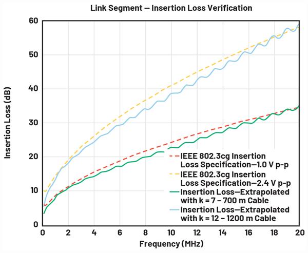
After the insertion and return losses are verified, the diagram suggests a method to estimate the maximum permissible length that meets the specifications. This is achieved by multiplying the measured insertion loss by a factor k to obtain a curve as close as possible to that one described in Equation 1 for the 1.0 V p-p or Equation 2 for the 2.4 V p-p transmission levels. By multiplying by factor k, the extrapolation estimates the insertion loss for a cable of the same type but extended to k times the length of the tested sample. The goal is to determine the maximum k where the extrapolated insertion loss curve remains below the required specification curve, adjusting k iteratively during the extrapolation process.
The following example can be used to illustrate this method and assumes the insertion loss and return loss have been measured.
Step 1: Return Loss Verification
Figure 8 shows the return loss verification of Cable X of a given type and a length of 100 m and the return loss specifications for both IEEE 802.3cg and APL. Note that every point in the measured return loss of the cable is greater than both APL and IEEE 802.3cg return loss specifications. This means that the measured cable complies with both return loss standards.
Step 2: Insertion Loss Verification
Figure 9. Insertion loss verification. Red dotted trace: IEEE 802.3cg maximum insertion loss for a 2.4 V p-p transmission level, yellow dashed trace: IEEE 802.3cg maximum insertion loss for a 1.0 V p-p transmission level. Solid blue line: measured insertion loss of 100 m Cable X.
The insertion loss can be verified by plotting the cable’s insertion loss against the specifications as shown in Figure 9. The insertion loss of Cable X was measured and is shown in solid blue. Notice that this curve is well below both the 1.0 V p-p and 2.4 V p-p 10BASE-T1L specifications plotted in the dotted and dashed red lines. This means that any 100 m link of this exact same type of Cable X can be used in 10BASE-T1L links for either 1.0 V p-p or 2.4 V p-p.
Step
3: Calculation
of maximum length compliant with IEEE 802.3cg
Standard
This section focuses on the IEEE 802.3cg standard and not on the APL classification. However, a similar analysis can be made in accordance with Table 1.
The measured insertion loss can be extrapolated by multiplying each data point by a factor k so that the resulting curve, when plotted against either the 1.0 V p-p or
Figure 8. Return loss verification. Blue shows the measured return loss of a cable of a given type. The yellow trace lines show the APL return loss specification and the red trace lines show IEEE 802.3cg return loss specification.
2.4 V p-p standard, falls below either of the two curves, depending on the transmission amplitude to be utilized.
Figure 10 shows the IEEE 802.3cg insertion loss specifications for 1.0 V p-p and the extrapolated curve obtained by choosing k = 7 (green line). The curve in green was obtained by multiplying each data point of the insertion loss of the 100 m cable sample by k = 7. Notice that the extrapolation obtained is just below the 1.0 V p-p specification, meaning, that 700 m (resulting from multiplying k = 7 times the cable’s length) is the approximate maximum length compliant with the 1.0 V p-p transmission level in non-APL applications. Any length below 700 m is also compliant with the 1.0 V p-p transmission level specification.
Similarly, Figure 10 shows the IEEE 802.3cg insertion loss specifications for 2.4 V p-p and the extrapolated curve obtained by choosing k = 12 (blue line). This curve was obtained in a similar way as explained above, by multiplying each data point of the insertion loss of the 100 m cable sample by k = 12. Notice that the extrapolated curve is also just below the 2.4 V p-p specification, meaning that 1200 m is the approximate maximum length compliant with the 2.4 V p-p transmission level (based on its insertion loss). Any length below 1200 m will also be compliant with the 2.4 V p-p specification.
The above analysis concludes that, based on the insertion loss and return loss criteria, the maximum permissible link segment for this specific cable type in non-APL applications is approximately 700 m for the 1.0 V p-p and 1200 m for the 2.4 V p-p transmission levels. However, for applications requiring full compliance with the standard, the maximum link segment must not exceed 1000 m.
This methodology can be applied to other cable types, potentially resulting in maximum compliant link segments of less than 1000 m. For instance, when similar assessments are conducted on Cat5/Cat6 cables, the typical maximum length compliant with the 10BASE-T1L standard is generally no more than 700 m, although this can vary depending on the specific cable brand and model, as some may offer additional margin.
Cable testing to estimate maximum reach
Cable testing procedures involve using a vector network analyzer to estimate the cable’s parameters and ADI’s EVALADIN1100EBZ evaluation kit to perform Ethernet traffic tests. The evaluation kit features a media converter functionality and provides access to diagnostics features (such as frame generator, frame checker, mean square error, and loopback modes) through
Figure 10. Insertion loss extrapolation of Cable X to obtain the maximum cable length compliant with the IEEE 802.3cg 1.0 V p-p and 2.4 V p-p specifications.
its evaluation software.
Testing procedure
Cable testing includes measuring the insertion and return loss of the cable under test using a vector network analyzer. These parameters are then used to evaluate cable compliance and estimate the maximum cable length compliant with the IEEE802.3cg 10BASE-T1L standard. The maximum compliant lengths correspond to the maximum lengths of the specific type of cable still compliant with the 2.4 V p-p or the 1.0 V p-p insertion loss curves as defined in the IEEE 802.3cg, shown in Figure 2.
Further testing includes connecting two EVAL-ADIN1100EBZ evaluation boards through the cable under test to establish a 10BASE-T1L link. Subsequent link performance tests involve transmitting Ethernet traffic at full bandwidth using the onchip frame generator. The mean squared error (MSE) of the 10BASE-T1L link is monitored on each EVAL-ADIN1100EBZ board, along with the error count and the number of received Ethernet frames. Tests are marked as passing only if:
• 10BASE-T1L is established successfully.
• The MSE is better than –20.5 dB.
• There are no errors in the received frames during the execution of the test.
This test is conducted repeatedly for various lengths of the same cable type of cable to determine the point of failure. However, in some cases, the maximum tested
length corresponds to the maximum length available in the lab and not necessarily to the maximum reach of the cable. Similarly, in situations where the increments of cable length exceed 100 m, the identified failure point may not accurately represent the absolute maximum cable length.
For instance, if only 500 m segments are available, a successful link might be established using 1000 m (two 500 m segments connected), but fail at 1500 m. The true maximum length may be 1200 m, but this specific length is not available for testing, so the last recorded data point remains at 1000 m.
With the variety of cables that have been tested in the lab, the estimated maximum length compliant with the 10BASE-T1L standard for both transmission levels, and the tested lengths at both 2.4 V p-p and 1.0 V p-p using the EVAL-ADIN1100EBZ evaluation board have been evaluated.
Conclusion
The IEEE 802.3cg-2019 standard’s flexible cable definition supports a broad range of cable types previously used in older communication protocols, maintaining extensive reach to connect edge devices seamlessly through Ethernet connectivity without requiring gateways.
Hector Arroyo, Systems Applications Engineer, Analog Devices.
Learn More
Industrial Ethernet Book
The only publication worldwide dedicated to Industrial Ethernet Networking and the IIoT. Visit iebmedia.com for latest updates.
New website offers deepest, richest archive of Industrial Ethernet and IIoT content on the web.
View and/or download latest issue of Industrial Ethernet Book and past issues.
Search our database for in-depth technical articles on industrial networking.
Learn what's trending from 5G and TSN, to Single Pair Ethernet and more.
Keep up-to-date with new product introductions and industry news.
Special Report 2025: State of Industrial Connectivity
Cybersecurity, IT/OT convergence, and the impact of AI are some of the megatrends that are shaping the state of industrial connectivity in 2025. Global organizations are establishing technical priorities for industrial networks today to identify opportunities, overcome challenges and improve collaboration for success.
INDUSTRIAL CONNECTIVITY HAS BECOME vitally important to the success of smart manufacturing worldwide. So for this special report, the Industrial Ethernet Book reached out industry experts to learn about the state of connectivity in modern manufacturing. Not surprisingly, we learned the focus is on hardware and software solutions, cybersecurity and technologies such as cloud integration, convergent TSN networking, wireless communications and the emergence of Single Pair Ethernet.
What seems certain is that connectivity— the ability of machines, devices, and systems in industrial environments to exchange data seamlessly and reliably across all levels of automation – is currently undergoing a major transformation driven by digitalization, the push toward smart manufacturing and the needs of the Industrial Internet of Things.
Three pillars shaping evolution
Key technologies shaping factory connectivity focus on hyperconnectivity, interoperability, and cybersecurity.
According to Ken YT Lee, Head of Moxa Serial Device Sever Segment, the state of industrial connectivity including hardware and/or software solutions is evolving to provide greater levels of performance in smart manufacturing operations.
“Industrial connectivity is evolving rapidly to support the increasing demands of smart manufacturing,” Lee told the Industrial Ethernet Book recently. “Three key pillars are shaping this evolution: hyperconnectivity, interoperability, and cybersecurity.”
Lee said that hyperconnectivity reflects the growing need to connect a wide range of
devices and subsystems. In many industries, control-level components now connect to more than one higher-level system to maximize data availability and improve real-time decisionmaking.
“Interoperability ensures different systems and protocols can communicate effectively. As factories integrate more heterogeneous devices, connectivity solutions must support multiple protocols and provide seamless protocol conversion to enable reliable data exchange,” Lee said.
And he added that “cybersecurity is becoming a core requirement. As physical connectivity and system integration increase, protecting systems and data is critical. New connectivity solutions must meet both internal security policies and external regulations. This means implementing security features directly
"Hyperconnectivity reflects the growing need to connect a wide range of devices and subsystems. In many industries, control-level components now connect to more than one higher-level system to maximize data availability and improve real-time decision-making." -- Ken YT Lee, Head of Moxa Serial Device Sever Segment.
into hardware and software to safeguard operations.”
These trends reflect a shift toward industrial networks that are more connected, more intelligent, and more secure, creating the foundation for long-term success in smart manufacturing.
Impact of cybersecurity
Lee said tht cybersecurity is currently one of the most important forces shaping the development of industrial connectivity. While many field devices are built for long service life and stable performance, they now face new challenges as they must comply with security standards such as IEC 62443.
This is particularly demanding for edge-layer components, which often use lightweight embedded systems. To meet the requirements, future products must be secure by design, including features like encrypted communication, user authentication, and secure firmware updates.
“At Moxa, we see this shift clearly. Connectivity solutions must now not only deliver reliable performance but also provide built-in protection against cyber threats. Technologies that support centralized user management, automated threat detection, and compliance with global standards are becoming essential,” Lee said.
“By integrating security at the design level,
Modernizing Serial Connectivity in Critical Infrastructure
Across sectors like gas, water, and energy, aging serial devices remain essential to operations. Connecting these assets securely to modern networks is now a key focus for engineers and operators.
Recommendations from Moxa’s field experience:
• Choose plug-and-play serialto-Ethernet solutions to reduce integration time and cost. Device servers with Real COM and TCP/UDP modes allow legacy devices like meters and gauges to connect with minimal disruption.
• Prioritize cybersecurity at the edge. Look for serial device servers with built-in protections such as Secure Boot, TLS/SSL encryption, RBAC, and compliance with IEC 62443-4-2 SL2.
• Simplify deployment and maintenance through centralized configuration, built-in diagnostics, and multi-port flexibility.
For engineers seeking to upgrade connectivity without replacing existing infrastructure, modern secure device servers, such as Moxa’s new NPort 6100/6200 G2 Series, offer a practical path forward.
industrial networks can support the needs of modern automation while also protecting critical infrastructure from emerging risks."
Key technical benefits
For cybersecurity benefits, the new edge connectivity solutions and components
need to provide protected data streams and management interfaces only to authorized users. They must also be able to notify the system if any abnormal incident occurs.
This enables users to enforce a defensein-depth strategy, starting from the edge layer and extending across the core industrial
Diagnostic Switch Simplifies Testing
The Skorpion diagnostic switch is unique because it never learns MAC addresses and therefore floods traffic to all ports. This feature is ideal for network troubleshooting because all network traffic can be observed from any port using sniffer tools such as Wireshark® .
Wireshark Captures
"The digitalization and networking of production, product and customer data is the decisive factor for increasing the added value of companies and thus also a basis for the economic development of global regions. The EU Commission recognized this and published the EU cybersecurity strategy back in December 2020. It defines the requirements for resilience and attack defense for manufacturers of components and systems as well as for all major manufacturing companies. -- Jörg Brasas, Strategic Product Marketing - Business Unit Automation Infrastructure, Phoenix Contact.
network. It supports cybersecurity policies such as a zero-trust approach and centralized management for IT/OT convergence, including enterprise user authentication and Security Information and Event Management (SIEM). Moreover, in regions with stricter cybersecurity governance—such as NIS2 in Europe, which includes penalties for non-compliance—having secure edge connectivity products helps users meet audit requirements. These include protecting critical production data through authentication and encryption and fulfilling security incident reporting obligations. This requires detailed incident logging that captures full contextual information from the edge device, such as who was involved, what happened, when, where, why, and how.
Engineering challenges
“A growing challenge in industrial environments is the knowledge gap between traditional OT systems and the skills of younger engineers. Many new professionals are experienced with cloud platforms, cybersecurity, and AI, but less familiar with legacy technologies such as serial interfaces and industrial protocols,” Lee said. He added that modern connectivity solutions are helping bridge this gap. They must be
intuitive, easy to configure, and efficient to troubleshoot, especially for users without deep OT experience.
Moxa’s next generation secure serial-toEthernet device server NPort 6000-G2 is one example. It includes a built-in web interface that allows users to monitor live Ethernet and serial traffic directly in the browser. This removes the need for additional tools, such as managed switches for port mirroring or serial monitoring software and allows troubleshooting from any device with a browser.
This user-friendly design simplifies complex tasks, reduces downtime, and makes industrial systems more accessible. Looking ahead, this kind of innovation will support the next generation of engineers and help manufacturers move forward with their digital transformation goals.
Advancing connectivity
Guided by cloud integration, convergent TSN networking, wireless communications and the emergence of Single Pair Ethernet.
According to Dipl.-Ing. Jörg Brasas, Strategic Product Marketing - Business Unit Automation
Infrastructure, Phoenix Contact GmbH & Co. KG, the state of connectivity is being guided by cloud integration, convergent TSN networking, wireless communications and the emergence of Single Pair Ethernet.
Here is how Brasas summarized these factors and how they are affecting connectivity in the smart factory:
Seamless communication from the sensor to the cloud: The big goal is "seamless communication from the sensor to the cloud", i.e. all data is available where it is needed in real time with minimal effort. The current state of industrial connectivity is that powerful network structures exist in OT today, but further challenges still need to be solved.
Convergent networks through TSN (Time-Sensitive Networking): TSN is a key technology for the convergence of networks. It enables the integration of different types of data traffic in a single network. Real-time critical applications (e.g. fast control, signal acquisition in energy networks or motion control) and data-intensive applications (e.g. video streams or IT systems) can be operated in parallel via one network.
Wireless real-time communication with 5G and Wi-Fi 6: 5G and Wi-Fi 6 are crucial for real-time wireless communication in smart
factories. 5G offers ultra-reliable, low-latency communication (URLLC), which is essential for industrial applications such as controllers and actuators. Wi-Fi 6 complements this with high data rates and improved network performance in dense environments.
Integration of sensors and actuators through SPE (Single Pair Ethernet): SPE enables the simple and cost-effective integration of sensors and actuators into industrial networks. It offers reliable data transmission and power supply via a single line-line pair, which simplifies installation and maintenance and increases flexibility.
Technology solutions
“Industrial connectivity is driven by several key trends and specific technology solutions that significantly impact the performance of automation and machine networking,” Brasas told the Industrial Ethernet Book.
Important trends in automation are:
1. Industrial Internet of Things (IIoT): IIoT provides real-time information for better operational control and more efficient production. It optimizes maintenance processes, reduces downtimes and uses resources more efficiently. IIoT is scalable and adapts to your requirements. The aim of IIoT is to improve operational efficiency, reduce production costs, speed up processes and realize new business models. By
Innovation in industrial production is software driven, and innovative software solutions need efficient access to machine- and process data.
networking machines, production facilities and manufacturing processes, data analyses are carried out to optimize productivity, efficiency and maintenance in production.
2. Edge Computing: Edge computing brings intelligence close to the machine and therefore close to the data source. These
Designing safety loops?
intelligent systems can be used to implement the familiar concepts of Industry 4.0 or the Internet of Things (IoT). There are numerous areas of application - e.g. data collection and aggregation, data (pre-)processing and analysis through to the use of artificial intelligence such as predictive maintenance as
Explore Our Application Notes For Various SLA Safety Loop Designs.
With up to seventeen I/O channels, built-in voting and enhanced math/logic capabilities typically found in costly and complex safety PLCs, the SLA can handle everything from simple alarming to more complex logic schemes including 1oo2, 2oo3 or even 5oo8 voting architectures.
Call 1-800-999-2900 or visit www.miinet.com/sla-ieb for details.
“The Industrial Ethernet continues to replace traditional field buses. This trend is not new, but it is reinforced by recent developments such as the commercial availability of products supporting Ethernet-APL. Industrial communication is becoming faster, larger volumes of data can be transmitted, and users migrate their automation networks to Ethernet-based control,"-- Christopher Anhalt, Vice President - Product Marketing for Softing Industrial.
well as machine-to-machine communication or communication with higher-level systems, e.g. a cloud connection.
3. Cloud Computing: When cloud computing is mentioned, it is assumed that there is a connection to the cloud via the internet. In many applications, however, data must be collected, checked and fed back into the process in very short cycles. In such a scenario, a public cloud solution would not be suitable simply because of the latency times on the internet. Edge computing is therefore increasingly being used for such smart applications.
These technologies and trends are leading to:
Real-time data collection and analysis: Continuous monitoring and analysis of data from various sensors and devices helps to optimize production processes, reduce waste and increase overall efficiency.
Predictive maintenance: By analyzing data patterns, these solutions can predict equipment failures before they occur, enabling timely maintenance and reducing downtime.
Cloud integration: Cloud platforms provide scalable storage and computing power, allowing manufacturers to handle large amounts of data and complex analytics.
Edge computing: Processing data closer to its source reduces latency and bandwidth consumption, making it easier
to scale operations and adapt to changing requirements.
Real-time decisions: Enhanced data collection and analysis capabilities enable faster and more informed decisions, improving responsiveness to market changes and operational challenges.
Increased collaboration: Connectivity facilitates communication and collaboration between different parts of the supply chain, improving coordination and reducing delays.
Overall, these advances pave the way for smarter and more efficient manufacturing processes and help companies to remain competitive in a rapidly changing market.
Engineering challenges
What are the engineering challenges and “pain points” that these new innovations are designed to address for customers? What is the future impact on manufacturing?
• No transparent communication without security: Key challenges and future implications for the manufacturing industry in the area of cyber security include:
• CRA (Cyber Risk Assessment): A thorough assessment of cyber risks helps to identify vulnerabilities and implement suitable protective measures.
• IEC 62443: This international standard provides a comprehensive framework for the safety of industrial automation systems.
• NIS 2.0 (Network and Information Systems Directive): This EU directive aims to improve cyber security in critical infrastructures.
“The digitalization and networking of production, product and customer data is the decisive factor for increasing the added value of companies and thus also a basis for the economic development of global regions. The EU Commission recognized this and published the EU cybersecurity strategy back in December 2020,” Brasas said. “It defines the requirements for resilience and attack defense for manufacturers of components and systems as well as for all major manufacturing companies. The international IEC 62443 series of standards describe basic requirements for preventing security risks for component manufacturers, system integrators and operators. It is the leading standard for the implementation of security-by-design in products and systems.”
He added that,”with a secure product development process certified according to IEC 62443-4-1 and IEC 62443-4-2 certified products, we ensure that systems planned today meet high security standards even after new cyber security laws such as the CRA come into force. This gives machine and plant manufacturers the planning security they need to meet the increasing security requirements of the future.”
Three pillars shaping evolution
Key technologies shaping factory connectivity focus on hyperconnectivity, interoperability, and cybersecurity.
Christopher Anhalt, Vice PresidentProduct Marketing for Softing Industrial Automation GmbH said that the state of industrial connectivity is being driven by the transformation already taking place in smart manufacturing.
“Industrial connectivity—the ability of machines, devices, and systems in industrial environments to exchange data seamlessly and reliably across all levels of automation –is currently undergoing a major transformation driven by digitalization and the push toward smart manufacturing,” Anhalt told IEB recently.
“The Industrial Ethernet continues to replace traditional field buses. This trend is not new, but it is reinforced by recent developments such as the commercial availability of products supporting Ethernet-APL. Industrial communication is becoming faster, larger volumes of data can be transmitted, and users migrate their automation networks to Ethernet-based control,” Anhalt said.
He added that, regarding OT/IT-integration, Ethernet-based communication with PLCs and field devices paves the way for connectivity solutions deployed on standard hardware, and the integration of machine connectivity with IT driven operation. Machine connectivity is no longer managed as an “autonomous production asset”, but as an extension of central IoT- or cloud platforms.
And solutions for industrial connectivity must not ignore cybersecurity, which is increasingly regulated (see, for example, the NIS 2 directive in the European Union).
Industrial connectivity trends
“Innovation in industrial production is software driven, and innovative software solutions need efficient access to machineand process data. Ethernet based industrial communication protocols provide the basis for such solutions,” Anhalt said.
IoT application developers and data scientists need easy access to semantic information. Users want to implement innovative “industrial data spaces” (“smart data lakes”, “Unified Name Spaces”) to simplify IoT application development, and to simplify work for data scientists.
Expanded OPC UA Functionality
The OPC UA standard was created to allow information to be easily and securely exchanged between diverse platforms from multiple vendors and to allow seamless integration of those platforms--and offers key technology for factory connectivity solutions.
One example is how Softing Industrial has added support for a standardized OPC UA Address Space across its SIS, edgeConnector, edgeAggregator, and edgeGate products. This feature significantly simplifies and unifies data integration from a wide variety of industrial sources.
The new functionality allows any data source — from PLCs and CNC controllers to Modbus sensors and MQTT data — to be integrated into a standardized OPC UA Address Space. The data is processed and presented in a consistent structure within the OPC UA server, regardless of its original format or communication protocol.
“Our goal is to drastically reduce the complexity of industrial data integration,” said Andreas Röck, Product Manager at Softing Industrial. “With the standardized OPC UA Address Space, we enable consistent, interoperable data access across all levels — from the shop floor to the cloud.”
Learn more -->
Standardized information models such as OPC UA companion specifications, deployed at the interface between OT and IT, and between multiple production sites and a central platform, help implement IoT solutions which offer such centralized access to automation network data.
“The need for increased productivity and efficiency of industrial production also drives a broader adoption of digital plant asset management (PAM) solutions. Connectivity solutions such as software-based HART multiplexers (e.g. offered by Softing’s smartLink product family) help customers connect more smart field devices – HART devices and others – to their PAM solution,” he said.
He added that the containerization of software-based connectivity solutions allows customers to deploy industrial connectivity on modern IT infrastructure such as Kubernetes cluster.
New connectivity solutions
Anhalt said that new connectivity solutions support the transmission of larger data volumes, at higher speed, and with lower latency.
SOURCE: SOFTING
“Improved security features and support for standardized protocols like OPC UA and MQTT help ensure compliance with evolving cybersecurity regulations. The support of modern IT infrastructure improves scalability and robustness of the connectivity solution,” Anhalt said.
The deployment of OPC UA companion specifications close to the data source, as supported for example by Softing’s edgeConnector product family, makes semantic information available for computation on edge level. It also reduces the amount of data which needs to be transmitted to a central platform.
Addressing engineering challenges
Anhalt said that new innovations simplify network- and system architectures, for control in automation networks, as well as for digital plant asset management and for IoT solutions. They enable the scalable deployment of IoT applications across multiple production sites. Migration to Ethernet-based control is becoming easier. And new innovations help users to deal with security threats.
“New innovations also take organizational challenges into account, such as support of efficient operating procedures, and the support of technologies which match the skill sets of typical users,” Anhalt said. “Together, these benefits lead to greater operational efficiency, higher uptime, and more agile, data-driven manufacturing processes—key enablers for successful digital transformation.”
Al Presher, Editor, Industrial
EU Cyber Resilience Act (CRA) compliance for CIP devices
As the EU’s Cyber Resilience Act approaches enforcement deadlines, industrial product vendors must prioritize cybersecurity to ensure compliance with this important regulations. by leveraging CIP Security mechanisms, vendors can meet regulatory requirements, protect critical infrastructure, and ensure the long-term security.
AS THE EUROPEAN UNION’S CYBER RESILIENCE Act (EU CRA) moves towards enforcement deadlines, vendors of industrial products face increasing pressure to ensure their products comply with cybersecurity requirements. This regulation emphasize the need for robust cybersecurity measures in industrial products, particularly focusing on communication protocols and secure development practices.
CIP (Common Industrial Protocol) Security plays a crucial role in securing Industrial Control Systems (ICS), offering confidentiality, integrity, authentication, and non-repudiation. The implementation of CIP Security involves key aspects such as device identity management, secure communication protocols, and vulnerability mitigation, which are essential for compliance with the EU CRA.
This article explores CIP Security within the context of the EU CRA regulation, highlighting how it can be used as a cybersecurity technology to meet the imposed requirements. It identifies challenges faced by vendors in achieving compliance and discusses technology available to CIP-connected devices that can be used to meet various EU CRA requirements. Additionally, it surveys the functional requirements of Annex I Part 1 of the EU CRA.
The article aims to serve as a key resource for industrial suppliers and machine builders navigating the evolving regulatory landscape,
ensuring operational security, risk management, and long-term security of connected devices in industrial environments.
EU Cyber Resilience Act (CRA)
The European Union’s Cyber Resilience Act (EU CRA) is a landmark regulation aimed at enhancing the cybersecurity of connected devices within the EU market. The bulk of the regulation is scheduled for enforcement by December 2027, although some aspects come into force before then. The EU CRA mandates that manufacturers of hardware, software, and digital services must identify and mitigate cybersecurity risks throughout the product lifecycle. This includes implementing secure development practices, maintaining continuous compliance, and ensuring that products remain resilient against evolving cyber threats. The act is designed to protect users and systems from potential cyberattacks, promoting a safer digital environment across various industries. Furthermore, the act identifies certain functional requirements for products to meet, laid out in Annex I.
CIP Devices &
EU Cyber Resilience Act
EtherNet/IP and Common Industrial Protocol (CIP) are widely used in the industrial space, according to a study by HMS, as of 2024
these protocols are used in 21% of industrial network nodes [5]. The EU CRA plays a pivotal role for devices using EtherNet/IP in industrial automation.
The EU CRA mandates the integration of comprehensive cybersecurity measures, including secure communication protocols, device authentication, and vulnerability management, to meet compliance standards. By aligning with these regulations, device manufacturers not only provide capabilities to shield their devices from potential cyber threats but also foster greater trust and reliability within industrial automation systems.
Cyber Resilience Act significance for CIP Devices
Coming into effect in December of 2027, vendors do not have much time to ensure they are complying with this act. Given the short timeframe it is important for vendors to analyze the act in detail to understand how it affects their products. There are many aspects of this act, but some of the highly impactful aspects are the functional requirements given in Annex I, Part 1, clauses (1) and (2). This section of the legislation lays out specific requirements to which products must comply. For many EtherNet/IP devices, CIP Security can and should be used to meet many of these requirements.
The EU’s Cyber Resilience Act (EU CRA) is a landmark regulation aimed at enhancing the cybersecurity of connected devices within the EU market.
Before getting into specifics regarding CIP Security, it is important to keep in mind the text in (1) and (2) of Annex I. The text in (1) states: Products with digital elements shall be designed, developed, and produced in such a way that they ensure an appropriate level of cybersecurity based on the risks.
This text is important but somewhat generic. It does not give any specific requirements regarding what a product must support or any types of protections. That said, for a product supporting EtherNet/IP, CIP Security provides the strongest cybersecurity protection for the EtherNet/IP communication. Therefore, it is likely that this clause itself implies support for CIP Security for many EtherNet/IP products.
In (2) of Annex I, there is some text that precedes the enumerated requirements, which states: Based on the cybersecurity risk assessment referred to in Article 13(2) and where applicable, products with digital elements shall:
Again, this text is generic, but the important point is that all of the requirements enumerated as part of (2) of Annex I are subject to a cybersecurity risk assessment. This means that each product must undergo a risk assessment to determine applicability of a given requirement. Therefore, it is not possible for this article to provide universal guidance that applies to all EtherNet/IP products, as the risk assessment and intended use will vary between EtherNet/ IP products. However, this paper can provide some generic guidance regarding risks and mitigations, as it applies to EtherNet/IP.
After this first clause of (2) describing a risk assessment, the rest of (2) describes 13 requirements, enumerated as (a) through (m). As mentioned, each of these requirements will need to be evaluated for how they pertain to a given product based on cybersecurity risk. However, four of these requirements likely have a strong tie-in to CIP Security and the functionality that the various profiles provide.
CIP Security in CIP Devices for EU CRA Compliance
The different facets of CIP Security are explored with regard to their mapping to EU CRA requirements.
Secure by default
The first requirement with strong applicability to CIP Security is in Annex I, Part 1, 2(b), and the subject of it is making sure a product is shipped in a “secure by default” configuration. The full text of Annex I, Part 1, 2 (b) is as follows: be made available on the market with a secure by default configuration, unless otherwise agreed between manufacturer and business user in relation to a tailor-made product with digital elements, including the possibility to reset the product to its original state;
The first thing to note is that the text in Annex I, Part 1, 2(b) regarding secure by default
does not provide a lot of details regarding what is required to meet this. To that end, the following discussion presents a possible path for meeting secure by default for a CIP Security capable EtherNet/IP device. That said, this discussion exists at a snapshot in time and was based on current understanding of this requirement. As more is revealed the arguments here may need to be adjusted. Nevertheless, the hope is this provides some interesting thoughts on a possible path to compliance of the secure by default requirement.
The Pull Model (see Figure #1) operates automatically and by default on compliant devices, allowing them to independently locate a certificate authority and request a certificate for provisioning. While additional settings are needed to fully configure CIP Security, the certificate request can act as a trigger to deploy the complete security configuration to the device. There are already commercial solutions available that facilitate this process (for example, FactoryTalk™ Policy Manager), enabling full security configuration for an EtherNet/IP Pull Model device by default. It is important to note that devices typically can't be pre- configured with security settings tailored to a specific user, as they are generally produced for broader use and might be deployed across various environments and by various end users. Therefore, some user intervention is necessary for security setup. The CIP Security Pull Model simplifies this by allowing the device to automatically, and by default, initiate and complete the necessary steps for security configuration.
The CIP Security Pull Model is not mandatory
for all CIP Security devices, yet implementing this profile will of course be important for the secure by default requirement.
Devices in a networked system need to trust other devices and/or software to perform their essential functions; an EtherNet/IP device would of course need some provisioning of trust to properly function. As such, it is not feasible for a device to simply power up with all the security configuration necessary for runtime communication, rather there needs to be one or more steps towards provisioning, and these steps need to be performed by default, which is exactly what the Pull Model does. However, there may still be a question about a device that does not find an EST server via the Pull Model and therefore is not configured for security. In this case the user has elected to install the device in a network without an EST server, and by doing so is making a decision to override the default behavior of the device. This is allowed via the EU CRA, as the user ultimately can make their own decision about what level of security is appropriate.
Devices must ship in a secure by default state and close all non-essential ports and services by default, which very impacts the EtherNet/IP ports without TLS/DTLS cannot be turned on by default. One port that does not use TLS/DTLS is 44818/UDP. In the case of 44818/UDP, this port is only used for very limited functionality, mainly around device discovery, which in many plants is an essential function. Therefore, the risk of 44818/UDP being open is likely low, and it is reasonable to ship devices with this port open.
The other EtherNet/IP ports that do not
Figure 1. Example workflow for Secure by Default with EtherNet/IP Pull Model Profile
support TLS/DTLS are 44818/TCP, 2222/TCP and 2222/UDP. These ports do not support TLS/DTSL but support the general EtherNet/IP functionality. These ports will very likely need to be closed by default and require an explicit user action to enable them. That action could be via a software configuration tool that opens them using the TCP/IP Interface Object, or a hardware-based configuration (e.g. a physical switch on the product).
The CIP Security Pull Model can also help with this, as it executes by default and can be used to automatically deliver security configuration including certificates and port state. The default execution of the Pull Model provides a mechanism for only secure functionality to be enabled. That is, once Pull Model executes and identity and trust are provisioned the device is in the appropriately secured state as determined by the user. Before this occurs, the device is essentially in an open state, so if the user choses they may enable the EtherNet/IP ports that don’t have TLS/DTLS support, either via the Pull Model or via a different mechanism. The main point is that for the non-TLS/DTLS ports to be opened the user must take some explicit action; for ease of use this action can be tied to the CIP Security Pull Model and its operation.
A device may support multiple protocols beyond EtherNet/IP, and in such cases, similar security measures may be needed for those protocols, particularly if they pose significant risks as determined by the cybersecurity risk assessment (e.g. protocols that are used to control an industrial process might carry particular risk). One approach could be to disable these additional protocols by default, allowing them to be activated only by an authorized user. For protocols based on TCP and UDP, this can be managed through the CIP TCP/IP Interface Object. Once CIP Security is configured, access to this object is authenticated, enabling secure activation of other protocols. This method provides a simple way for an EtherNet/IP device to comply with the EU CRA's secure by default requirements, even when it supports other potentially highrisk protocols.
Unauthorized Access
The next requirement relevant for CIP Security is in Annex I, Part 1, 2(d) and is the subject of preventing unauthorized access to the product. The full text of Annex I, Part 1, 2 (d) is as follows: ensure protection from unauthorised access by appropriate control mechanisms, including but not limited to authentication, identity or access management systems, and report on possible unauthorized access; CIP Security offers several mechanisms to safeguard against unauthorized access. The EtherNet/IP Confidentiality Profile supports both certificates and pre-shared keys (PSKs), which can be authenticated through mutual
TLS. Both options provide robust cryptographic protection to prevent unauthorized access. Users have the flexibility to choose which method to implement and where to manage trust. For many EtherNet/IP devices, this approach is likely sufficient.
The CIP Security Resource Constrained Profile is designed for low-end devices, enabling the use of one or more pre-shared keys (PSKs) for establishing trust. These PSKs are verified through mutual authentication during the DTLS handshake. Despite the limited capabilities of these devices, PSKs offer strong protection against unauthorized access. Ultimately, the adequacy of this protection depends on the cybersecurity risk assessment, but for many constrained devices, it is likely to be sufficient.
In some cases, the cybersecurity risk assessment may indicate that additional protections are necessary to prevent unauthorized access beyond just certificates and PSKs. The CIP Security User Authentication Profile offers an extra layer of defense by enabling Role-Based Access Control (RBAC) on EtherNet/IP devices and allowing integration with external Identity Providers. This aligns well with requirements related to identity and access management systems, as the profile supports integration with any OpenID Connect identity management system. For highly complex devices frequently accessed by multiple users with varying responsibilities, the cybersecurity risk assessment may determine that RBAC, which is provided by CIP Security User Authentication Profile, is a robust
mitigation strategy.
Regarding the text in Annex I, Part 1, 2(d) about reporting unauthorized access, while the CIP specification includes error codes for such events, additional logging and reporting mechanisms are likely needed. Various options are available, including storing logs directly on devices. However, Syslog offers an appealing alternative, as it integrates seamlessly with many security monitoring services and solutions. Although Syslog is not currently a standardized component of CIP Security, it has been discussed at various ODVA forums and could potentially be incorporated in the future. In the meantime, vendors are encouraged to explore reporting options and consider Syslog as a viable solution and ODVA is also encouraged to consider standardizing Syslog as a new CIP Security Profile.
Confidentiality of transmitted data
The next requirement relevant for CIP Security is in Annex I, Part 1, 2(e) and is the subject of data confidentiality The full text of (e) is as follows: protect the confidentiality of stored, transmitted or otherwise processed data, personal or other, such as by encrypting relevant data at rest or in transit by stateof-the-art mechanisms, and by using other technical means;
This article will focus specifically on data in transit, as data stored within a product fall outside the scope of CIP Security and depend on the product's design. However, it is worth noting that data can be encrypted through software mechanisms. Furthermore, many embedded hardware platforms offer partial or full encryption for stored data, which could be utilized in this context. Additionally, the product might employ physical methods to protect data at rest, such as internal and inaccessible non-volatile memory.
CIP Security (Figure #2) enhances data confidentiality for EtherNet/IP by utilizing well-established encryption algorithms. The CIP Security EtherNet/IP Confidentiality Profile employs TLS and DTLS, requiring support for AES encryption, a globally trusted standard for safeguarding data. The Resource Constrained Profile also uses DTLS and supports both AES and ChaCha20, another highly regarded encryption algorithm. These algorithms are included in cipher suites within TLS and DTLS and offer strong protection for the confidentiality of EtherNet/IP data during transmission.
Users have the flexibility to choose which cipher suites to enable and may even opt for ciphers that do not provide confidentiality if desired, although the capability for data confidentiality is required for all CIP Security compliant devices. Ultimately, while CIP Security provides the tools for robust data protection, the choice of which measures to implement depends on the user’s assessment of cyber risk.
Figure 2. Trust for Data Confidentiality.
Integrity of Transmitted Data
The final requirement relevant for CIP Security is in Annex I, Part 1, 2(f) and is the subject of data integrity The full text of Annex I, Part 1, 2(f) is as follows: protect the integrity of stored, transmitted or otherwise processed data, personal or other, commands, programs and configuration against any manipulation or modification not authorised by the user, and report on corruptions;
This requirement closely resembles the previous one concerning data confidentiality, with the added inclusion of "commands, programs, and configuration." While both requirements still fall under the scope of a cybersecurity risk assessment, the expanded list in the data integrity requirement suggests that most data should be protected with integrity measures. The discussion here will once again focus on data in transit, specifically EtherNet/IP. While there are well-established methods for protecting data integrity at rest within a product, numerous options are available.
Data integrity is safeguarded through TLS and DTLS within CIP Security (Figure #3), with all the cipher suites required by the EtherNet/IP Confidentiality Profile offering strong integrity assurances via the SHA HMAC. Similarly, the cipher suites mandated by the CIP Security Resource Constrained Profile also guarantee data integrity, but through Poly1305 and AES-GCM authenticated encryption.
Even though the TLS/DTLS transport provides data confidentiality and data authenticity protections, it is important to note that some data has specific protections beyond the secure transport provided by TLS and DTLS. For instance, digital certificates used to establish the TLS and DTLS session, or Access Tokens in the User Authentication Profile, are individually protected by digital signatures, ensuring the integrity of this data. These mechanisms further enhance protection for critical information, forming the foundation for the security of the protocols themselves.
EU CRA compliance beyond CIP Security
As noted in the Introduction, Annex I of the EU CRA contains a set of requirements that apply to “products with digital elements.” Section II of this paper outlines how CIP Security can enable devices to meet some of the requirements related to network communication of the EU CRA. ODVA vendors should however be aware of the additional requirements that must be met in order to comply with the EU CRA.
The following subsections present a summary of the Annex I requirements, with brief commentary on the potential implications for ODVA devices. More detailed analysis is required in order to more fully guide vendors in achieving EU CRA compliance. It is beyond the scope of this paper to fully analyze all of the
EU CRA requirements in detail at this time. Note that there are requirements around technical documentation in Annex II and Annex VII, however these are not discussed.
Appropriate Level of Security
Requirement: (1) Products with digital elements shall be designed, developed and produced in such a way that they ensure an appropriate level of cybersecurity based on the risks.
Implications: Vendors should perform risk assessments and threat models of their products in order to determine the appropriate level of cybersecurity that is needed. Volume 8 (CIP Security) of the CIP Networks Specification is a good starting point, as it includes a threat model for CIP Security. Vendors also need to consider risks based on the industry segments and applications in which their products are used, and to consider threats beyond those addressed by CIP Security.
Known Vulnerabilities
Requirement: (2)(a) [products shall] be made available on the market without known exploitable vulnerabilities;
Implications: Vendors should implement a vulnerability awareness and tracking process, specifically applied to their own products, and also as applied to technology (network protocols, SDKs, operating systems, etc.) that their products incorporate. ODVA can in the future assist by providing a CIP vulnerability reporting and tracking process. Note that ODVA conformance test does not perform penetration testing on devices. To this end vendors must ensure they are taking responsibility for penetration testing and monitoring for vulnerabilities in any components they use, like a TLS library.
Secure by default
Requirement: (2)(b) [products shall] be made available on the market with a secure by default configuration, unless otherwise agreed between manufacturer and business user in relation to a tailor-made product with digital elements, including the possibility to reset the product to its original state;
Implications: Section II describes “secure by default” in the context of CIP Security. Vendors should also apply “secure by default” to any other protocols or interfaces that their devices support. For example, a device with an embedded web server should have HTTPS enabled by default with a process to bootstrap initial security for HTTPS.
Security updates
Requirement : (2)(c) [products shall] ensure that vulnerabilities can be addressed through security updates […];
Implications : Vendors need a mechanism by which they can update firmware and/or software in their devices or applications. It is assumed that ODVA vendors already provide this capability. To meet EU CRA requirements, firmware/software updates need to be done in a secure manner (i.e., following requirements for authorization, integrity, confidentiality, etc.).
Unauthorized access
Requirement: (2)(d) [products shall] ensure protection from unauthorised access by appropriate control mechanisms, including but not limited to authentication, identity or access management systems, and report on possible unauthorised access;
Implications : Refer to Section II for a discussion of CIP Security in the context of preventing unauthorized access. Vendors should also be aware to apply this to any protocols or interfaces in addition to CIP (e.g., HTTPS).
Confidentiality of stored, transmitted, or processed data
Requirement: (2)(e) [products shall] protect the confidentiality of stored, transmitted or otherwise processed data, personal or other, such as by encrypting relevant data at rest or in transit by state of the art mechanisms, and by using other technical means;
Implications : Refer to Section II for a discussion of CIP Security in the context of confidentiality of transmitted data. For stored or processed data, vendors need to evaluate the risks and attack vectors that are relevant to their products. For example, stored customer or application data may need to be encrypted, which can potentially be provided via the product’s hardware platform.
Integrity of stored, transmitted, or processed data
Requirement: (2)(f) [products shall] protect the integrity of stored, transmitted or otherwise
Figure 3. Trust for Data Integrity.
processed data, personal or other, commands, programs and configuration against any manipulation or modification not authorised by the user, and report on corruptions;
Implications: Similar to data confidentiality, refer to Section II for a discussion of CIP Security for transmitted data. For stored or processed data, vendors need to evaluate the risks and attack vectors relevant to their products.
Data minimization
Requirement: (2)(g) [products shall] process only data, personal or other, that are adequate, relevant and limited to what is necessary in relation to the intended purpose of the product […];
Implications: This requirement is more difficult to apply to CIP-based products and needs to be evaluated by vendors on a per-product basis. For example, the requirement could be interpreted to mean that a product should not storing customer application information or user authentication information beyond what is explicitly needed by the application.
Essential function availability
Requirement: (2)(h) [products shall] protect the availability of essential and basic functions, also after an incident, including through resilience and mitigation measures against denial-of-service attacks;
Implications: Protections provided by CIP Security contribute to protecting essential and basic function availability. There are additional considerations that vendors may need to address. At a minimum, in the event of a DoS attack such as a network storm, devices should not fault such that they require a restart to continue to function. Note that the EU CRA does not precisely define “availability of essential and basic functions”.
Vendors will first need to define the “essential and basic functions” for their devices. In addition futher investigation is needed in order to know more precisely what “protecting the availability” means in practice (e.g., as a certification body would interpret it). It may be that devices may require explicit measures to mitigate the effects of DoS attacks such as network storms and resource exhaustion attacks, e.g., via rate limiting.
Minimize negative impact
Requirement: (2)(I) [products shall] minimise the negative impact by the products themselves or connected devices on the availability of services provided by other devices or networks; Implications : Vendors should ensure that the product itself cannot be used as an attack vector in the system, e.g., via triggering of a storm of traffic or other unnecessary or unwanted communications. Products should limit their connections or communications to only that which is necessary for the application.
This could result in the need to allow users to disable certain functions such as network discovery.
Limit attack surface
Requirement : (2)(j) [products shall] be designed, developed and produced to limit attack surfaces, including external interfaces; Implications : Vendors should disable any non-essential TCP and UDP ports and/or other services and interfaces, by default, and require the user to explicitly enable any that are non-essential.
Reduce impact of an incident
Requirement : (2)(k) [products shall] be designed, developed and produced to reduce the impact of an incident using appropriate exploitation mitigation mechanisms and techniques;
Implications : Vendors should consider mitigation mechanisms that could be put in place to minimize impact in the event of the device being compromised. For example, unauthorized access by one user account should not allow an attacker to compromise other accounts or data. This requirement could be considered related to a number of other requirements. E.g., by providing confidentiality and integrity of data, impact of an incident can be reduced.
Recording and monitoring
Requirement: (2)(l) [products shall] provide security related information by recording and monitoring relevant internal activity, including the access to or modification of data, services or functions, with an opt-out mechanism for the user;
Implications: Products need to have some form of secure logging capability used to record actions especially as they relate to security capabilities and activities. A recommended solution is to use Syslog, as it is widely supported and used in the IT space.
Secure reset
Requirement: (2)(m) [products shall] provide the possibility for users to securely and easily remove on a permanent basis all data and settings and, where such data can be transferred to other products or systems, ensure that this is done in a secure manner.
Implications: The CIP Identity Object already includes the Reset service, which allows a device to be returned to its factory-default settings. It may also be necessary, depending on the product and application, to ensure complete erasure of any stored application data or settings in embedded memory.
Vulnerability handling requirements
Part II of Annex I contains requirements of manufacturers for managing vulnerabilities. It is beyond the scope of this paper to examine each
of the vulnerability-handling requirements. In summary, device vendors will need to establish a formal process to:
• Identify and document known vulnerabilities,
• Address and remediate any vulnerabilities,
• Provide for software and/or firmware updates that address reported vulnerabilities,
• Regularly test and review devices for security vulnerabilities,
• Disclose and communicate information about reported vulnerabilities to end users.
Conclusion
As the EU’s Cyber Resilience Act (EU CRA) approaches enforcement deadlines, industrial product vendors must prioritize cybersecurity to ensure compliance with this important regulations. CIP Security plays a pivotal role in protecting CIP-connected devices and Industrial Control Systems (ICS), providing essential features like confidentiality, integrity, authentication, and non-repudiation. By adhering to the principles of secure by default, ensuring data confidentiality and integrity during transmission, and minimizing unnecessary data exposure, manufacturers can safeguard against unauthorized access and mitigate cyber risks.
Furthermore, it is important to note that although CIP Security can be used to meet some of the EU CRA requirements, there are requirements which are not within the scope of a communication protocol like EtherNet/IP with CIP Security. Vendors will need to perform a cybersecurity risk assessment to determine all of the necessary features and technology for ensuring compliance to all requirements in the EU CRA. To assist with this, part III provides an introductory discussion of the Annex I Part 1 requirements and how they might apply to an EtherNet/IP device. However, each device will have its own specific nuances which need to be accounted for by the vendor.
In summary, by leveraging CIP Security mechanisms for compliance with the EU CRA, industrial product vendors can meet regulatory requirements, protect critical infrastructure, and ensure the long-term security of their connected devices in increasingly complex industrial environments. Although this is not the only work that is needed for a given product, it does represent significant technological solutions to meeting the requirements of the EU CRA.
Jack Visoky,Principal Engineer & Security Architect; Brian Batke, Engineering Fellow, Rockwell Automation ; Jegajith P.T, Chief Technology Officer; and Nithin S.P, EU Business Head, Utthunga
Learn More
Do you actually know… EtherCAT? Part 2
The first part of this EtherCAT series looked at how the technology works, key features and how EtherCAT and the EtherCAT Technology Group have developed over the last 22 years. In this issue, the critical topics include diagnostics, safety, the solutions EtherCAT offers and the protocol extensions EtherCAT P and EtherCAT G/G10.
THIS SECOND PART OF A THREE-PART SERIES, " Do You Actually know ... EtherCAT?", focuses on EtherCAT technology and critical topics including diagnostics, safety and what solutions EtherCAT has to offer here. We also find out more about the protocol extensions for EtherCAT P and EtherCAT G/ G10 communications.
Diagnostics with EtherCAT
In addition to key features such as high performance and speed, the availability of tools for network diagnostics also plays a key role in communication technologies for industrial environments. However, EtherCAT already has numerous corresponding features inherent in the system and fulfills two basic requirements for diagnostic in a network, namely fast response and precise analysis, “with on-board resources” so to speak.
In an EtherCAT network, incoming telegrams are checked for errors in each node. Only error-free telegrams reach the application, while faulty telegrams increase the error counters and are flagged so that subsequent nodes do not also increase their error counters. Such telegrams are also recognized as faulty in the controller, the EtherCAT MainDevice, and discarded. The MainDevice can precisely localize
errors by evaluating the counters. EtherCAT also detects rare faults at an early stage, minimizes their effects and thus facilitates error handling.
Each datagram contains a working counter for monitoring data consistency. Addressed devices increment this counter so that the MainDevice can check whether all devices have processed the data.
For developers, less for users, it is important that EtherCAT uses standard Ethernet telegrams, which can be evaluated with free analysis tools. The tool Wireshark, for example, can display information for EtherCAT in plain text.
In addition to the aforementioned diagnostic functions, the EtherCAT Technology Group offers a manufacturerindependent diagnostic interface by means of a corresponding specification (ETG.1510 Profile for Master Diagnosis Interface), which can be added as a software extension to any standard control implementation.
Safety over EtherCAT — safety included
In communication systems, safety is of course of the utmost importance. Here, the transmission not only of control information but also of safety-relevant data on one and the same medium is generally used.
EtherCAT relies on the safe protocol Safety over EtherCAT (FSoE), which has numerous other advantages.
For example, it offers flexible expansion options for the safety-relevant system structure as well as ready-made, certified safety solutions. FSoE also has many diagnostic options for safety functions and allows the safety concept to be seamlessly integrated into the machine concept. Development tools can support the programming of both standard and safety applications.
FSoE was developed in accordance with IEC 61508, is internationally standardized in IEC 61784-3 and can be used for applications up to a Safety Integrity Level SIL 3. With FSoE, the transport medium is regarded as a black channel and is therefore not included in the safety assessment. Basic EtherCAT remains single-channel and transmits safe and standard information in parallel.
The FSoE frames contain the safe process data as well as additional information on data security and are sent as a container with the process data of the communication. The transmission path is arbitrary and not limited to EtherCAT: the safety container can be transmitted via any fieldbus, Ethernet or similar communication technologies –regardless of the physical medium, even wirelessly.
This independence also simplifies the safety-related networking of system components. The safety container is routed via the control systems and evaluated in the other part of the system. Comprehensive emergency stop functions and targeted shutdown of machine modules can therefore be carried out without any problems, even if they are linked to each other via other communication systems such as Ethernet. The implementation of the protocol requires only a few resources and can achieve high performance and therefore short reaction times.
Figure 1: Overview of diagnostic options with EtherCAT.
EtherCAT for all cases
Since its introduction in 2003, there has only been one single version of EtherCAT. New features have always been added in a fully backward-compatible manner without changing the basic technology. Requirements that did not fulfill the original features of EtherCAT are managed via the protocol extensions that have been added over the years. This has many advantages and is also very attractive for cost reasons, not least when maintaining older systems.
EtherCAT P is used, for example, if power is to be transmitted together with data, and EtherCAT G/G10 is used in the rare case that the 100 Mbit/s bandwidth of EtherCAT is not sufficient.
Data under power
The EtherCAT P protocol extension expands EtherCAT to include power supply via a conventional, four-wire Ethernet cable, but remains identical in terms of protocol, which is why no new EtherCAT SubDevice Controller chips are required. In addition to the advantages of EtherCAT, EtherCAT P enables devices to be powered via the communication cable, which reduces cabling, cuts costs and saves space.
EtherCAT P is particularly suitable for self-contained machine parts or sensors that are integrated into the network via a P-coded M8 connector. The mechanical coding prevents mismating. EtherCAT P can be seamlessly combined with standard EtherCAT in the same network.
Communication at gigabit level
EtherCAT G extends the EtherCAT protocol to include data communication at gigabit level (1Gbit/s and 10 Gbit/s), which is ideal for applications with particularly high data volumes such as image processing, high-end measurement technology or complex motion applications. The features and benefits of
Figure 3: Easy and flexible safety architectures thanks to Safety over EtherCAT.
Figure 4: The Black Channel principle enables the use of the standard communication interface.
Figure 2: Principle of the controller-independent diagnostic interface.
Figure 5: EtherCAT safety container embedded in the process data of cyclic communication.
EtherCAT are retained, including IEEE 802.3 compatibility and flexible topology.
EtherCAT Branch Controllers integrate 100 Mbit/s segments and their parallel processing in a gigabit/s network. No additional tools are required and functions such as diagnostics and network synchronization are retained.
EtherCAT G/G10 offers increased bandwidth and reduced throughput times thanks to parallel processing, without the need for all field devices to be gigabitcapable.
Existing 100 Mbit/s devices remain usable and benefit from the technology extension.
In the next issue you can read more about… the EtherCAT Technology Group and the ecosystem around EtherCAT.
Christiane Hammel, EtherCAT Technology Group.
Figure 6: EtherCAT P –data and power supply in only one single cable.
Figure 7: Exemplary setup of an EtherCAT G/G10 network using specially developed EtherCAT Branch Controllers (EBC).
5G implementation of a CIP motion network
Use of the Wireless medium in motion applications requires some ability for the applications to be timesensitive below 250 microseconds. Findings suggest C2D and D2D (Sidelink) 5G applications are easy to implement and offer a robust toolkit for wireless CIP Motion.
USE OF THE WIRELESS MEDIUM IN MORE deterministic applications, more generally known as motion applications, requires some ability to be time sensitive to below 250 microseconds. This article examines the tools available to enable time synchronization and how they relate to CIP Motion. Investigations into adding Time synchronization to the hardware infrastructure found the latency on 5G is relatively closed loop motion control, which would not require infrastructure time synchronization, only peer to peer.
Using Precision time protocol in C2C (Controller to Controller), D2D (Device to Device), D2C (Device to Controller) and C2D (Controller to Device) theoretical applications, D2C and C2D applications where deemed the most feasible. In the applications Closed Loop
Motion control was the dominant solution for time synchronization
Our findings suggest C2D and D2D (Sidelink) 5G applications are easy to use and offer a robust toolkit for wireless CIP Motion.
A broader medium for motion protocols
For decades, the wireless medium has been seen as the medium of the future in all things communication. From commercial, to retail, and now to industrial, wireless communication seemingly solves many problems at once, from cable maintenance, to bends to use of multiple protocols under the abstraction layers, its connectivity and dis connectivity are ubiquitous and unseen.
These revolutionary appeals are seen
throughout our commercial and personal spaces, with around 147-158 Million wireless routers sold annually Yet the industrial market space has not seen the ROI in wireless as the commercial space has, evidence for this, such as limited adoption (5% of all factories) security concerns and limited growth (9% per year) although tertiary, is significant, although most industrial spaces double as an IT space, with wireless routers connecting many IT centric products, we have yet to see the exponential growth in this space, with an average 25% growth rate in the industrial market and 9% Year over Year Growth.
With new types of wireless protocols, such as wireless HART, Bluetooth LE, and 5G now being analyzed for the industrial world, perhaps these new avenues may push the
New types of wireless protocols such as wireless HART, Bluetooth LE, and 5G are now being analyzed for use in the industrial world.
industrial application ecosystem for adoption.
…and
a more narrow one
Although much of the industrial communications ecosystem is varied, much has been done, particularly with the 5G ACIA group, to identify and agglomerate the types of industrial communication based on application. In their working paper “Key 5G Use Cases and Requirements” real time, or RT use cases are well defined and targeted for specific applications.
Non-RT: Cycle times and latency are not critical; several seconds are regarded as sufficient Soft RT: Cycle times and latency are moderately critical, i.e. approximately one second
Hard RT: Cycle times and latency are highly critical, to within milliseconds or even microseconds
As Wi-Fi and Bluetooth have evolved to allow themselves into the industrial ecosystem, many of the Non-RT, and some soft RT types of applications have grown in their wireless uses. There continue to be many Non-RT and Soft RT solutions that continue to use cables for various reasons but it is not within the prevue of this article.
Inevitably, both Wi-Fi and Bluetooth have struggled to be applied to the Hard RT applications on the factory floor. This is mainly due to cycle with these technologies. Hard RT applications require millisecond, and in some applications, like motion, sub millisecond cycle time, also called network latency.
Built for latency, finally.
As wireless technology has evolved, cellular companies and organizations have seen themselves as the next generation of wireless technology. Cellular technology has evolved dramatically compared to wireless and Bluetooth. If measured in specification length, the 5G specification is a compendium of all cellular technologies, and around 100 times larger in page length compared to Wi-Fi 7 and
Bluetooth LE.
Cellular technology was first used as a replacement for phone cabling, mostly at government facilities. As well ports, mines and other large, networked areas have been using cellular technology on their industrial networks for quite some time. However, with the advent of 5G as a 3GPP specification, groups such as the 5G ACIA, and various companies have lobbied to enable this complex technology to add functionality to tackle these highly deterministic protocols. During some of 5G first releases, case studies were produced to showcase the ability to use 5G, specifically its dedicated channels, to significantly lower the
operational threshold for applications.
Initial discussions and case studies during 2017 3GPP meeting showcased some IEEE 1588 and TSN variant possibly being used as a medium to carry highly deterministic data. This case studies matured over release 15 into the penultimate standard in release 17. Release 17 built the ecosystem for which deterministic systems, as applied in the marketed role out of “instant action” of ultra reliability and <1 ms radio latency.
Release 17 pointedly added IEEE 1588 PTP support, not just IEEE 802.1AS gPTP. This included support for Boundary Clocks, Peer to Peer & peer to peer transparent clocks, and
Figure 1: 5G market capabilities.
more.
Now, to support the 1588 specification, is one thing, the next question is how to use it. The more abstract the use, the more difficult it is to set up in an application, and the less likely it will be adopted to the market ecosystem. Other types of Deterministic communications protocols are also looking at looking for methodologies to use the 5G protocol to lower integration times, higher scalability, and promote new, more wireless centric markets, such as ports and Mining.
CIP Motion and 5G
As has been previously demonstrated, EtherNet/IP can be run on 5G, due to the TCP and UDP protocol running in abstraction, the same as most applications, such as web browsers. However, CIP Motion is a special case.
5G base stations all have accurate time synchronization, due to two control plane variables and PTP grandmaster clock support . By mandatory requirements, this synchronization time is 1.5 µs, well below the latency time needed for most CIP Motion systems. The Figure 2 shows specific RAN (Radio Access Network) 5G applications.
As well, a Time Event Identifier all the 5G devices are time synchronized to the 5G base stations. The synchronization is needed for the radio communications to work.
We have found use of this Time Sync Variable
used on TDD or more requires less effort from the application and engineering support. With a 1.5 µs synchronization time, we can apply this to CIP Motion applications quite easily. Additionally, the coordination time for CoMP, Coordinated Multi-point technology is now used in most infrastructure products. However, there are other methods. Master clock thru the controller could be seen as a typical method for CIP Motion synchronization. However, this will need two-time domains:
• 5G time synchronized to TEI
• Controller time which can be free running or synchronized to a time reference of choice.
Then this clock will be distributed through the 5G network and the 5G time will be used to calculate what in PTP speak is called the residence time. Although the complexity seems minimal, there are some elements of diagnostics and maintenance which would need to be
Ericsson has already implemented time synchronization. The feature was called CIP9, now enabled inside of their TSN platform Regardless, this function now provides an information element which gives the time (of day) for the start of the next timeslot.
Other methods include using “Ethernet PDU (Protocol Data Frames)” for time synchronization along with QoS (Quality of Service) Configurations with TSN (1588). The positive aspect of Ethernet PDU’s is the 5G
SOURCE:
system handled the Ethernet Frames, creating an easy abstraction layer. A good example is the Ethernet PDU is a virtual ethernet cable connecting the user device to the network. However, problem arise when using the TSN time aware scheduler. The time aware scheduler IEEE 802.1Qbv is used to avoid head- of-line blocking on the TSN part of the network. 5G has its own way of eliminating head of line blocking, this adds complexity to an already complex tool. With CIP Motion, this could be done using the simplest Quality of Service Session, however, need for an Ethernet PDU is someone undemonstrated, as the Ethernet PDU enables complex time synchronization, like those which require a time aware scheduler.
Additionally, products with dedicated signals for time synchronization, such as Ethernet PHY (start of Frame) and signals integration with the radio module, would make it possible to connect non-5G enabled products to the 5G network with relative ease. 5G ACIA has included these signals in their working paper “ Exposure of 5G Capabilities for Connected industries and Automation Applications”.
CIP Motion with 5G Sidelink
5G Sidelink is a feature set of release 16 of the 3GPP defined specification. Although much of the Sidelink case studies defined by3GPP are automotive based, the device to device communication aspect could be beneficial to protocol sets such as CIP motion. CIP Motion supports multicast peer-to-peer communications, which allow position and velocity synchronization in drives controlled by multiple distributed controllers.
5G ACIA has done extensive research on this subject, building Case Studies and recommendations to 3GPP on further use of Sidelink for Industrial Applications. CIP Motion, with its use of 1588, makes use of Sidelink much easier, as QoS and various other implementation strategies unnecessary. Further Laboratory tests are required to understand implementation processes to build out use.
Rob Lodesky, Commercial Director, Industrial Network Communication, HMS Industrial Networks.
Learn More
Figure 1. Example workflow for Secure by Default with EtherNet/IP Pull Model Profile
CryoPhit USA delivers advanced automated cryotherapy solution
Advanced technology is empowering cryotherapy by offering seamless monitoring, diagnostics, and predictive insights. The solution had to do more than control and schedule events; it had to provide real-time data, predictive diagnostics, remote access and also integrate well with CryoPhit's HawkEye® app.
THE CRYOTHERAPY INDUSTRY HAS SEEN RAPID growth, becoming a staple in health and wellness spas, fitness centers, and medical practices. Cryotherapy uses extremely cold temperatures to reduce pain, decrease inflammation, and accelerate recovery, making it a popular choice for healing and overall wellbeing.
Cryotherapy has attracted a wide range of users, from athletes seeking faster recovery to individuals managing injuries, chronic pain, or pursuing general wellness.
As demand for cryotherapy expands, the challenge of designing reliable, easy-tomaintain systems has become increasingly important.
Cryo challenges
Traditional cryotherapy chambers have long relied on liquid nitrogen for cooling—a method that, while effective, comes with significant drawbacks. Liquid nitrogen (LN2) systems are expensive to operate, challenging to manage, and pose safety risks because they require
ultra-cold substances and proper ventilation.
To avoid these problems, CryoPhit USA™ of Spring Valley, CA specializes in cryotherapy chambers that use electric cooling systems, offering a safer, more reliable, and easier-tomaintain alternative. But these systems come with their own complications.
“Our biggest challenge was solving the complexity of cryotherapy systems—these are specialized refrigeration systems that very few technicians know how to maintain or repair,” says CryoPhit USA co-founder John Grettenberger.
“We needed a solution that could do more than just control and schedule events: it had to provide real-time data, predictive diagnostics, and remote access,” continues Grettenberger. All this functionality also needed to play well with their app, HawkEye®.
Cryophit USA
CryoPhit USA combines a modern vision with over 35 years of industrial refrigeration expertise. Founded by brothers John and
William Grettenberger, the company designs, builds, and sells cryotherapy systems to health and wellness facilities, offering both direct sales and ongoing service packages.
“People are taking personal responsibility for their health and not relying on a traditional medical model,” says John Grettenberger. “We want to be part of that.”
Evaluating options
“Traditional systems like standard PLCs are overly complex and expensive,” Grettenberger explains. “You’re dealing with multiple layers, costly hardware, VPN setups, and extra software that make scalability a challenge. They charge so much for hardware and software, and I just don’t get it.”
With affordability, product support, and ease of use at the forefront of their decision-making process, CryoPhit USA needed a solution that avoided unnecessary complexity while delivering reliable performance.
In his 35+ years in industrial refrigeration, Grettenberger has tried products from various
A CryoPhit USA cryotherapy chamber features an electric cooling system.
manufacturers.
SOURCE:
“I was introduced to Opto 22 first with SSRs [Solid State Relays], then the SNAP PAC system, which is an industry standard for freeze dryers, but builds, and sells cryotherapy systems to health and wellness facilities, offering both direct sales and ongoing service packages.
I hadn’t seen groov RIO,” says Grettenberger. “It looked perfect.”
Opto 22’s groov RIO edge device
“People are taking personal responsibility for their health and not relying on a traditional medical model,” says John Grettenberger. “We want to be part of that.”
The groov RIO, Opto 22’s compact industrial edge device, features 10 software-configurable I/O channels, allowing flexible control and monitoring without the need for additional modules.
Reviewing the system’s I/O requirements, Grettenberger determined that it would take two groov RIOs to provide all the inputs and outputs required to control their chambers:
• 8 thermocouples to monitor various refrigeration and environmental temperatures
• 5 pressure transducers to monitor health of refrigeration equipment
• 2 relay outputs to activate freeze and defrost functions
• 1 analog output to vary the speed of a fan that circulates cold air to maintain the -80 °C cryotherapy environment.
And after a feasibility consultation with their software developer, the team decided to move forward with the dual groov RIO design. At a price of under $1,000 per device, CryoPhit USA was able to develop and launch their entire control system on these rugged, compact, industrial edge devices.
Technology focus
“Our system is far simpler [than traditional PLC systems] and uses free tools like Node-RED, which integrates beautifully without requiring additional paid software licenses,” Grettenberger adds.
CryoPhit USA has made extensive use of Node-RED—a flowchart-based tool for IIoT processes and data integration, included with groov RIO—for handling various parts of their operation:
• Equipment monitoring groov I/O input nodes track temperatures and pressures of the refrigeration system to ensure optimal performance.
• Machine control groov I/O write nodes activate outputs that control the chamber’s temperature and operation settings in real time.
• Communication to energy monitor — Node-RED interfaces with a three-phase power monitor that tracks all electrical phases, allowing operators to monitor
A look inside a CryoPhit USA chamber's refrigeration and control system.
The groov RIO is at the heart of every CryoPhit USA control system.
kilowatt usage, calculate power costs over time, and generate detailed reports.
• App integration—using an MQTT publish/ subscribe topology, the groov RIOs publish data to AWS® (Amazon Web Services®) for integration with custom iOS® and Android® apps, developed by CryoPhit USA’s software developer.
• Historical data logging—a Microsoft® SQL Server® on the AWS cloud computing platform stores operational and performance data long-term.
As CryoPhit USA develops new, potentially larger and more complex systems, the scalability features of groov allow for easy expansion.
“If we need more I/O, we can just add another RIO module, giving us 10 more points. It’s efficient, adaptable, and fits our model perfectly,” says Grettenberger.
Technology impact
While CryoPhit USA achieved several key advancements with its electric cryotherapy systems, the most significant result has been the ability to diagnose 80% of issues remotely. This capability has addressed one of the cryotherapy industry’s biggest challenges: maintaining specialized refrigeration systems with minimal downtime.
A system once reliant on reactive troubleshooting now uses real-time monitoring and predictive diagnostics to prevent failures before they occur. CryoPhit USA's cryotherapy chambers minimize the need for on-site service visits, saving operators time and money.
Custom linear regression models improve failure prevention, predicting potential issues up to two weeks in advance, minimizing downtime and ensuring continuous operation— essential for operators whose revenue depends on uptime.
In addition to diagnostics, CryoPhit USA has delivered other impactful results:
• Energy management—Built-in tools track power usage, calculate costs per session, and generate detailed reports, providing operators with clear data on energy expenses.
• Scalable design—The modular nature of groov RIO allows systems to grow with customer needs, enabling easy expansion without requiring costly overhauls.
• Enhanced operator experience—Features like remote-start capabilities give operators full control from anywhere, ensuring chambers are ready to use before they arrive.
• Enhanced user experience —Users can also customize lighting and music before they begin their session, creating a personalized and immersive experience. CryoPhit USA has turned complex cryotherapy operations into a user-friendly, streamlined, data-driven process that maximizes uptime and makes daily management simpler and more efficient.
What's next?
CryoPhit USA remains committed to delivering reliable, straightforward cryotherapy systems, with no major changes planned for its product line.
Meanwhile, the Grettenbergers are expanding into industries with similar demands. As principals of TriplePoint Services, Inc.™, they design, manufacture, and service ultra-low temperature refrigeration equipment. One promising opportunity lies in pharmaceutical cold storage, where compliance with CFR 21 Part 11 requirements for secure and traceable data is critical. Using the same hardware and software framework as their cryotherapy systems—groov RIO, Node-RED, and AWS— they are developing new solutions under TriplePoint Services, Inc.
Case study by Opto 22.
Learn More
CryoPhit USA's custom app displays live data and allows setpoint adjustments.
SOURCE: OPTO 22
Operator UI on a CryoPhit USA cryochamber.
SOURCE: OPTO 22
Two groov RIOs handle I/O for each cryotherapy chamber.
Industrial AI: the bottom-up revolution
The evolutionary approach to industrial AI implementation, beginning at the component level, presents a practical alternative to comprehensive cloud deployments. It enables the gradual development of digital competencies, reduces investment risk, and ensures quick returns.
HIGH INITIAL COSTS, IMPLEMENTATION complexity, and lengthy return on investment remain: these misconceptions remain the primary barriers to artificial intelligence adoption in manufacturing. While most technology providers promote cloudbased solutions, an alternative approach is emerging: the gradual implementation of AI, starting at the component level. This strategy enables manufacturers of all sizes to harness AI potential effectively without significant upfront investment.
Intelligence at the component level
A significant proportion of manufacturing facility failures can be predicted through data analysis from individual components. Advanced yet effort-free analytics at the servo drive level enable self-monitoring and diagnosis of potential issues in surrounding machine parts. Frequency inverters utilize AI algorithms to diagnose the root causes of failures, while industrial robots enhance their paths in real-time, significantly boosting efficiency and improving quality.
A crucial element of this approach is the ability to respond instantly to equipment anomalies or predict them in advance. Intelligent components analyse data in real-time, enabling rapid parameter adjustment or machine shutdown before serious failures occur.
“Based on feedback from vast amounts of manufacturing facilities of all sizes we know that components equipped with AI-driven intelligence greatly reduce unplanned downtime. Such analytics happens automatically and does not require any knowledge in data science”, explains Piotr Siwek, Digital Director EMEA at Mitsubishi Electric Factory Automation.
From intelligent components to smart factory
The scalability of this approach to AI implementation significantly reduces deployment costs compared to comprehensive cloud solutions. After implementing intelligence on the component level, whole production lines can benefit from data analysis by integrating PLC control systems with AI algorithms. As factories face increasing demands for data analytics, edge-level solutions can be deployed while
keeping all the factory data in-house.
A significant advantage of this approach is enhanced data security. Local processing minimises the risk of cyber-attacks and data breaches, which is particularly crucial for manufacturing facilities working with sensitive data or technologies.
"The key to success is starting with small, measurable projects. In one European factory, we began with AI implementation in welding applications. Edge-level data analytics performed with MaiLab achieved nearly 100% accuracy of failure predictions. The quality results encouraged the client to expand the project across the entire production line", adds Siwek.
When cloud makes sense
Industry experts predict the growing importance of hybrid AI solutions,combining componentlevel analytics with selective cloud utilisation. Cloud solutions excel in cases requiring historical data analysis across multiple facilities or supply chain optimisation.
The cloud offers unparalleled capabilities in advanced big data analytics and machine
learning on large datasets. It is particularly valuable for global organisations needing to compare and optimise processes across multiple locations simultaneously.
"The future belongs to hybrid solutions. Our bottom-up strategy allows clients to build solid digital foundations and consciously choose which processes require cloud support", summarises Siwek.
The future is scalable
The evolutionary approach to industrial AI implementation, beginning at the component level, presents a practical alternative to comprehensive cloud deployments. It enables the gradual development of digital competencies, reduces investment risk, and ensures quick returns. As both organisations and their analytical needs grow, the system can be expanded with additional layers, including selective cloud utilisation where it brings the most value.
Technology article by Mitsubishi Electric.
Learn More
AI on a component level.
AI agents for industrial automation
AI agents from Siemens are designed to automate automation using Siemens Industrial Copilots. The future vision is an ecosystem of Industrial AI agents available on the Xcelerator platform with both Siemens and thirdparty AI agents. The goal is productivity aimed to increase by up to 50% for industrial companies.
SIEMENS IS HAS ANNOUNCED AN EXPANSION of its industrial AI offerings with advanced AI agents designed to work seamlessly across its established Industrial Copilot ecosystem. This new technology represents a fundamental shift from AI assistants that respond to queries towards truly autonomous agents that proactively execute entire processes without human intervention.
Siemens' new AI agent architecture features a sophisticated orchestrator. Like a craftsman, it deploys a toolbox of specialized agents to solve complex tasks across the entire industrial value chain. These agents work intelligently and autonomously – understanding intent, improving performance through continuous learning, and accessing external tools and other agents as needed. Users retain complete control, selecting which tasks they wish to delegate to AI agents.
Automating automation: how the AI agent architecture works
Siemens' approach distinguishes between Industrial Copilots, the interfaces users interact with, and the AI agents that power them behind the scenes. Furthermore, the company is developing digital agents, and integrating physical agents, including mobile robots. This way, Siemens is creating a comprehensive multi-AI-agent system where agents are highly connected and work collaboratively.
What sets Siemens' approach apart is the orchestration of these agents utilizing a comprehensive ecosystem. These agents not only work with other Siemens agents but also integrate with third-party agents, enabling unprecedented levels of interoperability.
To further accelerate adoption and innovation, Siemens is planning to create an industrial AI agent marketplace hub on the Siemens Xcelerator Marketplace. This marketplace will enable customers to access not just Siemens' own AI agents but also those developed by third parties.
All-encompassing Industrial Copilot
The Siemens Industrial Copilot, enhanced by Industrial AI agents, addresses every phase along the industrial value chain, across process and discrete industries:
Design Copilot: Currently available for NX CAD, helps users break new ground in creativity by accelerating the product design process.
Design engineers can navigate complex data, balance trade-offs, and perform multi- domain tasks more efficiently. The AI-powered assistant enables users to ask questions in natural language, quickly access detailed technical insights, and streamline complex design tasks – all leading to significant efficiency gains in product development. Siemens is also currently developing a Hydrogen Configurator for designing hydrogen production plants.
Planning Copilot: Currently in pre-release with customer testimonials already available, this solution optimizes production planning, resource allocation, and scheduling through generative AI-powered insights, helping manufacturers maximize efficiency and minimize waste.
Engineering Copilot: Available for TIA Portal with Managed Service coming in 2025, it enables engineering without repetitive tasks. As the first generative AI-powered product for automation engineering, it empowers engineers to generate automation code through natural language inputs, speeding up SCL code generation while minimizing errors.
In process industries, the copilot for P&ID Digitalization has already been tested by several customers. It’s an AI-assisted P&ID detection cloud service to digitalize and consolidate legacy P&ID diagrams.
Operations Copilot: Currently available for Insights Hub, the Copilot provides holistic insights into the entire plant. In addition,
at the machine level, Siemens is planning to introduce an Operations Copilot for shop floor workers, which will be available by the end of 2025. This new product is designed to empower shop floor operators, service technicians, and maintenance engineers to work more efficiently by querying machine data and receiving error resolution guidance through natural language. The Operations Copilot can be easily implemented at the machine level to provide machine instructions and operator guidance. For the process industries, the generative AI-based assistant Simatic eaSie, enables technicians and maintenance personnel to access relevant plant and equipment data via chat or voice interaction. This makes operations and maintenance more reliable and safer both in the control room and in the field.
Services Copilot: The Maintenance Copilot Senseye provides maintenance teams with expert-level equipment diagnostics without the need for specialized technical knowledge. Recently expanded beyond predictive maintenance to cover the entire maintenance lifecycle, this solution supports everything from reactive repairs to predictive and preventive strategies, with pilot implementations demonstrating an average 25% reduction in reactive maintenance time.
Technology article by Siemens.
Learn More
Siemens is expanding its industrial AI offering with advanced AI agents.
Understanding IP67 ratings for industrial networking devices
A certified IP Rating legitimizes an industrial network device and allows manufacturers to claim the level of protection their product delivers confidently. Manufacturers do not conduct their IP certification. Devices are tested by independent companies, such as UL, to replicate actual world conditions.
DUST AND WATER ARE ENEMIES OF sensitive electronic components. Once these contaminants are inside a device's enclosure, critical components may corrode and deteriorate, leading to overheating and eventual malfunction. Prevention relies on the enclosure's sealing effectiveness. So, how can we determine whether an enclosure suits the industrial environment in which it is deployed?
Enter the International Electrotechnical Commission (IEC). In 1975, the IEC created the Ingress Protection (IP) rating system to gauge a device enclosure's ability to keep out liquids and solids. Compared to ambiguous marketing terms like “waterproof” or “sealed,” the IP rating gives prospective buyers of industrial networking devices precise information regarding how well the enclosure will guard against the intrusion of external elements.
Industrial and network security device manufacturers, including Antaira, use IP ratings extensively. A certified IP Rating legitimizes an industrial network device and allows manufacturers to claim the level of protection their product delivers confidently. Manufacturers do not conduct their IP certification. Devices are tested by independent companies, such as UL, by performing a series of trials that replicate actual world conditions.
Using the IP rating system
The IP rating system is a practical and universally consistent way to determine the level of protection an enclosure offers a network device against environmental factors like dust and water. While IP ratings don't measure network performance or security, they ensure that industrial networking devices, such as industrial switches and routers, are shielded from physical damage in harsh conditions. By preventing the ingress of dust, moisture, and other harmful elements, IP-rated enclosures help maintain the reliable operation of network devices, enabling them to manage data network traffic more effectively, even in challenging environments.
The IP code has two digits: the first (ranging from 0 to 6) represents the level of protection against solid objects, with 0 indicating no protection and 6 meaning
complete protection against the ingress of dust. The second digit (ranging from 0 to 9K) denotes the enclosure's protection against moisture, from 0 (no protection) to 9K, which covers high-pressure hot water from various angles. Historically, a third digit was sometimes included to indicate the enclosure's resistance to mechanical impacts, but this has mostly been replaced by the IK rating system, which specifically measures impact resistance. If there is insufficient data to assign a specific protection level for either solids or liquids, an 'X' is used in place of a digit.
NEMA Versus IP in network protocols
The National Electrical Manufacturers Association (NEMA) establishes guidelines for producing electrical and medical imaging equipment. NEMA utilizes a standard rating system to define the environments and conditions suitable for installing multiple devices in multiple locations on the same network in an electrical enclosure.
Although both NEMA and IP ratings describe
the level of environmental protection an enclosure will provide to networks, they use different variables, so there is no direct correlation. In addition to water and dust, NEMA considers protection against rain, ice, snow, and accidental contact with electrical parts while indicating whether the installation is in an indoor or outdoor location and whether the area is flammable or non-flammable. Protecting internal networks from environmental hazards using appropriate enclosures is crucial to safeguard sensitive data and ensure network devices' security features and reliability.
Being familiar with the NEMA and IP rating systems is essential. This knowledge will prepare you to house network devices inside a NEMA-rated enclosure on DIN rails when different networks are deployed in complex networks in harsh industrial or remote areas, such as an offshore drilling platform. With this competence, for example, you can ensure reliable network connectivity even in demanding conditions.
Antaira Industrial Ethernet switch.
NEMA ratings consist of 10 different categories, each with data on its specific use:
NEMA 1: Designed for general indoor use
NEMA 2: Drip-proof for indoor applications · NEMA 3: Protection against dust, rain, and ice (indoor and outdoor use)
NEMA 3R: Protected from rain and sleet (outdoor use)
NEMA 3S: Dust-tight, rain-tight, and sleet-tight (outdoor)
NEMA 4: Water, dust, and sleet resistant for both indoor and outdoor use
NEMA 4X: Water, dust, and sleet-resistant, and corrosionprotected
NEMA 5: Indoor protection against dust and water dripping
NEMA 6: Protects against hose-directed water, temporary submersion, and external ice formation
NEMA 6P: Offers the same protection as NEMA 6 but with added resistance to prolonged submersion at a limited depth
NEMA 12: Safeguards against dripping and dust for industrial applications indoors
NEMA 12K: Protection against dust and dripping water, featuring knockouts for easy installation
NEMA 13: Designed for indoor environments, providing a sealed enclosure that prevents the entry of dust and oil
IP Ratings in industrial switches
Industrial switches are commonly installed in harsh environments, where they are subjected to dust, moisture, water immersion, chemical exposure, and other foreign objects. Another threat can come from cleaning systems with high-pressure streams that can jar connectors or lead to internal condensation. With the correct IP classification, industrial switches ensure reliable and uninterrupted computer network connectivity in challenging industrial environments. But how do you determine an IP rating? Begin by evaluating the area where the switch will operate to identify potential environmental hazards. Standards and regulations should be consulted as well.
Let’s look at three different situations:
1. Food and beverage production (wet environment): Cleaning is frequently needed in factories that produce, package, or ship
foods and beverages. Network devices in these areas should be rated to endure any necessary washdown procedures, necessitating a liquid IP rating of 5 to 8. The robust IP rating for solids is less critical and may not be as high.
2. Wood and metal working, synthetics, battery manufacturing (dusty environments): Process dust, another name for industrial dust, is generated during various manufacturing or production processes. Dust is produced, for instance, during cutting, drilling, grinding, or sawing. Another source of dust is the materials, powders, or ingredients used in the manufacturing process. An IP rating for solids of 5 to 6 is necessary to prevent dust from entering and building up in an enclosure. A high IP rating for liquids is likely unnecessary if the environment is non-hygienic, meaning less frequent washdowns.
3. Pharmaceutical plant (wet and dusty environment): Manufacturing solid and powdered drugs, vitamins, or nutraceuticals can create large volumes of industrial dust,
depending on the ingredients and processes. Pharmaceutical factories, like food and beverage plants, are subject to strict washdown procedures. Because hazardous levels of dust and water will threaten your network equipment and devices, a total IP rating of 55 - 68 should be considered.
Benefits of IP67 rating
The IP67 rating is a standard for ingress protection that ensures a device can withstand exposure to dust and water. In industrial networking, IP67-rated connected devices are essential for ensuring reliable operation in harsh environments. The benefits of an IP67 rating include the following:
Protection against dust and water ingress: Dust and water can damage network devices and disrupt network operation. IP67-rated devices are designed to prevent such ingress, ensuring the longevity and reliability of the equipment.
Enhanced reliability and uptime: Devices with an IP67 rating are less likely to fail due to outdoor environmental factors, leading to improved network reliability and reduced downtime.
Reduced maintenance costs: Since IP67-rated devices are more resilient to environmental damage, they typically would require less frequent replacement and maintenance in extreme conditions, resulting in cost savings.
Improved safety: IP67-rated devices are designed to operate safely in hazardous and high moisture environments, reducing the risk of accidents and ensuring personnel safety. Industrial networking applications can require an IP67-rated network device, such as an outdoor wireless access point. These devices are crucial for maintaining robust and reliable network connectivity in challenging conditions. Specifying the correct IP rating can significantly affect the performance and availability of industrial network devices. It could be the difference between your network running smoothly or experiencing costly production downtime.
Henry Martel, Field Application Engineer , Antaira Technologies.
IP Rating Chart.
HART remote communications
Moore Industries introduces HART tunneling for the HES HART to Ethernet gateway system which enables remote communication with HART field devices.
Moore Industries announces a significant feature update for the HES HART to Ethernet Gateway System, introducing HART Tunneling which enables remote communication with HART field devices. This new feature allows seamless bi- directional HART data transmission between PC-based HART software applications and HES connected field devices over Ethernet.
HART Tunneling with the HES permits users to send read and write HART commands remotely with any HART-capable software application, such as PACTware or an asset management system, through the HES without requiring physical access to field instruments. Acting as a gateway, the HES facilitates seamless HART communication between Ethernet and twisted pair networks, simplifying the configuration, monitoring, and diagnostics of remote HART devices.
Unlike costly and complex HART multiplexer systems, the HES now offers a simple and cost- effective approach for connecting to just one or a few critical remote HART devices over your facility’s local or remote Ethernet infrastructure.
Key features of HES
HART Tunneling:
Seamless Integration – Direct communication from PC-based HART software applications to field devices over Ethernet networks.
Enhanced accessibility: Remote configuration and diagnostics monitoring of HART field devices from a control room or off-site location.
Drivetrain Analyzer Cloud
Security measures: A security jumper on the HES enables or disables HART tunneling to address cybersecurity concerns.
Up to 20 percent in energy savings with Drivetrain Analyzer Cloud thanks to AI-based drive optimization.
Industrial companies are under pressure to improve energy efficiency and reduce their carbon footprint. A major energy consumer in industry is the drive train, which consists of variable speed drives, motors, pumps, and other components. Drivetrain Analyzer Cloud, a powerful solution from the Siemens Xcelerator portfolio, helps companies significantly reduce the energy consumption of their drive systems through energy-based maintenance.
Continuous monitoring and AI-based optimization for greater energy efficiency
The Connection Module IOT collects extensive data from the drive train and transmits it to the Drivetrain Analyzer Cloud. There, relevant operating data such as load, electrical power consumption and energy consumption of the drives are continuously calculated and displayed. Drivetrain Analyzer Cloud also helps to save energy by using advanced AI-based analysis algorithms to accurately detect deviations from the optimal operating point, monitor energy consumption, CO2 emissions, and costs, and generate optimization suggestions. Thanks to its data-driven approach, it even precisely calculates the
return on investment (ROI) so that future investments can be allocated as accurately as possible. This allows users to take targeted actions to increase energy efficiency: for example, adjusting the engine control, maintenance intervals, and load distribution. Drivetrain Analyzer Cloud also detects when an engine is operating inefficiently and
automatically recommends a more efficient alternative. Using Drivetrain Analyzer Cloud can reduce the energy consumption of a drive system by 10 to 20 percent.
Moore Industries
Learn More
Siemens
Learn More
CAN/FD Repeater Standard
The Ixxat CAN/FD Repeater Standard: uniting performance, simplicity and sustainability. The repeater is tailored to meet the needs of system integrators and plant engineers around the world.
HMS Networks has introduced the new CAN/FD Repeater Standard under its product brand Ixxat. As a crucial component for network infrastructures, the device solves several complex market challenges such as topology optimization, signal quality improvement, seamless integration in existing CAN networks, equipment protection by galvanic isolation and many more. The Ixxat CAN/FD Repeater Standard delivers an all-in-one solution for industrial communication. Easy to access, easy to understand and easy to use.
The CAN/FD Repeater from Ixxat is tailored to meet the needs of system integrators and plant engineers around the world, offering unmatched performance, ease of use and sustainability in one compact product. Designed to address diverse use cases with cost-efficiency, it is a true priceperformance champion.
Easy does it: handling and integration advantages The termination resistors are easily adjustable from the outside via piano switches. This means that users don’t have to open the housing for adjustment and the current switching status can easily be seen from outside. This feature simplifies installation and maintenance, saving valuable time.
The repeater additionally features push-in connectors for CAN/FD connections, drastically reducing maintenance efforts. This innovation enables a secure, tool-free connection for a seamless setup and operation. With it, connecting the device to the CAN lines can be done within seconds. Another feature is the built-in cable tie hole, that offers a practical solution for tidy installations, further simplifying cabinet organization. “The CAN/FD Repeater Standard provides many useful integration and handling features, that are scarcely available on the market combined in one product”, said Frank Iwanitz, Product Manager at HMS Networks. “With two CAN/FD channels it fulfills the most commonly needed CAN functionalities and on top unites several useability benefits at a competitive pricing.”
The Ixxat CAN/FD Repeater Standard delivers an all-in-one solution for industrial communication. Easy to access, easy to understand and easy to use.
labeling and intuitive LED indicators make operation straightforward, even for first-time users.
SOURCE: HMS NETWORKS
The CAN/FD Repeater Standard comes with a slim and compact housing, optimized for DIN-rail mounting, fits perfectly into control cabinets with limited space. Clear
EMI protection and easy termination
The new Repeater provides a 5 kV galvanic isolation between CAN channels and
the power supply, ensuring robust protection and system reliability, even in challenging industrial environments. “By using repeaters in CAN networks, connected equipment can be protected very easily”, Product Manager Iwanitz said. “It’s not only about the optimization of your network topology or optimizing your signal quality but about increasing and protecting the health of your whole CAN network. That’s a huge advantage users benefit from!”
Performant and sustainable at the same time
Aligned with HMS Networks' commitment to sustainability, the Ixxat CAN/FD Repeater Standard comes in eco-friendly packaging and does away with printed manuals, offering digital resources instead. It also debuts HMS Networks' new modern design, marking a fresh era for Ixxat products. “With our new cardboard packaging, we’re heavily reducing packaging costs”, Iwanitz said. “Additionally omitting the printed manuals is not only a consequence of the market feedback we received, but also a logical consequence of the HMS sustainability policy.”
The CAN/FD Repeater Standard is available on stock as of now at a list price of 222 Euro.
Key Technical Features
• Two CAN/CAN FD interfaces supporting arbitration rates up to 1 Mbit/s and data rates up to 8 Mbit/s
• CAN/FD Transceiver TCAN1044
• CAN connection: Removable Push-In Connectors
• Externally Switchable CAN bus termination resistors
• Galvanic Isolation up to 5 kV
• Operating Temperature -25 °C to +70 °C
• Protection Class IP20
• Dimensions 108 x 149 x 27 mm
• Power-efficient design operating at less than 100 mA at 24 V DC
• Compliance with CE and FCC certifications
Get more information on our website: www.hms-networks.com/can-fd-repeaters
HMS Networks
Distributed servos & power measurement
New distributed servo drive systems and EtherCAT power measurement terminals that offer safe power monitoring are among new products available from Beckhoff Automation.
AMP8000 distributed servo drive
The AMP8620 supply module and the AMP8805 distribution module are now also available with an extended voltage range for the AMP8000 distributed servo drive system from Beckhoff. There is also an additional option for controlling the holding brake for the AMP80xx distributed servo drive.
The AMP8620-2005-0x10 supply module is suitable for single-phase or three-phase voltage connection at 1 x 120...240 V AC and up to 8 A DC link output current or at 3 x 200...480 V AC and a maximum of 20 A DC link output current. The AMP8805-1010-0000 distribution module, which matches all AMP8620 supply modules, now offers an input voltage range of 155 to 848 V DC. The AMP80xx-xxx2 distributed servo drive is equipped with a holding brake and an M8 connection for manual control. This allows the holding brake to be controlled during mechanical installation or for service purposes if this cannot be performed by the main controller.
Learn More
Power measurement with safe power monitoring
The EL3453-0090 EtherCAT power measurement terminal has voltage inputs for direct monitoring of powerful generators up to 690 V AC, such as those commonly used in the wind energy industry. No upstream voltage transformer is required.
TwinSAFE SC technology now also makes it easy to implement safe power monitoring.
The TwinSAFE SC technology (TwinSAFE Single Channel) facilitates the use of standard signals for safety-related tasks in any networks or fieldbuses. The EtherCAT I/Os, such as the new power measurement terminal, are expanded to include the TwinSAFE SC function, but will retain their typical signal properties and standard functionalities.
The TwinSAFE SC technology facilitates communication by means of a TwinSAFE protocol. These connections can be distinguished from the usual safe communication by means of Safety over EtherCAT. The data of the TwinSAFE SC components are transferred to the TwinSAFE Logic, where they can be used in the context of safety- relevant applications, e.g., for safe power monitoring.
The four current inputs of the EL3453-0090 power measurement terminal are electrically isolated from each other and allow the terminal to be used in all common current
The AMP8000 distributed servo drive system is continuously being developed.
The TwinSAFE SC functionality of the EL3453-0090 is identified by a yellow stripe on the housing front panel.
transformer configurations such as 2- or 3-transformer configurations with star or delta connection including neutral conductor current measurement. The grid analysis is carried out up to the 63rd harmonic and also summarized in the Power Quality Factor for simplified diagnosis. Like all measured terminal data, the harmonic content can be read via the process data. In addition to the
“ExtendedRange” feature, which provides the full technical measuring range (130 % of the specified nominal measuring range), the EL3453-0090 now also offers TwinSAFE SC technology.
Beckhoff Automation
Learn More
SOURCE: BECKHOFF
Industrial data visualisation
GENESIS version 11 is engineered for rapid deployment featuring automated configuration tools, pre-built templates, and no-code engineering environments.
GENESIS version 11 is a major upgrade to Mitsubishi's flagship industrial data visualization and process control software eliminates tag count limitations and introduces a built-in industrial historian, transforming how manufacturers capture and analyse operational data. Designed for comprehensive industrial automation, monitoring and secure data management, GENESIS 11 allows companies to scale from small applications to enterprise-wide deployments without additional costs, while the embedded historian eliminates the need for separate data logging systems.
For nearly four decades, GENESIS has continuously evolved to meet changing industrial and regulatory demands, such as cybersecurity compliance through encrypted communications and integration with Microsoft active directories. From its early versions running on DOS and Windows, through 16-bit to 64-bit computing, GENESIS has been developed to keep pace with modern automation needs including realtime 3D visualisation and remote web-based monitoring. With its latest enhancements, GENESIS version 11 supports collecting, analysing and visualising data for a wide range of industries, including automotive, life sciences, smart buildings, and data centres.
Unrestricted licensing – a new standard in flexibility
GENESIS version 11 introduces unlimited licensing, removing restrictions on tags and client connections. This fundamental
GENESIS version 11 - Industrial data visualization and analysis platform with unlimited licensing and enhanced data protection.
shift eliminates traditional Digital Solutions platform pricing constraints, allowing manufacturers to expand their automation systems without additional licensing fees.
"This change redefines how automation projects are structured," said Christian Nomine, Strategic Product Manager Visualization & Analytics at Mitsubishi Electric Europe B.V. "By removing software limitations, customers can focus on innovation and scaling their operations freely,” Nomine added.
With lower upfront costs, Digital Solutions platforms become more accessible and budgetfriendly, enabling cost-effective implementation.
GENESIS version 11 dashboards.
SOURCE: MITSUBISHI ELECTRIC EUROPE
Built-In Industrial-Strength Historian for Smarter Decision-Making GENESIS version 11 introduces an integrated industrial historian, eliminating the need for third-party loggers and complex scripting. This built-in functionality collects, analyses, and visualises in real-time and historical data, allowing manufacturers to optimise performance, implement predictive maintenance, and make data-driven decisions with greater confidence.
"Having all critical data in a single solution, combined with advanced analysis tools, streamlines operations and enhances reliability," explains Nomine.
Enhanced real-time visualisation and control
The GraphWorX visualisation suite in GENESIS version 11 enhances real-time monitoring and control with 3D system monitoring, providing greater situational awareness and enabling engineers to identify and resolve performance issues more efficiently. The treemap control simplifies the detection of system anomalies, allowing for faster troubleshooting. Additionally, web-based access ensures secure remote monitoring, giving teams greater flexibility in managing operations. These improvements collectively enhance operational visibility and efficiency, helping manufacturers shift from reactive responses to proactive decision-making.
Mitsubishi
Learn More
SOURCE: MITSUBISHI ELECTRIC EUROPE
M23 motor connector for servo motors
New M23 motor connector for servo motors from LAPP designed for voltages up to 1,000 volts.
The EPIC® M23P A3 Quickflex circular connector from Lapp is designed for voltages up to 1,000 volts and can be used directly on the servo motor.
Servomotors are used wherever highprecision drives are required. They enable the exact control of angular positions, speed and acceleration and are therefore used in particular in industrial automation, for example in the control of axes in CNC machines, robots and conveyor belts, but also in production or the automotive industry. Reliable and robust connection solutions are required here to supply motors with energy and withstand the demanding industrial environments.
LAPP already has connection and control cables as well as servo assemblies that are specifically suitable for use on servo motors. With the new, rotatable EPIC® M23 Power angle socket, the world market leader is now launching a connector for direct connection to the servo motor, including signal transmission, especially for harsh environments where electromagnetic compatibility (EMC) is required, mechanically robust and available globally.
The rotatable and angled M23 motor
connector has a Quickflex quick-locking system that makes it easy for anyone to connect to the mating part. Locking takes place after just one eighth of a turn and can be plugged in with connectors of the market standard. The EPIC® M23P A3 Quickflex features the new and innovative Clean Design from LAPP and achieves protection class IP 68 when plugged
Raspberry Pi AI Camera
in, making it particularly easy to clean. The rotatable outlet on the motor allows an adjustable, defined outlet angle and therefore offers maximum flexibility when connecting.
New Raspberry Pi camera supports on-board camera processing for popular neural network models.
Farnell has introduced the new Raspberry Pi AI Camera, the latest innovation from Raspberry Pi that expands Farnell’s range of artificial intelligence devices.
At a cost of approximately $70 USD, the Raspberry Pi AI Camera - a collaboration with Sony based on its IMX500 Intelligent Vision Sensor - features on-module processing that is compatible with the entire Raspberry Pi single-board computer (SBC) range.
The Raspberry Pi AI Camera simplifies complex AI tasks at the edge because all processing is done on the Raspberry Pi AI Camera module itself, leaving the processor in the host Raspberry Pi SBC free to perform other operations.
Simon Wade, Senior Global Product Manager, Single Board Computing at Farnell, said, ”This new AI camera module is a remarkable addition to the Raspberry Pi range. As AI-driven applications proliferate across many industries, it shouldn’t surprise anyone that Raspberry Pi and Sony are leading the way to bring optic processing power to the edge. No matter which Raspberry Pi SBC you use, it is compatible with the AI Camera
module.”
The camera itself features Sony’s 12MP IMX500 Intelligent Vision Sensor with an integrated low-power inference engine that is pre-loaded with the MobileNet machine vision model. Its 76-degree field of view includes a manually adjustable focus; and comes equipped with 200mm cables for easy
connection with any Raspberry Pi SBC. The Raspberry Pi AI Camera is now available and shipping from Farnell in EMEA, Newark in North America and element14 in APAC.
Farnell
Learn More
SOURCE: FARNELL
Lapp Learn More
Wi-Fi 6 outdoor access points
Airolinx 6 Series rugged, outdoor Wi-Fi 6 access points offer connectivity up to 20 miles.
Antaira introduced its new Airolinx 6 Series of environmentally-hardened wireless access points. Featuring Wi-Fi 6 technology supporting speeds of up to 2400 Mbps, the Airolinx 6 it is optimized for high-bandwidth applications, including video surveillance, last-mile wireless backhaul, and intelligent transportation systems, with a maximum connectivity range of 20 miles. In addition, the Airolinx 6 Series' Power over Ethernet (PoE+) IEEE802.3at input enables single cable integration with PoE switches for simplified, cost-effective deployments.
The 6 Series is available in three versions:
Airolinx-6-IOM-IP67-T: Single-band outdoor AP with internal dual-plane omnidirectional antennas, providing seamless 360-degree coverage up to 2 miles.
Airolinx-6-EOM-IP67-T: Single-band outdoor AP with external dual-plane omnidirectional antennas, offering customizable coverage up to 2 miles. Additionally, this model supports a variety of alternate antennas, including dish, sector, horn, and panel antennas, providing versatility for specialized deployments.
Airolinx-6-ILD-IP67-T: Single-band outdoor AP with a long-distance 21dBi panel antenna, extending connectivity up to 20 miles.
Antaira Airolinx 6 Series wireless access points are housed in an IP67-rated enclosure providing ingress protection from dust, moisture and potential water immersion. A wide operating temperature range of -40°F to +167°F, along with resistance to winds up
to 120 mph, make these units designed for outdoor and harsh industrial use cases.
Improved data configuration and export
Solution Center features extensive innovations for the M100 I/O system.
Bachmann Electronic has released the latest version 4.80 of its M-Base software packet. A particular focus is on the “Solution Center” which features extensive innovations for the M100 I/O system. Users can export and import configurations at the “Channel”, “Module”, “Station” and “Network” levels in the new M-Base 4.80. In addition, the configurator displays the nominal power requirements of I/O modules and backplanes both individually and as a power balance, which supports the planning and optimization of systems. The SolutionCenter has also been updated to the latest Eclipse version.
In the area of the PLC Developer, there is the option to export libraries compiled and without source code. This increases the security and the degree of reuse of software components, which is particularly important for industrial applications.
Various improvements have been made to EtherCAT performance and configuration. A new monitor for display of the diagnostic history of subdevices and an option to configure subdevice-to-subdevice communication and PDO uploads offer greater transparency and
flexibility. The OPC UA client now supports up to 64 simultaneous connections to servers, which significantly increases the scalability and efficiency of communication.
The software oscilloscope Scope 3 has also been significantly enhanced. The list of recording channels can now be exported and reimported as a CSV file, which makes
it easier to create and edit them externally.
The time axis in the Scope 3 diagram allows fractions of a millisecond to be read, making diagnostics of fast processes much easier.
Bachmann
Antaira
Visit Website
Arm computers offer connectivity
New 64-bit Arm Computers with 5G / LTE / Wi-Fi 6 connectivity deliver trusted IIoT solutions, and deliver exceptional performance in industrial IoT applications.
Moxa Europe has announced the launch of its next-generation 64-bit Arm-based computers UC-3400A and UC-4400A Series featuring industry-leading dual-wireless, 5G/LTE and Wi-Fi 6, connectivity. Built around an Arm® Cortex-A53 quad-core processor and featuring dual-wireless connectivity, these computers are strictly tested to ensure reliable RF performance and deliver exceptional performance in industrial IoT applications.
With the rapid expansion of wireless connectivity in industrial environments, businesses are increasingly integrating 5G, LTE, and Wi-Fi 6 technologies to enhance operational efficiency and real-time data exchange. However, the growing number of wireless devices presents challenges in managing connectivity, ensuring security, and optimizing performance across different technologies.
To address these challenges, Moxa unveils its new 64-bit Arm-based computers, designed with a quad-core processor, reliable dual-wireless connectivity, simplified system software for easy development, IEC 62443-4-2 SL2 compliance, and a 10-year OS maintenance plan, including security patches and fixes. These computers deliver high performance with optimized energy efficiency, enabling customers to scale their IIoT applications reliably.
“Moxa is continuously investing in wireless communication technology including Wi-Fi, Cellular, and 5G, to ensure reliable connectivity to the cloud for edgecomputing devices, even in harsh industrial environments. Dual wireless connectivity ensures uninterrupted data transmission, maximizing productivity in IIoT applications,” said Ryan Teng, Head of Industrial Wireless and Arm-based Computer Segment.
High-speed Wireless and Network Troubleshooting Maximizes Productivity
The UC-4400A Series, Moxa's first 5G Arm-based computer with ultra-low latency, high connection-interface density, and enhanced reliability, empowers real-time data processing and connects highest number of devices to industrial applications.
Expansion modules for Wi-Fi 6E connectivity enhance the bandwidth and greatly reduce interference, enabling faster data transmission. In addition, Moxa’s partnership with Qualcomm for Qualcomm Extended Diagnostics Monitor (QXDM) provides advanced log analysis and troubleshooting support to further enhance the quality of wireless connections.
The UC-3400A and UC-4400A Series offer the advantage of dual wireless connectivity, integrating both cellular and Wi-Fi capabilities in a single computer.
Enhanced reliability and Pperformance With dual wireless Cconnectivity
The UC-3400A and UC-4400A Series offer the advantage of dual wireless connectivity, integrating both cellular and Wi-Fi capabilities in a single computer. This combination ensures connection redundancy for maintaining continuous operations even when one connection is down.
Moxa Connection Manager (MCM) utility provides seamless failover between cellular and Wi-Fi, enhancing system reliability. This makes the computers ideal for critical industrial applications that require uninterrupted data transmission. Additionally, load balancing can be used to optimize data traffic across both connections, further maximizing network performance and efficiency.
The UC-3400A and UC-4400A Series have been tested and certified globally for UL, FCC, CE, and RCM, as well as by North American carriers PTCRB, AT&T, and Verizon (UC-4400A expected to be certified in Q2 2025). In addition, the UC-3400A Series has been tested for ATEX and CID2 requirements in hazardous environments and is expected to be certified in Q2 2025. These certifications
ensure seamless and secure data transmission in diverse industrial environments and regions.
Designed for harsh conditions, the UC-3400A and UC-4400A computers can operate in the -40 to +70°C temperature range with wireless capabilities. The computers are ideal for applications in the distributed energy resources, industrial automation, and oil and gas sectors. With a 5-year product warranty and 10-year OS support, these products are built for long-term reliability.
IEC 624423-4-2 Security Level 2 Compliance
Moxa’s UC-3400A and UC-4400A Series computers with Moxa Industrial Linux (MIL3) and compliance with IEC 62443-4-2 Security Level 2 requirements, can save users several months of development time on security features. The secure operating system includes Secure Boot, a built-in security mechanism that ensures edge computers boot only from validated and authorized bootloader and operating system.
Moxa
SOURCE: MOXA
AMS Machine Works & Delta V software
Emerson’s Asset Management Software unifies equipment reliability data in a secure, easy-to-use integrated platform. The Delta V Automation Platform empowers manufacturers offering seamless data mobility solutions.
Emerson is helping reliability teams eliminate data silos and expand their capabilities with the release of AMS Machine Works version 1.8. This latest software update unites all modern AMS condition monitoring hardware data under a single platform to help organizations simplify management and increase cybersecurity of their reliability programs in a wide range of process industries, including oil and gas, chemical, life sciences, mining, metals, minerals, water, power and utilities, pulp and paper and more.
A key goal of Emerson’s Boundless AutomationSM vision is to enable seamless movement of contextualized data from the intelligent field, through the edge, and into the cloud to help teams drive more value from the data they already collect. By bringing all current generation AMS condition monitoring tools under a single platform, AMS Machine Works version 1.8 will contribute to that vision, helping reliability teams simplify the use of data for decision making and effective maintenance activities, breaking down silos to make plant personnel more effective and efficient in their roles.
Data from the AMS 2140 Machinery Health Analyzer will now feed directly into AMS Machine Works, and users will have the opportunity to maintain a single database combining both automated and manual data collection. In addition, a new user interface and improved dashboards will make the software easier to use, with the addition of drag-and-drop functionality and redesigned menus for more intuitive navigation.
Learn More
DeltaV™ Automation Platform
Updates to Emerson's DeltaV™ Automation Platform is empowering manufacturers with seamless data mobility across a new suite of life sciences software. Providing key automation solutions from the earliest stages of recipe development through commercial manufacturing, Emerson’s suite of life sciences software makes it easier for organizations to select and connect critical tools necessary to bring quality treatments to patients faster, safer and more sustainably.
The traditional process of creating a new treatment from research through clinical trials to commercial manufacturing is largely manual and intensely time consuming. Life sciences companies spend substantial resources in both time and money performing the steps necessary to move information across various applications to successfully develop
AMS Machine Works version 1.8 adds compatibility for AMS 2140 Machinery Health Analyzer with improved user experience and enhanced cybersecurity.
New, purpose-built, purpose-driven suite of products in DeltaV Automation Platform connect end-to-end from R&D through commercial manufacturing to get lifesaving therapies to patients faster.
and manufacture new products. With a wide variety of technology solutions from different providers in the various segments of the business, data can quickly become siloed in individual applications, making it difficult to move from stage to stage, and increasing the likelihood of error.
To overcome these challenges, Emerson’s life sciences software suite is purpose-built within the comprehensive DeltaV Automation Platform, streamlining the connection of critical components across the development and commercialization pipeline to create a more collaborative environment. For example,
users can create a general recipe and risk profile in DeltaV Process and Knowledge Management (PKM™), and then, using the DeltaV Tech Transfer Hub—a sophisticated mapping tool created through Emerson’s One-Click Technology Transfer™ initiative— quickly send the pertinent recipe information to the DeltaV Manufacturing Execution System (MES) or the DeltaV Distributed Control System (DCS).
Emerson
Learn More
SOURCE: EMERSON
Industrial Ethernet Book
The only publication worldwide dedicated to Industrial Ethernet Networking and the IIoT. Visit iebmedia.com for latest updates.
New website offers deepest, richest archive of Industrial Ethernet and IIoT content on the web.
View and/or download latest issue of Industrial Ethernet Book and past issues.
Search our database for in-depth technical articles on industrial networking.
Learn what's trending from 5G and TSN, to Single Pair Ethernet and more.
Keep up-to-date with new product introductions and industry news.