INDUSTRIAL INDEXING SYSTEMS, Inc. LUMINARY SERIES MOTORS & DRIVES
IB-30B001 USER’S GUIDE
SECTION 2 - PART NUMBER IDENTIFICATION 2.1
IDENTIFYING LUMINARY SERIES DRIVES
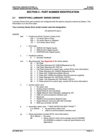
Luminary Series Drive part numbers are configured with the options using the scheme as follows. This information is on the Drive label: Your Luminary Series Drive model number uses this designation: LD-aaa/xzmmn-pyy-c WHERE: aaa
= Continuous Driver Current in amps (rms) 330 = 3.3 Amps (Servo Only) 500 = 5.0 Amps (Servo or Stepper) 101 = 10.0 Amps (Servo Only)
x
= Drive type: R = SERVO (5V Digital Inputs) S = SERVO (24V Digital Inputs) T = STEPPER (24V Digital Inputs)
z
= Feedback method: E = Encoder Feedback
mm
= Mounting plate: See Appendix A for further details 00 = No Plate 01 = Flat Plate (Standard AC-100619)(Replaced by 02) 02 = Flat Plate (Standard AC-100714) 0# = Flat Plate (where # is custom type, contact IIS for more information) 21 = “L” Plate (Standard AC-100603) (Replaced by 24) 22 = “L” Plate ((AC-100604 Drive/Motor Mount) 23 = “L” Plate ((AC-100604 Drive/Motor Mount)(customer supplied) 24 = “L” Plate (Standard AC-100720/AC-100721) 25 = “L” Plate, 10A (Standard AC-100739/AC-100721) 2# = “L” Plate (where # is custom type, contact IIS for more information)
n
= primary option card: 0 = No option card A = Analog Output interface B = Digital Network Card (Isolated) C = Digital Network Card (Obsolete, replaced by “B”) D = USB 2.0 communications interface card E = Reserved F = RS485 Communications Network Card H = Digital Network Card and LMC-400 Controller M = Multi axis controller LM-450
p
= secondary option card: ***(SEE NOTES ON NEXT PAGE)*** 0 or (Blank) = No secondary option card D = USB 2.0 communications interface card
yy
= Setup parameters (contact IIS for more information) 00 or (Blank) = No setup ## = Setup used for motor drive package (see SU-6000##) (SU-6000## is created to customer specifications and application)
OCTOBER 2018
PAGE 2 - 1
