Installation Guide
Your Single Source Solution


Your Single Source Solution
■ This manual includes all the necessary information about the use and the installation of the CLIM8ZONE unit.
■ The installer follow the installation instructions contained in the guide. Improper installation will void the warranty.
■ The manufacturer declines any responsibility for the damage caused by people, objects and errors due to the installation against the manual. Any use that isn’t in accordance with the origin of its manufacturing will be regarded as dangerous.
■ Do not use means to accelerate the defrosting process, other than those recommended by the manufacturer.
■ The appliance shall be stored in a room without continuously operating ignition sources (for example: open flames, an operating gas appliance or an operating electric heater.)
■ Do not pierce or burn.
■ Be aware that refrigerants may not contain an odor.
■ The CLIM8ZONE unit shall be installed, operated and stored in an open room larger than 3 m³.
■ Note the manufacturer may provide other suitable examples or may provide additional information about the refrigerant odor.
■ If you power Off the CLIM8ZONE unit, please empty the water in heat pump always during winter time or when the ambient temperature drops below 0°C, or else the titanium heat exchanger will be damaged because of being frozen, in such case, your warranty will be lost.
■ Please always cut the power supply if you want to open the cabinet to reach inside the CLIM8ZONE unit, because there is high voltage electricity inside.
■ Please keep the display controller in a dry area, or close the insulation cover to protect the display controller from being damaged by humidity.
■ Installation must be performed in accordance with the NEC/CEC and local code by authorized person only.
■ Make sure the switch is turned to the power off position before installing the CLIM8ZONE unit or maintenance the heat pump.
■ This appliance is not intended for use by persons (including children) with reduced physical, sensory or mental capabilities, or lack of experience and knowledge, unless they have been given supervision or instruction concerning use of the appliance by a person responsible for their safety.
■ Children should be supervised to ensure that they do not play with the appliance.
■ Single wall heat exchanger, not suitable for potable water connection.


Follow the minimum clearance requirements shown below during installation and operation of the CLIM8ZONE TM unit. These clearances insure proper air flow. All air vents must be unobstructed and free of debris.
DO NOT install the CLIM8ZONE TM unit indoors.
It is recommended that the CLIM8ZONE TM unit be installed no more than 6.5 feet (2 meters) from the Hot Tub.
CLIM8ZONE TM is compatible with the following spa controls.
The CLIM8ZONE TM unit is compatible with BP Control Systems that have one of the following agency prefixes: BP20, BP21, BP501, BP6, BP2, BP1. The agency prefix is noted on the control system identification label.
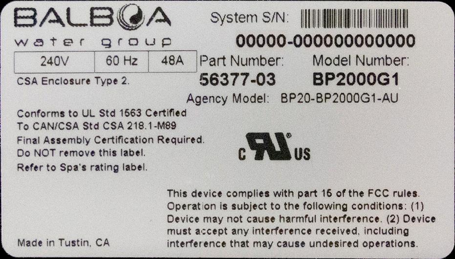


Control System BP Control System Identification label
AGENCY PREFIX

The agency prefix is noted on the identification label, which is on the top surface of the system pack. In this example the agency prefix is BP20.
Follow these steps to mount the CLIM8ZONETM unit to the platform.
1 - Establish the location of the CLIM8ZONETM unit on the concrete slab.
DO NOT install the CLIM8ZONE TM unit indoors.
It is recommended that the CLIM8ZONE TM unit be installed no more than 6.5 feet (2 meters) from the Hot Tub.
Follow the minimum clearance requirements (figure 3) to insure proper air flow.
2 - Each foot (figure 4, A) on the CLIM8ZONETM unit has a mounting hole. Clearly mark the center of each mounting hole on the concrete slab. Move the CLIM8ZONETM unit to make room for step 3.
3 - Using the marks from step 2 as a guide, drill one mounting hole for each foot into the concrete slab (figure 4, F).
4 - Clean the mounting holes (figure 4, G) and the cement slab, removing all dust and debris. If necessary used compressed air to clean the mounting holes.
5 - Move the CLIM8ZONETM unit back into its final position, making sure the mounting holes in the cement slab align with the corresponding mounting holes in the feet.
6 - Place a foot pad (figure 4, C) under each foot..
7 - Install the washer (figure 4, B), expansion wedge anchor (figure 4, E) and nut (figure 4, D) on each foot (A). Make sure the expansion wedge nuts are fully seated into the mounting holes (figure 4, H); use a rubber mallet if necessary.
8 - Tighten each expansion wedge anchor by turning the nut (figure 4, I).

Follow these steps to mount the CLIM8ZONETM unit to a platform.
1 - Establish the location of the CLIM8ZONETM unit on the platform (figure 5, A). Each foot on the CLIM8ZONETM unit has a mounting hole (figure 5, A). Clearly mark the center of each mounting hole on the platform (figure 5, A). In the next step you will drill a mounting hole for each foot (four total).
DO NOT install the CLIM8ZONE TM unit indoors.
It is recommended that the CLIM8ZONE TM unit be installed no more than 6.5 feet (2 meters) from the Hot Tub.
Follow the minimum clearance requirements (figure 3) to insure proper air flow.
2 - Using the marks from step 1 as a guide, drill one mounting hole for each foot into the platform (figure 5, B).
3 - Clean the mounting holes and the platform (figure 5, C), removing all dust and debris.
4 - Move the CLIM8ZONETM unit back to its final position, making sure the mounting holes in the platform align with the corresponding mounting holes in the feet.
5 - Place a rubber foot pad under each foot (figure 4, C). Rubber foot pads dampen vibrations.
6 - Install the washers, bolt and nut on each foot (figure 5, D).
7 - Tighten the nut (figure 5, E) on each foot.
Mounting hardware not included.
minimum load capacity: 300lbs (136 kg)

There are no user serviceable parts inside of the CLIM8ZONETM unit or the control system. All connections must be made by a qualified electrician in accordance with the country or local electrical codes in effect at the time of installation.
◆ Earthing is required for protection against short-circuits inside the unit. Always provide a good earth connection.
◆ Before connecting the unit, verify that the supply voltage matches the required voltage of the heat pump.
◆ It is recommended to connect the heat pump to a circuit with its own fuse or circuit breaker.
Follow these steps to make the electrical connections:
1 - Make sure the BP Control System (figure 6, B) is powered Off at the GFCI or circuit breaker before starting the installation process.
2 - Remove the lid from the BP Control System (figure 6, B) by loosening these two screws (figure 6, C) with a Phillips head screwdriver.
There is a wiring diagram in the inside surface of the lid. Refer to the wiring diagram during steps 3 and 4.
3 - Connect the power cord (figure 6, D) to the AV port on the circuit board of the BP Control System (figure 6, B). Refer to the wiring diagram for the proper connection. The connectors are keyed, so make sure they are properly aligned (figure 6, F) before making the connection. If the AV port is occupied, a splitter ((figure 6, H)(pn 22934, sold separately)) is needed.
4 - Connect the data bus (figure 6, E) to the circuit board of the BP Control System (figure 6, B). Refer to the wiring diagram for the proper connection. The connectors are keyed, so make sure they are properly aligned (figure 6, F) before making the connection.
5 - Reinstall the lid of the BP Control System (figure 6, B).
6 - Bonding: This unit is provided with a grounding lug (figure 6, G) and must be electrically bonded to the spa common bonding grid.
Connect the grounding lug with the spa common bonding grid with a #8 minimum solid copper wire.
7 - Power On the BP Control System at the GFCI or circuit breaker.
The connectors are keyed to help insure proper connections.
There are no user serviceable parts inside of the CLIM8ZONETM unit or the control system. All connections must be made by a qualified electrician in accordance with the country or local electrical codes in effect at the time of installation.
◆ Earthing is required for protection against short-circuits inside the unit. Always provide a good earth connection.
◆ Before connecting the unit, verify that the supply voltage matches the required voltage of the heat pump.
◆ It is recommended to connect the heat pump to a circuit with its own fuse or circuit breaker.
Follow these steps to make the electrical connections:
1 - Make sure the BP Control System (figure 7, B) is powered Off at the RCD or circuit breaker before starting the installation process.
2 - Remove the lid from the BP Control System (figure 7, B) by loosening these two screws (figure 7, C) with a Phillips head screwdriver.
There is a wiring diagram in the inside surface of the lid. Refer to the wiring diagram during steps 3 and 4.
3 - Connect the power cord (figure 7, D) to the AV port on the circuit board of the BP Control System (figure 7, B). Refer to the wiring diagram for the proper connection. The connectors are keyed, so make sure they are properly aligned (figure 7, F) before making the connection. If the AV port is occupied, a splitter ((figure 7, G)(pn 22934, sold separately)) is needed.
4 - Connect the data bus (figure 7, E) to the circuit board of the BP Control System (figure 7, B). Refer to the wiring diagram for the proper connection. The connectors are keyed, so make sure they are properly aligned (figure 7, F) before making the connection.
5 - Reinstall the lid of the BP Control System (figure 7, B).
6 - Power On the BP Control System at the RCD or circuit breaker.
The connectors are keyed to help insure proper connections.
There are no user serviceable parts inside of the CLIM8ZONETM unit or the control system. All connections must be made by a qualified electrician in accordance with the country or local electrical codes in effect at the time of installation.
◆ Earthing is required for protection against short-circuits inside the unit. Always provide a good earth connection.
◆ Before connecting the unit, verify that the supply voltage matches the required voltage of the heat pump.
◆ It is recommended to connect the heat pump to a circuit with its own fuse or circuit breaker.
Follow these steps to make the electrical connections:
1 - Make sure the BP Control System (figure 8, B) is powered Off at the RCD or circuit breaker before starting the installation process.
2 - Remove the lid from the BP Control System (figure 8, B) by loosening these two screws (figure 8, C) with a Phillips head screwdriver.
There is a wiring diagram in the inside surface of the lid. Refer to the wiring diagram during steps 3 and 4.
3 - Connect the power cable (figure 8, D) to the adaptor (figure 8, F). Connect the adaptor to the AV port on the circuit board of the BP Control System (figure 8, B). Refer to the wiring diagram for the proper connection. The connectors are keyed, so make sure they are properly aligned (figure 8, F) before making the connections. If the AV port is occupied, a splitter ((figure 8, G)(pn 22934, sold separately)) is needed.
4 - Connect the data bus (figure 8, E) to the circuit board of the BP Control System (figure 8, B). Refer to the wiring diagram for the proper connection. The connectors are keyed, so make sure they are properly aligned (figure 7, F) before making the connection.
5 - Reinstall the lid of the BP Control System (figure 8, B).
6
- Power On the BP Control System at the RCD or circuit breaker.
1 The CLIM8ZONE TM unit (figure xx, A) should have an input water flow of 11.9 US GPM (45 LPM) +/- 10% for optimal efficiency when heating or cooling the water. 2
The water flow into the CLIM8ZONE TM unit should be greater than 3.57 US GPM (13.5 LPM) to prevent a low flow error.
The water flow into the CLIM8ZONE TM unit should be less than 17.8 US GPM to ensure the unit is not damaged over extended use.
Water flow rate for the BP Control System:
Minimum: 23 GPM (5.22 m3/H)
The BP Control System has a minimum specified flow rate of water through the electric heater for the BP Control System to function properly. Therefore, a bypass plumbing setup with slice values must be used in the hot tub to allow for both the flow rate requirements of the CLIM8ZONE TM unit and the flow rate requirements of the BP Control System heater to be met in the hot tub.
The installer shall adjust the water flow into the CLIM8ZONE TM unit by using the ball valve to ensure that the flow rate is within the recommended ranges.
Low or No Flow Condition
The CLIM8ZONE TM unit will shut itself off for safety reasons anytime the sensed water flow through the Heat Pump falls below a threshold of 3.6 GPM (0.81 m3/h).
During a Low/No Flow condition, the CLIM8ZONE TM unit will not heat or cool the water and will display an error message on the control panel display.
High Temperature Safety Protection
The CLIM8ZONE TM unit will shut off all heating or cooling for safety reasons anytime the water temperature exceeds 43°C/109.4°F for 5 seconds at the outlet or inlet.
Ozone / UV
Make sure any ozone / UV units are installed down stream from the CLIM8ZONE TM unit (Figure 9, F).
Part number: 73002, High Amp (Patent Pending)
Part number: 73003, Low Amp (Patent Pending)
Patent Pending
2.0"

Install a ball valve (figure 11, L). This requires manual adjustments by the installer. A circulation pump should be used as the heating pump. A twospeed pump is incompatible with a ball valve setup.
2
Install a flow control valve
(figure 11, L) - Patent Pending The flow control valve automatically adjusts water flow into the CLIM8ZONE TM unit. A circulation pump or two-speed pump can be used as a heat pump in a flow control valve setup.
HEATING PUMP
A heating pump (figure 11, H) is a water pump that circulates water through the electric heater contained in the BP Control System (figure 11, N). The heating pump does not contain a heating element. It is simply a water pump.
There are two types of heating pumps:
1 - Circulation pump
2 - Two-speed pump.
If the spa has a two-speed heating pump, it will circulate water at low speed through the electric heater.
A heat pump can both heat or cool spa water, and all of the heating and cooling equipment is contained in the heat pump. CLIM8ZONE (figure 11, A) is a heat pump.
EQUIPMENT CONTAINED IN THE SPA ENCLOSURE

Part number: 73002, High Amp (Patent Pending)
Part number: 73003, Low Amp (Patent Pending)


A CLIM8ZONE TM Unit

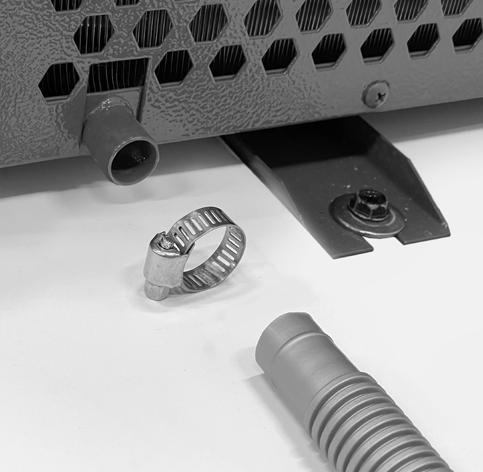
Install condensation hose
The CLIM8ZONE TM unit (figure 14, A) has a condensation drain spout as shown here.

1 Install the hose and hose clamp over the drain spout as shown here.
A hose clamp and condensation hose are supplied for drainage.
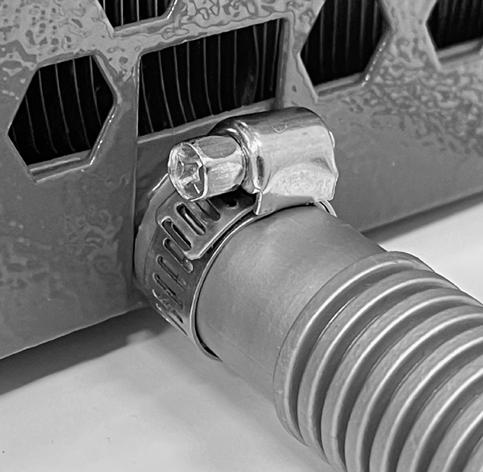

As much as 3+ liters of condensation per hour may flow from the end of the hose. Make sure the end of the hose has proper drainage, so water does not collect around the CLIM8ZONE TM unit. Condensation is normal and is not a water leak.
2 Tighten the hose clamp with a Philips head screw driver to secure the hose in place and create a water tight fit.
info@balboawater.com
P : + 714.384.0384
Customer Service is available: M - F 7:00AM to 6:00PM PT
Balboa Water Group
3030 Airway Avenue
Costa Mesa, CA 92626
MEXICO OPERATIONS
Balboa Water Group
Aguila Azteca 6011
Baja Maq. El Aquila
Mexico 22221
EUROPEAN OPERATIONS
Balboa Water Group
Hydroair International
ApS Roustvej 50 DK-6800
Varde