3 minute read
6 Spray System


Prerequisites The machine must be able to start in order to troubleshoot the spray system. If the machine does not start, see engine starting troubleshooting.
Components The electrical components of the spray system consist of: Pump Pump timer module Spray system switch
Sequence When troubleshooting the spray system, do so in the following sequence: 1.Check power to the pump. 2.Check the pump timer module. 3.Check the spray system switch.
6.2 Checking Power to the Spray Bar Pump
Prerequisites Seat platform in raised position. See section Rear Frame Access.
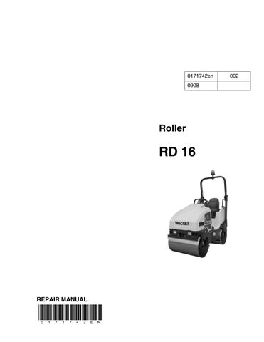
Procedure Follow the procedure below to check power to the spray bar pump. 1.Disconnect the wiring from the water pump (a).
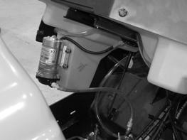
2.Place the key switch in the ON position. 3.Place the spray system switch in the ON position. 4.Measure the voltage at the connector (b).
Is more than 9.8V measured?
Yes ____ No ____
The pump has failed; replace it. See section Checking Power to Pump Timer Module.
The procedure for checking the power to the spray bar pump is now complete.
6.3 Checking the Pump Timer Module
Background The pump timer module is fed power in two locations: Via key switch on pink wire #01 Via spray system switch on pink wire #18
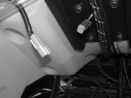
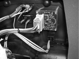
Procedure Follow the procedure below to check power to the pump timer module. 1.Remove the control console cover (a).
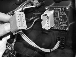
2.Disconnect the pump timer module connector (b). 3.Measure the voltage between pink wire #01 (connector pin 1) and ground. Is more than 9.8V measured?
Yes ____ No ____
Continue Repair or replace pink wire #1. 4.Place the key switch in the ON position. 5.Place the spray system switch in the ON position. 6.Measure the voltage between pink wire #18 (connector pin 11) and ground. Is more than 9.8V measured?
Yes ____ No ____
The pump timer module is receiving power and should be working; continue. Repair or replace pink wire #18.
7.Reconnect the pump timer module connector. 8.Measure the voltage between pink wire #18 (backprobe connector pin 6) and ground. Note: The voltage will be intermittent depending on the setting of the pump timer dial. Is more than 9.8V measured?
Yes ____ No ____
The pump timer module is functioning. The pump timer module has failed; replace it.
9.Re-install the control console cover.
The pump timer module has now been checked.
6.4 Checking the Spray System Switch
Background The spray system switch is fed power via the key switch on pink wire #29. When in the ON position, the spray system switch allows power to the pump control timer via pink wire #18.
Procedure Follow the procedure below to check the spray system switch. 1.Remove the control console cover (a).
2.Place the key switch in the ON position. 3.Measure the voltage between the incoming side of the spray system switch (b) (pink wire #29) and ground. Is more than 9.8V measured?
4.Place the spray system switch in the ON position. 5.Measure the voltage between the outgoing side of the spray system switch (pink wire #18) and ground. Is more than 9.8V measured?
The spray system switch has now been checked.
Yes ____ No ____
Continue Check the continuity of pink wire #29. Repair or replace pink wire #29.
Yes ____ No ____
The spray system switch is functioning. The spray system switch has failed; replace it.