9 minute read
4 Drive System


4 Drive System 4.1 Drive System Overview
Background The hydraulic system is powered by two pumps (exciter and drive) mounted in tandem—connected along their shafts through a solid-mounted coupling—and driven directly by the engine crankshaft through a flex coupling.
Drive pump The drive pump is a variable displacement, axial piston pump and includes an integral charge pump. Flow through the drive pump is controlled by varying its displacement through the movement of the control lever coupled to the pump’s control shaft. This allows a full range of operating speeds in both forward and reverse.
Drive motors There are two drive motors—one mounted to each drum. The drive motors are plumbed in series. Each drive motor is equipped with Spring Activated Hydraulically Released (SAHR) brake.
System filters and strainers
The hydraulic tank is equipped with a strainer at the fill port to trap large objects or particles which may accidentally fall into the tank while adding hydraulic fluid. Additional system protection is provided by a suction filter mounted in-line with the exciter pump inlet. The hydraulic system is protected by a return-line filter which removes dirt particles down to 10 microns and includes a flow bypass for cold weather start-up.
Troubleshooting sequence
When troubleshooting drive system problems, do so in the following sequence: 1.Check the function of the drive control cable. 2.Check the brake release solenoid valve. 3.Pressure test the drive pump and relief valve. 4.Check the drive motors.
4.2 Adjusting the Drive Control Cable
Background If the roller tends to drift in either direction when the forward/reverse control is in NEUTRAL, the drive control cable (a) must be adjusted.
Prerequisites Machine on a hard, level surface Engine running Forward/reverse control in the NEUTRAL position
Procedure Follow the procedure below to adjust the drive control cable. 1.Loosen the lock nut (b).
2.Move the turnbuckle (c) as needed until machine movement stops. If adjusting the turnbuckle does not achieve the desired results, a gross adjustment can be made at the nut (d) and then fine-tuned as described above.
The drive control cable has now been adjusted.
b a
d
c
wc_gr004121
4.3 Checking the Brake Release Solenoid Valve
Background The brake release valve controls hydraulic pressure to the brakes. If this solenoid valve is disconnected or malfunctioning, the brakes will not release and the machine will not move.
Prerequisites Drums chocked Assistant
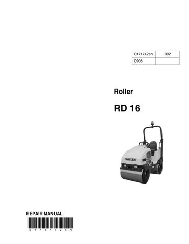
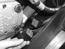
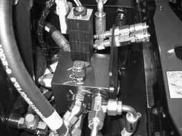
Procedure Follow the procedure below to check the brake release valve. 3.Open the engine compartment and locate the brake release valve (a).
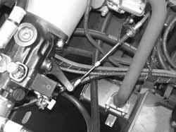
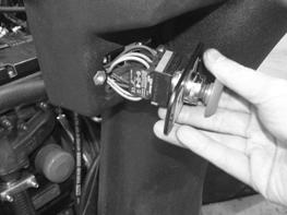
4.Remove the nut that secures the solenoid to the valve and slide the solenoid (b) from the valve. 5.Start the engine—the operator must remain seated in the operator’s seat. 6.Place the brake switch in the OFF position. 7.Check the magnetic force created by the solenoid by having an assistant place a piece of ferrous metal such as a screwdriver (c) inside the solenoid.
wc_gr004632
wc_gr004633 Does the solenoid magnetically attract the screwdriver? This procedure continues on the next page.
Yes ____ No ____
The solenoid is functioning. Continue.
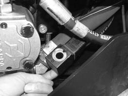
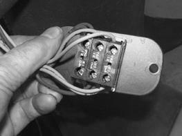
Continued from the previous page. 8.Remove the wiring connector (d) from the solenoid.
9.Check the voltage at the wiring connector (with the engine running, operator seated, and brake switch in OFF position). Is at least 9.8V measured?
The brake release valve has now been checked.
Yes ____ No ____
The solenoid has failed; replace it. Check the function of the brake switch.
4.4 Checking the Brake Switch
Prerequisites Machine shut down
Procedure Follow the procedure below to check the brake switch. 1.Remove the screws that secure the brake switch to the console. 2.Pull the brake switch (a) from the console.
3.Place the brake switch in the ON position (in). 4.Check for continuity across the terminals of the brake switch. There should be continuity across terminals “–1 NC” and “–2 NC” of each module and no continuity across terminals “–3 NO” and “–4 NO”. Is there continuity as stated above?
5.Place the brake switch in the OFF position (out). 6.Check for continuity across the terminals of the brake switch. There should be no continuity across terminals “–1 NC” and “–2 NC” of each module and continuity across terminals “–3 NO” and “–4 NO”. Is there continuity as stated above?
The brake switch has now been checked.
Yes ____ No ____
Continue. The brake switch has failed; replace it.
Yes ____ No ____
The brake switch is OK. Any problems with voltage reaching the brake solenoid are in the wiring to the solenoid. The brake switch has failed; replace it.
4.5 Checking the Drive System Operating Pressure
Prerequisites Machine on a firm, level surface 200-bar (3000-psi) pressure gauge Hydraulic oil warm
Background Failure of the drive circuit to reach operating pressures is normally caused by a worn or damaged drive pump; however, the problem could also be the result of a badly worn motor.
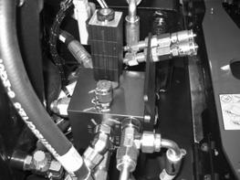
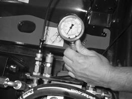
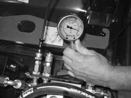
Procedure Follow the procedure below to test the drive system operating pressure. 1.Install a 200-bar (3000-psi) gauge in the forward test port (a).
2.Start the engine and run the machine at full throttle. 3.Shift the control lever to the FORWARD position and record the pressure on the gauge. The pressure should spike at approximately 97 bar (1400 psi) then settle into an operating pressure range of 55–76 bar (800–1100 psi). Note: Operating pressures will increase significantly when running the machine uphill, off road, or against an object. 4.Turn off the engine. 5.Install the 3000-psi gauge in the reverse test port and repeat the procedure while operating in reverse. Operating pressure lower than those listed indicate a failing drive motor. Higher pressures than those listed indicate a problem with the drive motors.
The drive system operating pressure has now been checked.
a 55 bar 800 psi
wc_gr004620
4.6 Checking the Drive System Relief Pressure
Prerequisites Machine on a firm, level surface 5000-psi pressure gauge
Procedure Follow the procedure below to check the drive system relief pressure. 1.Place blocks in front of and behind both drums to prevent the machine from moving, or dead head the machine against a solid concrete abutment. 2.Place the brake switch in the OFF position.
CAUTION! Crushing hazard. Use extreme caution when working near a running engine.
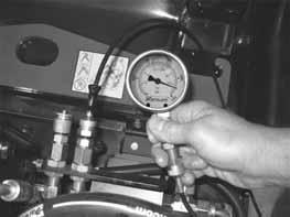
3.Install a 5000-psi gauge in the forward test port (a).
4.Start the engine and run the machine at full throttle. 5.Shift the forward/reverse control slowly into forward until pressure on the gauge tops out. This is the forward relief valve pressure. Note: Make sure the drums do not spin. 6.Stop the engine. 7.Install the gauge in the reverse test port (b) and repeat the procedure while operating in reverse.
The drive system relief pressure has now been checked.
4.7 Checking the Drive Motors
Prerequisites Graduated container Assistant
Background The drive motors are plumbed in series. When driving forward, hydraulic oil flows to the front drive motor first, then, on to the rear drive motor. When driving backward, hydraulic flow is just the opposite.
Procedure Follow the procedure below to check the drive motors.
1.Place blocks in front of and behind both drums to prevent the machine from moving, or dead head the machine against a solid concrete abutment. 2.Place the brake switch in the OFF position. 3.Start the engine and allow the hydraulic oil to warm up. 4.Turn off the engine. 5.Remove the case drain hose (a) from the front drive motor and plug the drive hose.
6.Start the engine. 7.Slowly place the forward/reverse control in the FORWARD position. Hydraulic oil will flow from the case drain port of the drive motor. 8.Have an assistant place a graduated container (b) underneath the drive motor to collect the hydraulic oil. Collect the hydraulic oil for one minute. 9.Turn off the engine.
WARNING! Crushing hazard. Use extreme care when conducting this test.

This procedure continues on the next page.
Continued from the previous page. Was more than four liters (1 gal.) of hydraulic oil collected?
Yes ____ No ____
The drive motor has failed; replace it. Continue. 10.Reconnect the case drain hose.
Note: If you measured less than four liters (1 gal.) but still suspect a drive motor problem, do the following: Place a 2x4 or similar piece of wood (equal to the width of the drum) in front of the drum. Attempt to drive over it. If the machine cannot drive over the piece of wood, consider replacing the drive motors. The drive motors have now been checked.
4.8 Manually Releasing the Parking Brakes
Background There are two drive motors on the roller—one on each drum. Each drive motor includes a parking brake that is spring activated and hydraulically released (SAHR).
Procedure To manually release the brakes, carry out the following procedure. NOTICE: To avoid damaging the internal mechanism, do not use power tools to release or reactivate the brakes.
Note: Carry out procedure on both drums. 1.Chock each drum to prevent the machine from moving. 2.Lock the articulated steering joint. 3.Using an 8mm Allen wrench, remove the plugs (a) in order to access the release screws (b).
a b d
c
wc_gr002964 4.Using a 6mm Allen wrench, press and turn each release screw in until its threads catch in the brake plate (d). Tighten each screw alternately until the spring (c) on each screw is fully compressed. You will feel a substantial difference in the amount of torque required to turn the screw once its spring is fully compressed. 5.Continue to tighten (turn clockwise) the two release screws to compress the brake plate springs. Alternate back-and-forth between the two screws, turning approximately 45° at a time, until the drums are no longer held by the brake plate. The brake plate should release after turning each screw approximately two (2) turns. NOTICE: Maximum torque for the release screws is 33 Nm (24.3 ft.lbs.). Overtightening the release screws can destroy the internal mechanism. 6.Manually turn the drum to test if the brake is released. 7.Replace the plugs (a), tightening them to a maximum torque of 60 ± 6 Nm (44.2 ± 4.4 ft.lbs.).
To reactivate the brakes, carry out the following procedure on both drums. 1.Remove the plugs (a).
This procedure continues on the next page.
Continued from the previous page. 2.Alternating betwen the two release screws (b), completely loosen them until the brake plate is disengaged. 3.Replace the plugs, tightening them to a maximum torque of 60 ± 6 Nm (44.2 ± 4.4 ft.lbs.). Note: Replacement drive motors come with the brakes engaged.