7 minute read
5 Vibration System


5 Vibration System 5.1 Vibration System Overview
Both the vibration and steering system share the same open loop, series circuit, driven by a fixed displacement, gear-type pump (exciter pump). The system includes separate relief valves for vibration and steering, an exciter control valve exciter motor, steering valve, steering cylinder, and cooling fan.
Vibration circuit
The exciter pump pulls oil from the tank through the suction filter and sends it to the exciter manifold block. The vibration circuit is controlled by the exciter solenoid valve. This valve is electrically operated by an ON/OFF switch located on the end of the forward/reverse control lever. The vibration circuit has two modes: singledrum and dual drum. Supply oil from the exciter pump is directed to the exciter control valve. When the ON/OFF switch is in the OFF position, the exciter control valve is open, allowing oil to pass downstream to the cooling fan and to the steering valve without driving the exciter motor. When the ON/OFF switch is in the ON position, power is sent to one of two solenoid valves depending on the position of the vibration mode switch. Hydraulic oil flows to the front drum or both drums accordingly. A relief valve connected across the exciter control valve limits pressure to 290 bar (4200 psi).
Steering circuit
Steering is controlled by a steering valve and cylinder. The steering wheel is splinemounted directly to the steering valve. The steering valve reacts to the motion of the steering wheel to direct oil to and from the steering cylinder. Oil returning from the vibration circuit is directed to the steering valve. If steering is inactive, oil passes through the steering valve and back to the return-line filter manifold. When the steering wheel is turned, the steering valve closes and directs oil to the appropriate steering line to extend or retract the cylinder. A relief valve is connected across the steering valve and is set at 45–51 bar (650–725 psi). Relief valves are also connected to each end of the steering cylinder. Each of these relief valves is also set at 45–51 bar (650–725 psi). The oil returning from the vibration and steering functions is directed back to the tank through a return-line filter. A filter bypass relief valve, set at 1.7 bar (25 psi), protects the return-line filter by routing oil past the filter if the filter is clogged.
Troubleshooting sequence
When troubleshooting: For systems that vibrate poorly, see section Troubleshooting a System that
Vibrates Poorly. For complete vibration system failure, see sections Checking the Vibration
Solenoid Valve and Checking the Vibration Switch.
5.2 Checking the Engine Speed and Vibration Speed
Prerequisites Vibrotach Vibration must turn on
Procedure Follow the procedure below to check the engine rpm and drum vpm. 1.Start the engine and place the throttle switch in the FAST position. 2.Measure the engine rpm using a vibrotach.
3.Measure the vpm (vibrations per minute) by placing the vibrotach on the rim of the drum while vibration is on. 4.If the vpm is not 4150–4250, adjust the throttle linkage (a) until it is. If vpm cannot be obtained by adjusting the linkage, adjust the stop screw (b).
The procedure to check the engine rpm and drum vpm is now complete.
5.3 Troubleshooting a System that Vibrates Poorly
Prerequisites 5000-psi pressure gauge Compactible surface such as a bed of gravel or old tires
Background The exciter pump is designed to put out a constant flow of oil at a set engine speed. This ensures that the vibration frequency remains steady. When troubleshooting the exciter circuit, the vibration speed, operating pressure, and relief pressures must be known to help determine the cause of any problems.
Procedure To measure vibration speed: 1.Start the machine and run it for several minutes to bring the hydraulic fluid up to normal operating temperature. 2.Drive the machine onto a compactible surface such as a bed of gravel or old tires. 3.Run the machine at full throttle. Check the engine rpm using a tachometer or vibrotach. 4.Start vibration. Hold the vibrotach (P/N 53397) against the outer rim of the drum and measure the vibration speed.
Engine rpm Vibration Frequency vpm Operating Pressure Single Drum Mode bar (psi)
Operating Pressure Dual Drum Mode bar (psi) 2850* 4200 103–131 (1500–1900) 138–165 (2000–2400)
*Adjust engine rpm if necessary to obtain 4200 vpm.
5.Shut down the machine.
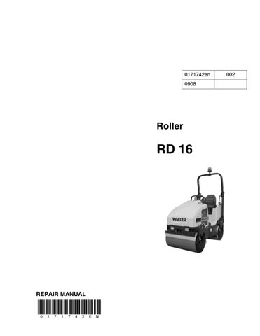
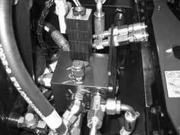
To check vibration system operating pressure: 1.Open the engine compartment. 2.Locate the exciter solenoid valve (a).
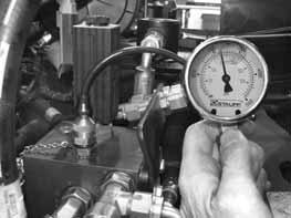
3.Connect a 5000-psi gauge to the test port (b).
This procedure continues on the next page.
Continued from the previous page. 4.Start the engine and run the machine at full throttle. 5.Turn on the vibration and measure the relief and operating pressures. The relief pressure is the pressure registered on the gauge as soon as the vibration is turned on. The system will then settle into operating pressure. Record these two pressures. 6.Shut down the machine.
Compare the results from operating pressure, pump relief pressure, and exciter speed with the chart below.
Operating Pressure Pump Relief Pressure Exciter Speed Probable Cause
N N N System OK
H N N or L Exciter bearings or motor binding N or L N L Exciter motor worn
L L L Exciter pump damaged or worn, relief valve defective, or needs adjusting
N = Normal, L = Low, H = High
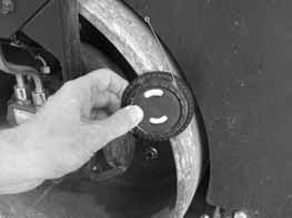
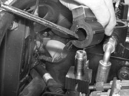
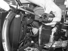
If the exciter is binding or causing high operating pressures, perform the following: 1.Disconnect the hydraulic hoses (c) and remove the exciter motor (d) from the housing.
2.Turn the motor shaft and exciter shaft by hand and check that they both turn freely. 3.If either component does not turn freely, it has failed; replace it.
The vibration system has now been checked for poor vibration.
c
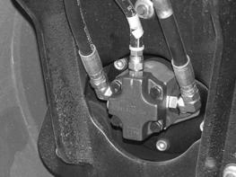
d
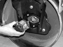
wc_gr004622
5.4 Checking the Vibration Solenoid Valve
Prerequisites Multimeter Assistant
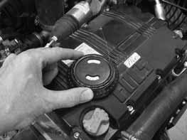
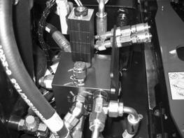
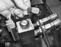
Background There are two solenoids mounted to the vibration manifold. One controls hydraulic oil flow for dual-drum vibration and one for single-drum vibration. The lower solenoid (a) controls single-drum vibration. The upper solenoid (b) controls dual-drum vibration. To check the function of the vibration electrical system, both vibration solenoids and the vibration switch should be tested.
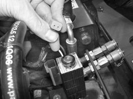
Procedure Follow the procedure below to check the vibration solenoids. 1.Remove the nut (c) that secures each solenoid and remove the upper solenoid from the valve stem.
2.Have an assistant sit in the operator’s seat. 3.Turn the key switch to ON. Do not start the engine. 4.Have the assistant activate the vibration using the vibration switch on the forward/reverse control lever. 5.Check the magnetic force created by the solenoid by placing a piece of ferrous metal such as a screwdriver (d) inside the solenoid.
Does the solenoid magnetically attract the screwdriver?
This procedure continues on the next page.
Yes ____ No ____
The solenoid is functioning. Continue.
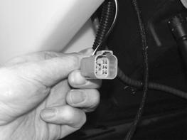
Continued from the previous page. 6.Remove the connector (e) from the solenoid.
7.Check the voltage at the wiring connector. Is at least 9.8V measured?
Yes ____ No ____
The coil of the solenoid has failed: replace it. Check the function of the vibration switch.
8.Reconnect and reassemble the solenoid. 9.Check the lower solenoid in the same manner.
The vibration solenoids have now been checked.
5.5 Checking the Vibration Switch
Background When the roller’s engine is running, the solenoid of the vibration manifold receives power through the white wire via the vibration switch. To check the function of the vibration electrical system, both the vibration solenoid and the vibration switch should be tested.
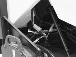
Procedure Follow the procedure below to check the vibration switch. 1.Remove the four screws that secure the seat platform. Then, raise the platform. 2.Locate the connector (a) for the vibration switch and disconnect it.
3.Press the switch several times while checking for continuity between the pins of the connector (two black wires). Does the switch open and close?
Yes ____ No ____
The vibration switch is OK. The vibration switch has failed; replace it. 4.Reconnect the wiring.
The vibraton switch has now been checked.