6 minute read
3 Engine Start System Troubleshooting


Prerequisites Before troubleshooting engine starting issues, check the battery and the cable connections to the battery. The battery must be fully charged (approximately 12V).
Sequence Complete the troubleshooting in the following sequence: 1.Check the wiring to the starter solenoid. 2.Check the 30A main fuse. 3.Check the key switch. 4.Check the crank relay. 5.Check the neutral switch. 6.Check the neutral relay.
3.1 Checking the Wiring to the Starter Solenoid
Prerequisites Machine shut down
Background Black wire #66 delivers 12VDC to the starter solenoid. If this wire is broken or disconnected, the engine will not start.
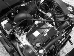
Procedure Follow the procedure below to check the wiring to the starter solenoid. 1.Open the hood and locate the starter solenoid (a).
2.Check the connection and condition of black wire #66. Is the wiring OK?
Yes ____ No ____
Continue Reconnect or repair black wire #66.
The wiring to the starter solenoid has now been checked.
3.2 Checking the 30A Main Fuse
Prerequisites Machine shut down
Background There are three fuses that protect the circuitry on the RD 16: 30A lights 30A main 20A throttle pull
Procedure Follow the procedure below to check the 30A main fuse. 1.Open the hood and locate the fuse carrier.
2.Remove the protective cover from the fuse carrier (a). 3.Check the condition of the 30A main fuse (b). Is the 30A fuse OK?
Yes ____ No ____
Continue Replace the 30A fuse with one of same size and rating. 4.Re-install the protective cover to the fuse carrier.
The 30A fuse has now been checked.
3.3 Checking the Key Switch
Prerequisites Multimeter Fully-charged (approximately 12V) battery Functioning main fuse
Background The key switch is a three-position switch: ON, START, and OFF. When in the START position, the key switch directs battery voltage to the crank relay.
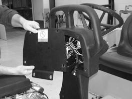
Procedure Follow the procedure below to check the key switch. 1.Remove the screws that secure the plate (a) to the back of the control panel and remove the plate.
2.Using the multimeter, check the voltage between the BAT terminal (b) of the key switch and ground. For easier measuring, remove the plug and measure voltage at the plug. Is battery voltage (approximately 12V) measured?
Yes ____ No ____
Continue Check the continuity of red wire #33 between key switch and 30A main fuse. Repair red wire #33 as needed.
Yes ____ No ____ The key switch is not the problem. The key switch has failed; replace it.
3.Place the key switch in the START position.
4.Check the voltage between the “S” terminal (c) of the key switch and ground. Is battery voltage (approximately 12V) measured?
5.Re-install the plate to the back of the control console. The key switch has now been checked.
3.4 Checking the Crank Relay
Prerequisites Multimeter Fully-charged (approximately 12V) battery Functioning main fuse Functioning key switch
Background The coil of the crank relay is energized when the key switch is in the START position.
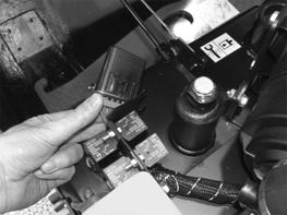
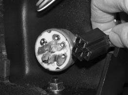
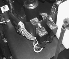
Procedure Follow the procedure below to check the crank relay. 1.Open the hood and locate the crank relay (a).


2.Check the voltage between terminal 30 (red wire #32) and ground. This test may be done at plug (b) with it disconnected from the crank relay. Is battery voltage (approximately 12V) measured?
Yes ____ No ____
Continue Repair red wire #32. 3.With the key switch in the START position, check the voltage between terminal 86 (black wire #34) and ground. This test may be done at plug (b) with it disconnected from the crank relay. Is battery voltage (approximately 12V) measured?
Yes ____ No ____
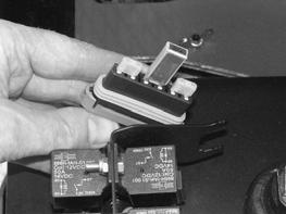
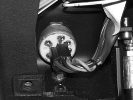
Continue Repair black wire #34. 4.With the key switch in the START position, check the voltage between terminal 87 and ground (pink wire #60). For this test, plug (b) must be connected to the crank relay. Position the plug as shown to allow access to terminal 87. Is battery voltage (approximately 12V) measured?
The crank relay has now been checked.
Yes ____ No ____
The crank relay is OK. The crank relay has failed; replace it.
3.5 Checking the Neutral Switch
Prerequisites Multimeter Fully-charged (approximately 12V) battery Functioning main fuse Functioning key switch Seat platform in raised position. See section Rear Frame Access.
Background The neutral switch, when closed (control lever in NEUTRAL position), allows voltage to the neutral relay.
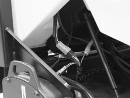
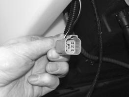
Procedure Follow the procedure below to check the neutral switch. 1.Locate the connector (a) for the neutral switch and disconnect it.
2.Place the control lever in the NEUTRAL position. 3.With the key switch in the START position, check the continuity between the pins of the connector (green and white wires). Is there continuity?
4.Place the control lever in the FORWARD or REVERSE position. 5.With the key switch in the START position, check the continuity between the pins of the connector (green and white wires). Is there continuity?
Yes ____ No ____
Continue The neutral switch has failed; replace it.
Yes ____ No ____
The neutral switch has failed; replace it. Continue 6.Repeat the test with the control lever in the REVERSE position. Is there continuity?
Yes ____ No ____
The neutral switch has failed: replace it. The neutral switch is OK. 7.Reconnect the wiring. 8.Lower and secure the seat platform. The neutral switch has now been checked.
3.6 Checking the Neutral Relay
Prerequisites Multimeter Fully-charged (approximately 12V) battery Functioning main fuse Functioning crank relay Functioning neutral switch
Background The neutral relay relays battery voltage to the starter solenoid.
Procedure Follow the procedure below to check the neutral relay. 1.Open the hood and locate the neutral relay (a).
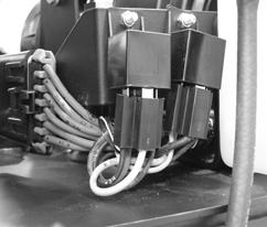
2.Place the key switch in the START position. 3.Check the voltage between terminal 30 (pink wire #60) and ground. This test may be done at plug (b) with it disconnected from the neutral relay. Is battery voltage (approximately 12V) measured?
Yes ____ No ____
Continue Repair pink wire #60.
This procedure continues on the next page.
Continued from the previous page.
4.Check the voltage between terminal 86 (green wire #61) and ground. This test may be done at plug (b) with it disconnected from the neutral relay. Is battery voltage (approximately 12V) measured?
Yes ____ No ____
Continue Repair red wire #31. 5.Check the voltage between terminal 87 (black wire #66) and ground. For this test plug (b) must be connected to the crank relay. Position the plug as shown to allow access to terminal 87. Is battery voltage (approximately 12V) measured?
Yes ____ No ____
The neutral relay is OK. The neutral relay has failed; replace it. The neutral relay has now been checked.