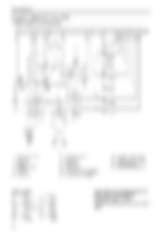
Wiring diagrams
Engines: TAMD71B* (12 V, 24 V) * As from. engine No. 207181084/xxxx.
1. 2. 3. 4. 5. 6. 7a. 7b.
Batteries (12 V, 24 V) Main switch Starter motor Alternator Fuel shut-off valve Fuse (8 A) Stop relay Starter relay
8. 9. 10. 11. 12. 13. 14. 15.
Cable colour BL LBL BN LBN GN GR OR 10
= = = = = = =
Blue Light blue Brown Light brown Green Grey Orange
P PU R SB VO W Y
= = = = = = =
Pink Purple Red Black Violet White Yellow
Circuit breakers (8 A) Earthing point Timer relay Fuse (150 A) Starting heater Oil pressure sensor, reverse gear Pressure sensor, charge pressure Oil pressure sensor, engine
16. 17. 18. 19. 20.
Oil pressure monitor, engine Coolant temperature sensor Coolant temperature monitor Engine speed sensor Connector, instrument panel
Cable areas (mm²) are specified after the colour code in wiring diagrams. Unspecified areas = 1.0 mm². A broken line indicates a non Volvo Penta cable.
