5 minute read
Draining Engine Block or Exhaust Manifold

5.0GXi-A/B, 5.7Gi-A/B, 5.7GXi-B/C
Draining the cooling system – raw water
Advertisement
1.Locate the engine flush connector (1) at the front of the engine refer to features pages for location of flush adapter. Connect a garden hose to the connector with the supplied adapter.
NOTE! The hose connection adapter supplied with the engine may not work in all geographic locations.
Caution!
Do not run the engine during the flushing procedure. Water is not supplied to the raw water pump and the pump impeller will be damaged.
2.Turn the fresh water supply on and flush the engine with fresh water for 5 minutes to ensure the drain ports are open.
3.Turn off the fresh water supply and disconnect the garden hose from the engine flush connector. Lower the engine flush hose below the engine level and let drain.
4.After all of the water has drained out, reattach the hose cap and place back in original location.
5.Remove drain plugs from the exhaust manifold(s) and let drain completely. Reinstall the drain plug(s) and tighten.
Caution!
If a garden hose with fresh water supply is unavailable, you must remove the hose nipple(s) from the engine to drain the engine block. To ensure all water is drained, clear the drain hole with a piece of wire. After the engine is drained reinstall the hose nipples and flush adapter as removed. The exhaust manifolds are drained as described previously
5.0GXi-B/C/D/E, 5.0OSi-B/C/D/E, 5.7Gi-B/C/D/E, 5.7OSi-A/B/C/D, 5.7GXi-C/D/E, 5.7OSXi-A/B/C/D (F)series (closedcooling)
To drain the raw water side of the cooling system of your factory installed closed cooling on your Volvo Penta engine.
Caution! 5.0GXi-AF/BF/CF/DF/EF, 5.7Gi-AF/BF/CF/DF/EF, 5.7GXi-BF/CF/DF/EF/FF, OSi-AF/BF/CF/DF/EF, OSXi-AF/ BF/CF/DF engines come factory filled with 50/50 coolant mixture of propylene glycol an tifreeze and water. If the engine requires topping off, use only proylene glycol to refill the cooling system. Do not use Volvo Penta ethylene glycol in the cooling system.
If Volvo Penta antifreeze is pr eferred, you may use it provided the cooling system is dr ained and flushed before filling it wih Volvo Penta antifreeze.
Note!The boat should be out of the water and the bow down slightly to allow complete drainage.
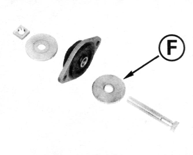
1.Using a 9/16 inch wrench, loosen but do not remove the cover bolt (1) on the bottom of the heat exchanger approximately three revolutions.
2.Twist the heat exchanger cover and gasket (2) in either direction and allow the water to completely drain from the system.
3.After the heat exchanger is drained, retighten the cover bolt to 27 N•m (20 lb. ft.)
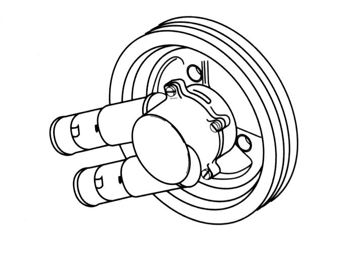
4.Loosen the hose clamp (3) on the raw water inlet hose and remove the hose from the raw water pump.
5.Allow all the water to drain and reinstall the hose and tighten the hose clamp.
Caution
Ensure there is sufficient anti freeze in the closed side of the cooling system to protect the engine for the anticipated temperatures. Follow the antifreeze manufacturers instructions for proper water/antifreeze ratios.
1.With the engine turned off, locate and open the engine drain petcocks (B) located on both sides of the engine block.
Caution!
Be sure that all water is dr ained from the engine. If no water drains when the petcocks are opened, remove the petcocks and use a piece of wire to clear any obstructions from the drain hole. Failure to drain all the water from the engine may result in engine damage during freezing temperatures.
2.Remove drain plugs from exhaust manifolds (A). Raise or lower the bow of the boat to ensure complete drainage. After the water has completely drained, reinstall the drain plugs and torque to 29 N•m (22 lb. ft.).
Draining Supply Pump
3.Note the hose orientation on the raw water pump. Loosen the hose clamps and remove the hoses from the raw water pump. Crank the engine briefly, (1 or 2 crankshaft revolutions) but do not start the engine, to clear the water from the pump. Reinstall the hoses and secure the clamps in the same orientation as removed.
Caution!
Failure to connect the raw water pump hoses in the correct orientation may damage the raw water pump impeller.
1.Loosen and slide hose clamps back. Remove hoses from the pump and drain.
2.Crank the engine no more than 2 seconds (DO NOT START) to expel any water trapped in water pump. Reattach hoses.
Thermostat Replacement
1.Remove all water hoses from the thermostat housing.
•GL Models: four hoses
•Gi and GXi Models: same as GL plus one, five hoses
2.Note position of lifting eye. Remove two screws then remove lifting eye and thermostat housing.
3.The thermostat is held in place by an O-ring. Pry the O-ring out of its groove, then lift the thermostat out of the housing.
4.Discard the housing gasket and O-ring. Thoroughly clean the housing and manifold gasket surfaces.
5.Place the thermostat in the housing. The temperature sensing element must face you when installed. Install a new O-ring to seal thermostat in housing. Make sure O-ring is completely seated in its groove.
6.Coat both sides of a new gasket with Volvo Penta Gasket Sealing Compound and place it on the manifold. Position thermostat housing and lifting eye on engine adapter as noted in Step 2. Install two lock washers and screws. Tight en the screws to 20-25 ft. lb. (2734 N•m).
7.Connect the water supply hose to nipple and tighten hose clamp securely. Connect the three remaining water hoses and tighten hose clamps securely. Make sure lifting eye is positioned as shown.
Caution!
If the water supply hose is attached to the wrong nipple, the engine will overheat.
Numbers refer to Cooling System Flow Diagrams.
1. Intake Screen - Blocked with debris.
2. Water Tube Guide and Seal - Improperly sealed.
3. Water Tube - Plugged with debris.
4. Grommet - Deteriorated, improperly seated.
5. Upper Gear Housing - Debris blocking pa ssage, freeze damaged.
6. Pivot Housing Seal - Damaged, out of position, improperly sealed.
7. Nipple O-ring - Out of position, improperly sealed, damaged.
8. Nipple - Blocked by debris, freeze cracked, loose in housing.
9. Water Hose and Clamps - Clamps loose, hose collapsed or leaking.
10. Transom Mount Water Tube - Blocked by debris.
11. Supply Pump (Engine Mounted) - Failed seal, corroded or bad bearings, eroded impeller, leaki ng mounting gaskets or backing plate.
12. Thermostat Housing - Corroded, restricted, or leaking gasket.
13. Thermostat - Defective thermostat, or wrong type for engine; improperly seated or damaged O-ring.
14. Belts - Loose, or worn and slipping.
15. Circulating Pump (Engine) - Failed seal, corroded or bad bearings, eroded impeller, leaking mount ing gaskets or backing plate.
16. Cylinder Block Water Passages - Corrosion, slag, blocked passages, or leaking core plugs.
17. Cylinder Head - Corrosion, slag, blocked passages or leaking gaskets.
18. Exhaust Manifold, Elbows, Gaskets, and Hoses - Gaskets improperly installed; corrosion, sand, or slag in manifold and elbows; hoses collapsed, burned through, or leaking.
19. Exhaust Pipe and Seal - Improperly sealed or installed, leaking.
20. Bellows, Clamp, and Retainer - Loose clamp, detached or torn bellows.
21. Power Steering Cooler - Restricted, or cracked and leaking.
22. Intake Manifold - Cracked casting, or leaking gasket(s).
23. Engine Oil Cooler - Restricted, or cracked and leaking.
In addition, check:
• Ignition Timing
• Boat Hull - Condition of hull, marine growth, or under- hull equipment.
Note!Fittings protruding through hull may cause air bubble streams which can be picked up by the lower gearcase and mixed with incoming cooling water to cause an overheat condition.