10 minute read
Section 6: Cooling System


Description
Raw Water Cooled Engines
Advertisement
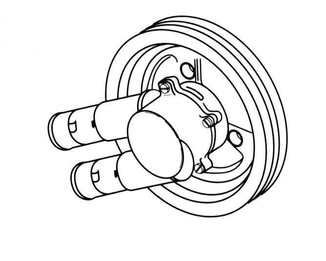
Raw water is supplied to the eng ine by means of an impeller type pump (raw water supply pump). The raw water supply pump is mounted on the engine crankshaft. Water supplied to the engine is circulated in the engine by means of a centrifugal type pump (circulating pump).
During low speed operation the impeller functions as a positive displacement pump. At higher speeds it functions as a combination centrifugal and positive displacement pump.
The shape of the housing and/or liner cause an eccentric action of the impeller blades during engine operation. During periods of high speed operation, the resistance of the water on its way through the pump is sufficient to prevent the ends of the impeller blades from making contact and following the inside perimeter of the pump housing. The blades merely flex in toward the center of the impeller to perform as a combination centrifugal and positive displacement pump.
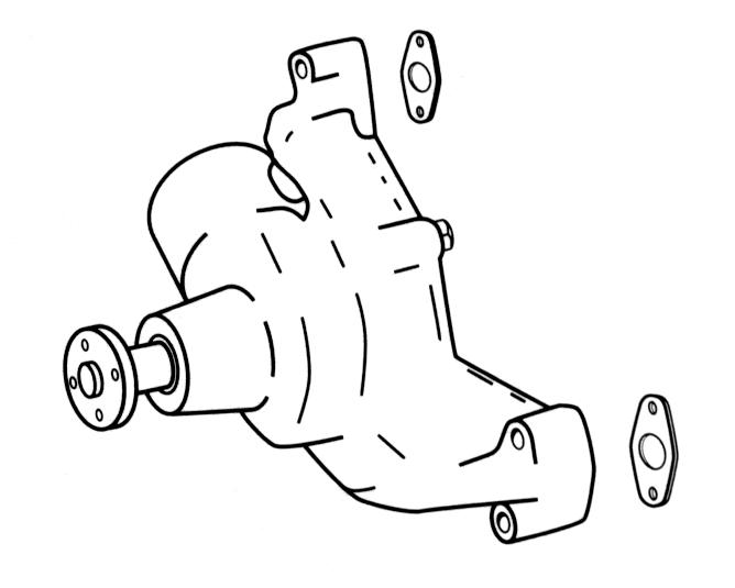
The circulating pump is mounted on the front of the cylinder block. It has a pulley bolted to the pump shaft hub at its forward end. This in turn is driven by means of a belt from the crankshaft pulley. The pump shaft and bearing assembly is pressed in the water pump housing. The bearing is permanently lubricated dur ing manufacture and sealed to prevent loss of lubricant and entry of dirt. The pump is sealed against coolant leakage by a non-adjustable seal assembly pressed into the pump housing.
Cooling water for the engine is picked up at the water intakes on both sides of the lower gearcase. Water is pulled upward through the lower gearcase until it enters a water tube that transfers it to the upper gear housing.
Water is pulled through the upper gear housing water passage where it meets a nipple and hose attached to the pivot housing. Water is routed through the transom mount assembly to a tube that’s mounted on the inside of the gimbal housing. From this tube the water is drawn through a supply hose that’s connected to the inside nipple of the supply pump. Water exits the outside nipple of the supply pump under pressure and carried through a hose to the inlet nipple of the thermostat housing.
The water is now carried downward through the thermostat housing where it enters the flexible hose which attaches to the inlet pipe of the circulating pump. This inlet pipe is a part of the pump cover and feeds the coolant into a low pressure area located at the axis of the impeller. Vanes on the rotating impeller cause the coolant to be thrown outward and into the cylinder block.
The cooling water flows rearward through the water jacket which surrounds each cylinder and ex tends below the lower limit of piston ring travel. After flowing the full length of the cylinder block, the water is forced upward through two passages and into the cylinder head(s). The water now flows forward in the cylinder head(s) to cool the combustion chamber areas.
At the forward end of the cylinder head(s), the water enters the thermostat housing. If the water within the block is sufficiently warmed up, the thermostat will be open and a portion of the water will be pumped upward past the thermostat. The remainder will be returned via the flexible hose to the water pump for recirculation within the engine. The water which was pumped upward past the thermostat will enter the hose(s) connected to the thermostat housing outlet(s) and travel to the exhaust manifolds.
At this point the water flows rearward through the manifold passages and into the high-rise elbow. All of the water that ente rs the high-rise elbow is mixed with the exhaust gas es prior to entering the exhaust pipe(s) and hose(s). This mixtur e of exhaust gases and water then enters the exhaust passages of the gimbal housing, pivot housing and sterndrive where it is discharged under water.
Closed Cooling Engines
In the event the engine cooling water is cold, as in first starting up, the thermostat will be closed and will not allow any of the water to pass through for eventual discharge over board. Instead, the water will be carried via the flexible hose back to the circulating pump for recirculation within the block. While the water within the block is recirculating, the supply pump is pumping water to the block.
Since this water is not able to enter the cylinder block, it is necessary to provide a method of discharge. Th is is provided by the bypass passage within the thermostat housing. If this were not provided, the resulting water pressure would be enough to force the thermostat off its seat, resulting in a greatly increased warm-up period.
The closed cooled engine is split into two halves by a heat exchanger, a raw water side and a closed cooled side of the heat exchanger. The heat exchanger transfers heat remov ed from the closed cooled side of the system to the raw water side which is pumped overboard through the exhaust.
Raw Water Side
Raw water is supplied to the heat exchanger by means of an impeller type pump (raw water supply pump) . The raw water supply pump is mounted on the engine crankshaft. During low speed operation the impeller functions as a positive di splacement pump. At higher speeds it functions as a combination cent rifugal and positive displacement pump. The shape of the housing and/or liner cause an eccentric action of the impeller blades during engine operation. During periods of high speed operation, the resistance of the water on its way through the pump is sufficient to prevent the ends of the impeller blades from making contact and following the inside perimeter of the pump housing. The blades merely flex in toward t he center of the impeller to perform as a combination centrifugal an d positive displacement pump.
Raw water for the heat exchanger is picked up at the water intakes on both sides of the lower gearcase. Water is pulled upward through the lower gearcase until it enters a water tu be that transfers it to the upper gear housing.
Water from the raw water pump is supplied to the heat exchanger and is circulated through several channel s inside the heat exchanger at which point it exits through flexible hoses to the exhaust manifolds. At this point the water flows rear ward through the exhaust manifold passages and up into the high-rise elbow. All of the water that enters the high-rise elbow is mixed with the exhaust gases prior to entering the exhaust pipe(s) and hose(s). Th is mixture of exhaust gases and water then enters the exhaust passages of the gimbal housing, pivot housing and sterndrive where it is discharged under water.
Closed Cooling Side
The closed cooling side of the heat exchanger contains the water and antifreeze mixture and transfers engi ne heat from the coolant to the raw water circulated through the exchanger.
The closed cooling side of the heat exchanger flows through the engine circulation pump. The engine circulating pump is mounted on the front of the cylinder block. It has a pulley bolted to the pump shaft hub at its forward end and is driven by a belt from the crankshaft pulley. The pump shaft and bearing asse mbly are pressed in the water pump housing. The bearing is perman ently lubricated during manufacture and sealed to prevent loss of lubricant and entry of dirt. A nonadjustable seal assembly pressed into the pump housing seals the pump against coolant leakage.
The coolant flows rearward from th e circulating pump through the cooling jacket, which surrounds each cy linder and extends below the lower limit of piston ring travel. After flowing the full length of the cylinder block, the coolant is forced upward through two passages and into the cylinder head(s). The water now flows forward in the cylinder head(s) to cool the combustion chamber areas.
At the forward end of the cylin der head(s), the coolant enters the intake manifold and the thermostat housing. If the coolant within the block is sufficiently warmed up, the thermostat will be open and a portion of the coolant will be pumped upward past the thermostat. The remainder will be returned via the flex ible hose to the circulating pump for re-circulation within the engine. The coolant, which was pumped upward past the thermostat, will enter the Heat Exchanger to transfer engine heat to the raw water side of the cooling system. At this point the process starts over.
Cooling System Troubleshooting
Quiz Customer for the Following Information: a.How old is unit, how many hours of operation? (Wear and corrosion.) b.How long has problem exis ted? (Gradual or sudden.) c.What were the operating conditions prior to problem? (Fresh or salt water, silty or sandy water.) d.What previous repairs and se rvice have been made on unit? (Tune-ups, impeller replacement, etc.) e.At what RPM does problem occur? (Low, high.)
Possibilities To Consider: a.Temperature Gauge Malfunction.
•Improper or defective sender unit b.Engine Water Circulation Pump Malfunction.
•Malfunctioning gauge - Check ground wire - substitute good gauge.
•Loose alternator belt c.Water Intake Screens Blocked. d.Ventilation - Marine growth on keel, hull deformities, etc. e.Ignition Timing
•Impeller vanes worn - replace pump.
•Impeller shaft seal failure - replace pump.
•Running with retarded timing (carbureted engines only)Check timing.
Isolating Cooling Problem:
Air or exhaust gas entering cooling water: a. Procedure - Replace water hose between thermostat housing and the supply pump with clear pl astic hose. Operate unit in test tank or boat in water at RPM at which overheat occurs. b. Results and Conclusions - No bubbles in hose, air/ exhaust is not entering cooling water. Bubbles in hose, air/exhaust is entering cooling water. c. Check for - Defective lower gearcase water tube guide and seals; damaged water tube grom met; leaking water passage cover gasket or adaptor-t o-gear housing gasket.
NOTE! If operating unit in test tank, run motor in neutral. Some test tanks may not have sufficient water volume to allow running engine in gear without creating turbulence. This can be picked up by the water intake and misconstrued as evidence of a cooling problem.
Insufficient water supply: a. Procedure - Disconnect water supply hose from transom bracket at thermostat housing. Operate engine at specified idle RPM. Hold end of hose level with the top of the flame arrestor. b. Results and Conclusions - A 1 inch (2,5 cm) head of water discharge, water supply is good. If less than 1/2 inch (1.2 cm), look for source of water loss. c. Check for - Blocked intake screens; damaged impeller housing O-ring or impeller plate gasket; broken or worn impeller; defective pivot housing water passage O-ring or water drain screw seal; loose pivot housing-to-gimbal housing water hose clamps.
Thermostat malfunction a. Procedure - Operate engine until indicated temperature exceeds 160°F (71° C). Touch hoses between thermostat and exhaust manifolds. b. Results and Conclusions - Hoses cold, thermostat is stuck closed. Hoses warm or hot, thermostat is good. c. Check for - Thermostat stuck open or closed, defective thermostat O-ring, correct thermostat style for engine type, clear thermostat housing bypass passage.
Engine head gasket leakage a. Procedure - Allow engine to cool. Replace water hose(s) between thermostat housing and exhaust manifolds) with clear plastic hose. Operate unit at RPM at which overheat occurs. b. Results and Conclusions - No bubbles evident, head gaskets not leaking. Bubbles ev ident, head gaskets leaking. c. Check for - Cylinder compression using appropriate tester, water in engine oil, water in cylinders, spark plugs wet with water.
Cooling System Components
Hoses, Clamps, and Drain Plugs No special tools required.
Inspection Procedure: Examine all external cooling system components for leaks, wear, deterioration, and damage. Check all connections for tightness. Inspect hoses for cracks, checking or deterioration.
Repair Procedure: Repair or replace as required.
Water supply hoses used for replac ement must conform to S.A.E. 20R3, class D-2.
Thermostat
A 160° F (71° C) thermostat is standard.
Inspection Procedure: Check for proper rating and style, corrosion, restricted movement, or broken spring.
Test Procedure - Immerse the thermostat and a thermometer in a container of water. Heat water. Thermostat should start to open between 157-163° F (70-73° C), and should open to 5/32 in. (3,96 mm) minimum (A) at 182° F (83° C).
Repair Procedure: None, replace unit.
Manifolds and Elbows
No special tools required.
Inspection Procedure: Pressure check components for leaks. Disassemble and inspect for corrosion or accumulation of foreign material.
Repair Procedure: Rod out any accumulation of foreign matter built up in water passages. If evidence of porosity between water passages and exhaust chambers or exterior is found, replace component. Install new gaskets on reassembly.
Circulating Pump - Engine
No special tools required.
Inspection Procedure: Make sure belt tensio n is correct. With the engine running, observe the rotation of the circulating pump pulley. If the pulley does not run true it can c ause excessive drive belt wear and damage to the circulating pump itself.
If the leakage of water occurs at the circulating pump while the engine is in operation, the pump may be loosely mounted to the engine, the shaft seal in front of the pump may be bad, the backing plate gasket may be defective, or the circulat ing pump mounting gaskets are leaking.
If the above inspections do not de tect any defect, the pump must be removed and inspected for internal corrosion, blockage, or damage. Inspect impeller for erosion.
Repair Procedure: None, replace the pump.
NOTE!Volvo Penta marine engines have a special circulating water pump with stainless stee l components and a special marine shaft seal assembly. Do not replace with an automotive water pump. Supply
Removal
1.Drain engine, refer to Draining Engine Block or Exhaust Manifold on page202.
2.Loosen hose clamps and remove hoses from supply pump. Note: The upper hose is the inlet hose.
2.Remove pump housing.
3.Remove and discard O-ring.
4.Grasp impeller securely and pull from housing.
Cleaning and Inspection
1.Clean all parts with solvent and blow dry thoroughly.
2.Clean sealing surfaces.
3.Inspect impeller housing wear, and housing for cracks and distortion caused by freezing. Replace if necessary.
4.Inspect impeller; if blades are se t in a bent position, cracked or broken, or show flat instead of rounded edges on the housing contact surfaces, replace the impeller.
5.Check bearings for smooth operation.
Impeller Installation
1.Apply a light coat of glycerine to impeller surfaces. Install impeller until seated in the housing.
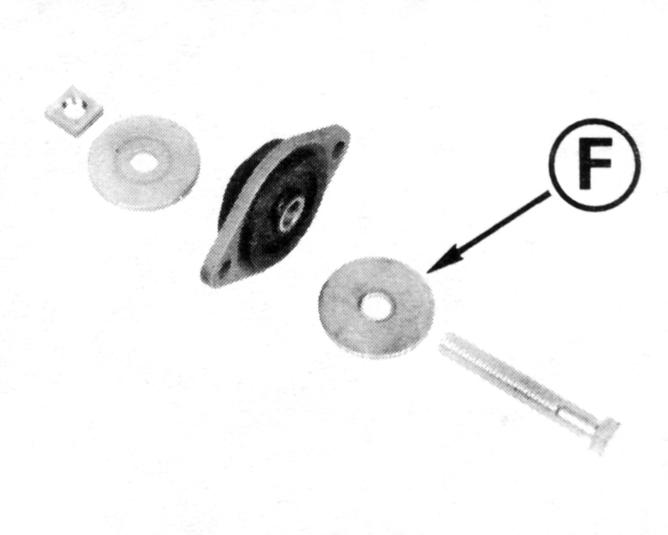
2.Apply a light coat of Volvo Penta Grease to a new O-ring. Install the O-ring onto the pulley and shaft assembly.
3.Install pump and secure with four screws. Tighten screws to 19-24 in. lb. (2,2-2,8 N•m).
4.Orient pump assembly. Install bracket and secure with screws. Tighten screws to 20-2 5 ft. lb. (27-34 N•m).
5.Attach the inlet hose to upper nipple and the outlet hose to the lower nipple. Tighten hose clamps securely.