8 minute read
Cylinder Installation


NOTE!If cylinder is being replaced due to fluid contamination, be sure to flush system of contamination before installing a new cylinder.
1.Install anchor screws flush with inside of inner transom bracket.
Advertisement
2.Apply Volvo Penta Grease to both bushings.
Caution!
Filling the bushing pockets full with grease can cause the screws to hydraulically lock and break the transom plate when tightened.
3.Position steering cylinder assembly on inner transom bracket. Align bushings of steering cylinder with screws. Hand tighten the anchor screws before final tightening with a torque wrench to ensure alignment and engagement into bushings. Tighten anchor screws to 40-45 ft. lb. (54-61 N•m).
4.Install cotter pins through holes (1) in transom bracket from transom side. Spread ends of cotter pins to secure.
Caution!
Do not move cylinder rod if cylinder contains any fluid. A dangerous spray of fluid may discharge from the ports.
5.Connect hoses to cylinder. Star t each fitting by hand. Tighten pressure fitting to 10-12 ft. lb. (14-16 N•m). Tighten return fitting to 15-17 ft. lb. (20-23 N•m).
6.Pull steering arm (3) into hydraul ic cylinder clevis. Align holes and install large pin (2) from top of arm. Secure large pin by installing and spreading ends of cotter pin (3) .
Cable Installation
1.Turn the steering wheel to fully extend the steering cable ram to its maximum extension. Lubricate the fu ll length of the steering cable ram with Volvo Penta Grease.
2.Retract steering cable ram and insert ram through valve.
3.Hold steering cable anchor nut back on cable casing to make certain the steering cable is comple tely seated in end of valve.
4.While holding steering cable tight against valve, thread steering cable anchor nut onto valve until snug.
5.Hold cable tube with a 22 mm wr ench on the flat. Attach a crowfoot wrench at 90° to a torque wrench and tighten the steering cable anchor nut to 120 in. lb. (14 N•m).
Lubrication
6.Align cable ram with steering cylinder clevis and install small pin from top of clevis. Secure small pin by installing and spreading ends of cotter pin.
7.Fill system with fluid and remove all air. See “Purging Air From Steering System” on page171.
Warning!
Ensure all steering system cotter pins are properly installed and secure.
Lubricate the steering ram with Volv o Penta Grease every 50 hours or once a season, which ever comes first.
Due to local conditions, it may be necessary to lubricate your steering ram at more frequent intervals.
Hoses
Caution!
Do not start engine with any power steering hose disconnected.
The pump output fitting has metric threads. Do not attach a hose with SAE threads to the pump fitting.
After connecting power steering hoses, make sure that there’s ample clearance between the hoses and drive belts and other components. Hoses installed out of position may rub during operation and be damaged.
If fluid return hose is removed at pump, be sure to use a “worm drive” clamp when reinstalling it.
System Diagnosis
Complaints of faulty steering are frequently the result of problems other than the steering cylinder asse mbly or pump. Conditions such as hard or loose steering, or vibrations , are often related to such factors as the drive belt; pump and cylinder m ounting; fluid level; or incorrect installation of the steering cable. These factors should be checked and corrected before disassembling or r eplacing parts of the steering system.
System Checks
Many factors affect power operation of the steering system. Some of the most common problem areas are:
•Fluid level.
•Loose or worn drive belt, or oily belt.
•Steering cable jammed against something in boat at stern.
•Steering cable too short or steering cable too long.
•Loosely mounted components.
•Loose pump pulley.
Tie Bar Adjustment - Twin Engine Installation
On deep Vee shaped boat hulls, a toe-in condition should be created for improved performance and effici ency. A commonly used toe-in condition is one in which dimension (1) will be 1/4 to 3/8 in. (6,35 to 9,53 mm) less than dimension (2).
NOTE!Hold tension on the sterndrives when measuring.
Remove the steering tie bar from t he port tiller arm. Loosen jam nut (3). Turn jam nut out 1/16 to 3/32 in. (1,59 to 2,38 mm) as required, and screw in steering tie bar end. Retighten the jam nut.
Caution!
Threads of the port tie bar must be visible through the inspection hole (5) to insure adequate thread engagement between the rod and tube. Failure to ensure proper threads engagement could result in component failure resulting in possible loss of steering control.
ConditionPossible CauseCorrection
Pump noise "chirp.”
SYSTEM NOISE:
Loose belt.a Adjust belt tension to specification.
Belt squeal. Loose belt.a Adjust belt tension to specification.a
"Hissing" sound. Some noise exists in all power steering systems. "Hiss" may be expected when turning the steering wheel, particularly at low speed.
"None; a slight ""hiss"" is normal and in no way affects steering.
Rattle Pressure hose touching other parts of engine. Adjust hose position.
Rattle or chuckle. Steering system looseness.Check cable nut and cylinder pivot points for wear or looseness. Replace bushings if necessary.
Groan
Low fluid level. Find and repair leak. Fill reservoir and bleed system.
Air in fluid. Fill reservoir, find and repair leak. Check connections, bleed system.
Growl Excessive back pressure caused by hose restriction.
Pump growl
Locate restriction and correct. Replace part if necessary.
Incorrect steering cable adjustment. Cable to boat interference. Adjust cable per procedure. Eliminate interference.
Whine in pump. Pump shaft bearing scored.Flush system, replace pump.
SYSTEM OPERATION:
Condition
Excessive wheel kickback or loose steering (not boat wander).
Steering wheel surges or jerks when turning with engine running, especially during slow speed operation.
Momentary increase in effort when turning wheel fast to right or left.
Table 1:
Possible Cause
Correction
Steering cable attachment loose. Replace pin. Tighten steering cable anchor nut.
Air in system. Add fluid to pump reservoir and bleed system. Check all connections.
Loose pump belt. Adjust tension to specification. Air in fluid. Fill reservoir, find and repair leak. Bleed system.
Insufficient pump pressure.Replace pump if defective.
Pump belt slipping. Tighten or replace belt. If oily, fix leak.
Low fluid level. Fill reservoir and bleed system. High internal leakage. Replace pump if defective.
a.Does not apply to serpentine belt systems
External Leakage
General Procedure
1.Wipe suspected area dry.
2.Check for overfilled reservoir.
3.Check for fluid aeration and overflow.
4.Check hose connections - tighten if necessary.
5.Determine exact point of leakage.
6.When service is required, replace component.
Leakage Checks
Although some leaks are easily found, seepage type leaks may be difficult to pinpoint. Locate seepage leaks as follows:
1.With the engine off, wipe the complete power steering system dry (pump, hoses, and connections).
2.Check the fluid level in the pump reservoir and adjust as directed.
3.Start the engine and turn the st eering wheel from stop-to-stop several times.
4.Find the exact area of leakage.
Easily Fixed Leaks
1.Loose clamp on pump return hose.
2.Loose pump or cylinder hose fitting. If fittings are not crossthreaded, tighten to correct torq ue. See Torque Specifications.
3.Damaged O-ring on pump pressure fitting. Replace O-ring.
4.External leakage of power cylinder. Replace power cylinder.
5.Leakage of fluid in cooling water. Replace oil cooler.
6.Damage or cracked hose. Replace hose.
If the return hose is removed, the clamp must be replaced with a worm drive clamp. Replace leaky hoses.
Pump Leakage
1.An overfilled pump reservoir can cause a leak. The fluid in the steering system expands as it heats up during normal usage and fluid level rises in reservoir. Excess fluid is forced through the breather cap hole where it may be sprayed over the engine by the drive belt.
2.Install new O-ring. Tighten hose fitting (A) to 15-26 ft. lb. (20-35 N•m). If leakage persists, repl ace pump or hose as required.
3.Check torque on fitting (B). Tighten to 37-75 ft. lb. (50-102 N•m). If fitting is not loose, replace pump.
4.Check fluid level (C). If leakage persists with fluid at correct level and cap tight, replace cap or pump.
5.Some non-repairable pump leakage areas are marked with the oildrop symbol. If leakage occurs in these areas, replace pump.
Pump Pressure Test
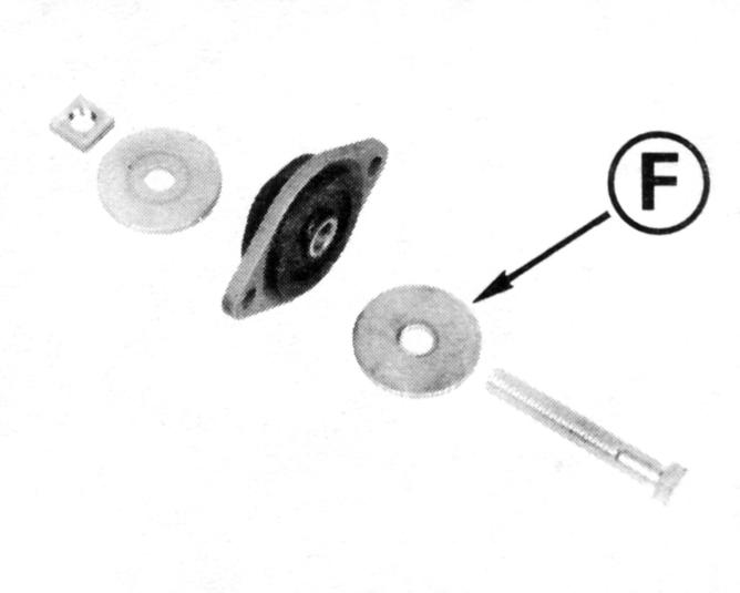
1.With engine off, disconnect high pressure (output) hose at pump. Use a spare pressure hose (D) to install Kent-Moore Tool, J-5176 (E) between pump and steering cyli nder pressure hose (F). Gauge must be positioned between shutoff valve and pump. Connect steering cylinder pressure hose to shutoff valve. Open shutoff valve.
2.Remove filler cap from pump reservoir and check fluid level. Fill pump reservoir to full mark on dipstick. Start engine, momentarily hold steering wheel against stop, and check connections at tool for leakage.
3.Bleed system as outlined under Purging Air From Steering System.
4.Insert Kent-Moore Thermometer Tool, J-5421 into reservoir filler opening. Start the engine and move steering wheel from stop-tostop several times until thermometer indicates that hydraulic fluid has reached its normal operating temperature of approximately 150° to 190° F (65° to 88° C).
5.Check fluid level; add fluid if required. When engine is at normal operating temperature, the pres sure reading on the gauge (valve open) should be in the 50-100 PSI (345-690 kPa) range. If pressure exceeds specifications, c heck the hoses for restrictions.
6.Pump relief valve pressure can be checked by momentarily closing the shutoff valve. Do not leave valve closed longer than it takes to read gauge; high hydraulic pressure s are developed. Relief valve pressure is approximately 10 00-1100 PSI (6895-7584 kPa).
Replace pump if fluid pressures or temperature do not meet specifications.
Cable Installation Problems
The hydraulic valve reacts to steering cable casing movement. Total valve movement is about 1/4 inch. This small motion is sufficient to operate the valve and direct hydraulic pressure to the appropriate side of the steering cylinder. Any restrict ion of movement of the steering cable casing at the stern of the boat will limit or restrict the movement of the valve and will result in hard steering in one or both directions.
When replacing the steering cable, the following points must be followed for proper power steering system operation:
1.Do not install a cable that is too short. Inadequate length will put tension on the cable casing, and cause binding of the steering cable. This will restrict valve movement, cause hard steering to port and a tendency to self steer to starboard.
2.Do not install a cable that is too long. Excessive length will push on the cable casing, and cause binding of the steering cable. This will restrict valve movement, caus e hard steering to starboard and a tendency to self steer to port.
3.Do not position steering cable in a sharp bend of less than 6 in. radius. Tight bends will cause binding and limit control valve movement. This will contribute to hard or uneven steering, or rough steering wheel movement.
4.Do not jam anything against cable at the engine end. Do not bind cable against inside of boat or against fuel tanks, battery boxes or flotation blocks. Jamming the stee ring cable will restrict steering cable movement and cause hard steering.
5.Do not interfere with or restrict steering cable movement through the last 90° of bend to the engine. Cable retainers, clips, clamps or tie straps should not be used in a manner that will restrict the cable movement near the engine. Do not attach wiring harness or control cables to this end of the steering cable.
NOTE!Do not restrict steering cable casing movement. Any restriction of the cable also restricts the valve movement. This will limit or stop hydraulic assist, or may hold the valve in one steering mode.
Feedback To The Helm
The steering system requires at leas t a little friction in the helm (and cable) to prevent hydr odynamic forces on the gear case from feeding back and turning the steering wheel without the operator activating the power assist system. This may happen on single engine installations (or on twin engines having both drives rotating in the same direction). Run the boat in a straight line in oppos ite directions at normal cruising speed with the drive trimmed in both a “bow up” position and in a “bow down” position. In each trim positi on, momentarily release the steering wheel to see if the wheel is turned by the gear case, and in which direction.
If the steering wheel turns to both starboard and port, then helm friction must be increased slightly. This will allow the power steering system to hold the desired steering position.
If the helm always turns in one direction (when it turns), it may be caused by a steering cable that is to o short, too long, or has restricted movement. See Cable Installation Problems. Twin engine problems may be corrected by adjusting the tie bar for “toe-in” or for “toe-out” of the sterndrives. Refer to Tie Bar Ad justment found in this section.