10 minute read
Section 3: Steering System


Special Tools
Kent-Moore Special Tools
Pump Pulley Remover 9995443-0
Pressure Gauge J-5176-E
Thermometer J-5421
Sealants, Lubricants and Adhesives Cleaning Solvent
Volvo Penta Grease
Volvo Penta Power Trim/Tilt & Steering Fluid
Volvo Penta Thread Sealing Agent
Loctite Primer
Safety Warnings
Before working on any part of the steering system, read the Safety section at the end of this manual.
When replacement parts are required, use genuine Volvo Penta or parts with equivalent characteristics including type, strength and material. Failure to do so may result in product malfunction and possible injury to the operator and/or passengers.
When working on an engine that is running or being cranked, use extreme care to avoid getting hands, fingers or clothing caught in the alternator, power steering supply pump and circulating pump belts, pulleys and other moving parts.
Power Steering System
Description
The power steering system consists of a mech anical cable from the helm to the inner transom plate, an engine mounted pump, an oil cooler, and a power cylinder to move the sterndrive steering arm.
The hydraulic pump is mounted on the front of the engine and is belt driven by the crankshaft pulley. The reservoir fill cap has a dipstick attached.
•The control valve and cylinder is a single unit mounted to the inner transom bracket.
•The oil cooler is a heat exchanger that uses engine cooling water to keep the hydraulic fluid cool.
•A high pressure hydraulic hose carries fluid from the pump to the control valve, and low pressure hoses and carry the fluid from the valve to the oil cooler, and back to the reservoir.
•The steering cable casing attaches to the steering cylinder valve.
•The cable ram passes through the valve and attaches to the clevis. The drive steering arm is also attached to the clevis.
Pump Operation
During normal operation, fluid is drawn into dual pump intake ports (1) from the reservoir (2). The reserv oir is supplied by a low pressure return line (3) from the power steering oil cooler. The pump output is through ports (4). The vanes (5) are held out against the pump bore by pressure behind the vanes. The pump has sufficient output (6) to allow quick boat maneuvers even at engine idle RPM. The pump output at high RPM is limited to about 2.3 gallons per minute by a flow restriction orifice (7).
The pump output pressure is determined by the resistance to flow of the system. When no steering changes are being made, the pressure will be about 50-100 PSI. When there is steering input, the pressure will be higher and will depend on the steering forces required due to the boat attitude, drive trim position, throttle position and quickness of the maneuver.
System Operation
No Steering Input - Steering Wheel Not Turning
The pump is protected from the ve ry high pressures by a pressure relief valve (8) that is located in the pump body. If the steering load becomes extremely high, the relief valve will open and limit the output pressure (9) to about 1,000-1,100 PSI.
Internal damage to the pump will occu r if the system is operated at relief valve pressure for more than a few seconds.
The pump has a metric output fitting. Use only a hose with a metric fitting.
When there is no steering input from the helm, the spring (1) keeps the spool valve (2) centered. Fluid from the pump enters the control valve through the pressure port (3), flows past both cylinder ports (4 and 5) with little restriction, then through the return port (6) and back to the reservoir in the power steering pump. There is a small amount of equal force at both ends (7) and (8) of t he cylinder and the cylinder does not move.
With no steering input, the sterndrive is held in one position and the boat moves in a constant turn or in a straight line.
Steering To Port - Steering Wheel Turning To Left
When the helm is turned to port (either turning boat to left or straightening from a right turn) the steerin g arm is pulled to starboard. The steering cable casing pushes the valve spool (2) to port. Fluid from the pump enters the valve at (3) and is routed to the rod-end outlet (4) and to the low volume side end of the cylinder (8). The pump pressure moves the piston and steering arm to starboard. Fluid in the high volume side of the cylinder (7) is forc ed out through the valve (5) from to return port (6) and back to the reservoir. As long as the helm is turning to port this motion continues, swinging the sterndrive to port.
When the helm input stops (steering wheel not turning), the steering cable stops pulling the steering arm to starboard, and the steering casing stops pushing the valve spool to port. When the spring (1) moves the valve spool to a “cent ered” position, hydraulic fluid is again routed past both cylinder outlets. The steeri ng cylinder has an equal force at
Steering To Starboard - Steering Wheel Turning To Right
both ends and stops moving. The steering system is then back to the No Steering Input condition described previously.
When the helm is turned to starboard (either turning boat to right or straightening from a left turn), the steering arm is pushed to port. The steering cable casing pulls the valve spool (2) to starboard. Fluid from the pump enters the valve at (3) and is routed to the piston-end outlet (5) and to the high volume side of the cylinder (7). The pump pressure moves the piston and steering arm to port. Fluid at the low volume side of the cylinder (8) is forced out and th rough the valve from (4) to return port (6) and back to the reservoir. As long as the helm is turning to starboard this motion continues, s winging the sterndrive to starboard. When the helm input stops (steering wheel not turning), the steering cable stops pushing the steering arm to port, and the steering casing stops pulling the valve spool to starboard. When the spring (1) moves the valve spool valve to a “centered” position, hydraulic fluid is again routed past both cylinder outlets. The steering cylinder has an equal force at both ends and stops moving. The steering system is then back at the No Steering Input condition described previously.
Steering Without Power Assist If the steering system is not providing power assist, the operator may still steer the boat. Turning the steer ing wheel to port causes the steering cable to pull the steering ar m to starboard. This causes the cable casing to push the valve spool valve (2) to port against the stop about 0.125 in. (3,18 mm). The steering cable then transmits the full manual effort to pull the steering arm.
The fluid (7) ahead of the piston is forced out of the cylinder through outlet (5) into the valve, and through return port (6) back to the reservoir. Additional fluid is drawn out of the reservoir through the pressure inlet (3) and (4) to the opposite side of the piston.
More steering effort is required sinc e all of the power required to steer the boat must be supplied by the operator, and additional force is required to move the fluid through the system when the pump is not operating.
Pump Removal
1.Place an oil drain pan under pump. Disconnect high pressure hose (1) and return hose (2) at pump. Do not lose O-ring on pressure hose fitting. Secure hose ends in a raised position to prevent fluid draining from hoses. Cap or tape ends of hoses to keep out dirt. Drain pump completely before removing.
NOTE!Some engine models may have the return line secured with a crimp style clamp. This type clamp is disposable and must be replaced with a worm screw type hose clamp during reassembly.
Serpentine Belt Models Only
1.On models with serpentine belt, release tension on the belt tensioner and remove the belt.
2.Remove pump pulley using special tool Volvo Penta P/N 9995443.
3.Remove three bolts securing pump to mounting bracket and remove pump.
V-Belt Models Only
4.Loosen pump bracket mounting screws and remove drive belt.
5.Remove pump mounting screws and remove pump from engine.
Pump Installation
6.Remove pump pulley using Pulley Remover, Volvo Penta P/N 9995443, then remove bracket from pump.
7.Remove mounting screws that se cure the bracket to the pump and remove bracket.
1.Attach mounting bracket to pump.
2.Attach pulley using Pulley Inst aller, Volvo Penta P/N 9995444-8.

3.Mount pump bracket loosely on the engine.
4.Make sure O-ring is in place and in good condition, then connect high pressure hose fitting. Tigh ten fitting to 15-26 ft. lb. (20-35 N•m).
5.Connect return hose to reservoir. Tighten hose clamp to 12-17 in. lb. (1,4-2,0 N•m).
Serpentine Belt Models Only
6.Fill pump reservoir with Volvo Penta Power Trim/Tilt & Steering Fluid. Bleed pump, hoses, and va lve by turning pulley clockwise (as viewed from front of engine) until reservoir no longer shows air bubbles. Keep reservoir filled while purging air from system.
Hydraulic Fluid
V-Belt Models Only
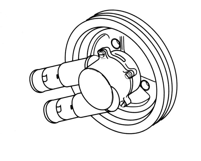
Release belt tensioner and install belt as shown.
1Crankshaft
2Belt tensioner
3Circulating water pump
4Alternator
5Idler Puller
6Power Steering Pump
Checking Fluid Level
7.Install drive belt and adjust belt tension See “Power Steering Pump Belt Adjustment” on page 103. Do not pry against pump reservoir while tightening belt.
8.Bleed entire system as outlined under Purging Air From Steering System.
NOTE!
Only use approved power steering fluid such as Volvo Penta Power Trim/Tilt & Steering Fluid. If this fluid is not available, use an automatic transmission fluid labeled Dexron or Dexron II.
1.Run engine and rotate steering wheel lock-to-lock for a reasonably long period of time to warm up steering fluid, then shut engine off. Remove reservoir filler cap and check if fluid level is at “HOT” mark on dipstick.
2.If fluid level is low, add recommended hydraulic fluid to bring fluid up to “HOT” mark on dipstick. Replace filler cap.
Caution!
Do not overfill a cold reservoir. Fluid could overflow when system reaches operating temperature.
Purging Air From Steering System
When system components have been serviced, pump must be refilled with fluid before engine is started. Perform the following steps to purge air from the steering system.
Caution!
Do not run pump even momentarily without fluid. Pump will be ruined or severely damaged.
1.With engine “OFF,” turn helm all the way to port. Add power steering fluid to bring fluid level to “COLD” mark on dipstick.
2.Start engine, run momentarily and shut off engine. Recheck fluid level and fill to “COLD” mark. Repea t this step as necessary until system no longer requires additional fluid.
3.Complete purging of air from system by starting engine and turning wheel slowly lock-to-lock. Maintain fluid level above pump body in reservoir.
4.Returning fluid with air in it will often be in the form of foam and will have a light tan or red appearance. Maintain fluid level high enough so foam is not drawn into pump inlet. All air must be eliminated from fluid before normal steering action can be obtained. If excessive foam accumulates in reservoir it must be removed, or let unit stand for an hour and repeat steps above.
5.After all air has been purged, retu rn wheel to centered position. Continue to run engine for several minutes and then shut engine off.
6.With engine “OFF” and with fluid at normal operating temperature, recheck to make sure fluid level is at “HOT” mark on dipstick.
7.Water test the boat to make su re the steering functions normally and is free from noise.
Power Steering Pump Belt Adjustment
Serpentine Belt Models
The belt tension is maintained by a belt tensioner. No adjustment is necessary.
V- Belt Models
Caution!
Improper power steering belt adjustment will cause a loss of power steering assist, resulting in hard steering. Check power steering belt tension midway between the circulating pump pulley and the power steering pump pulley.
To increase belt tension: Loosen pump mounting bracket screws, insert a 1/2 in. breaker bar into the square hole in the pump mounting bracket, and pivot pump away from engine as shown. While maintaining pressure on pump, retighten all mounting screws. Recheck belt tension. Never pry against the pump reservoir or pull filler neck.
The belts used for the power steering pump are heavy-duty. DO NOT replace with automotive belts.
Steering Cylinder
The steering cylinder assembly is a combination power cylinder and control valve. A piston rod clevis (1) provides the attachment to the steering arm and steering cable ram. The steering cable casing attaches to the threaded valve (2).
Cylinder Removal
1.Turn helm to port fu ll lock position. Remove the cotter pin (1) and the steering cable pin (2).
2.Hold steering tube with wrench. Loosen steering cable anchor nut and pull steering cable out of valve.
3.Remove cotter pin(1), then pull pin(2) out of clevis and steering arm.
4.Remove both hose fittings from the valve. Raise hoses and cover the ends to keep out dirt.
Caution!
Do not move cylinder rod in or out until cylinder has been drained completely. A dangerous spray of fluid can discharge from the cylinder ports if the rod is moved in or out.
5.Remove cotter pins (1) and loosen both anchor screws (2) until steering cylinder assembly can be removed.
Cylinder Servicing
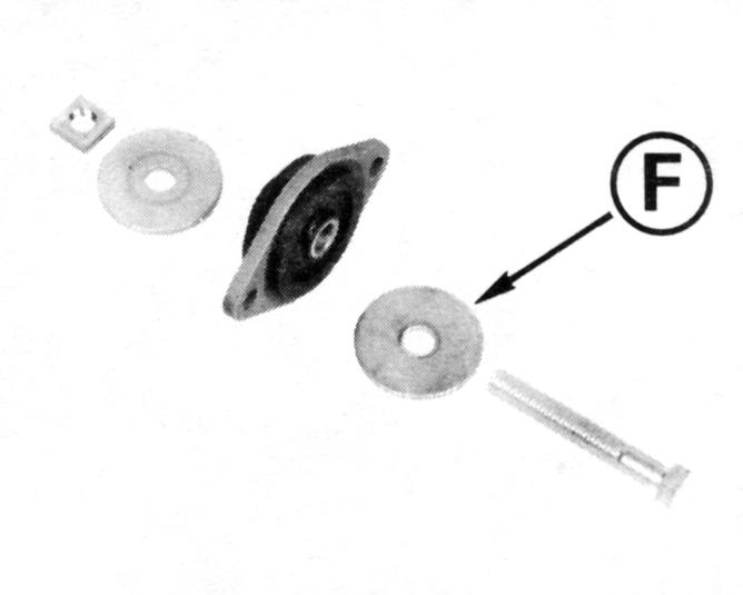
1.Pry out steering pivot bushings if they are to be replaced. If necessary they may be carefully drilled in two places with a 1/16 in. (1,5 mm) drill bit and then removed.
2.New bushings should be lubr icated and pushed into place.
Cylinder Installation
3.The cylinder rod should be wrapped with heavy paper or pasteboard and held in a vise with Rod Holder, Volvo Penta P/N 3854367-4. To remove unscrew the clevis (1).
4.To reinstall clevis, coat threads with Volvo Penta locking fluid P/N 1161053 and tighten to 23-28 ft. lb. (31-38 N•m).
1.Install anchor screws flush with inside of inner transom bracket.
2.Apply Volvo Penta Grease to both bushings.
Caution!
Filling the bushing pockets full with grease can cause the screws to hydraulically lock and break the transom plate when tightened.
3.Position steering cylinder assemb ly on inner transom bracket. Align bushings of steering cylinder with screws. Hand start both anchor screws to ensure alignment and engagement into bushings. Tighten anchor screws to 40-45 ft. lb. (54-61 N•m).
4.Install cotter pins through holes (1) in transom bracket from transom side. Spread ends of cotter pins to secure.
Caution!
Do not move cylinder rod if cylinder contains any fluid. A dangerous spray of fluid may discharge from the ports.
5.Connect hoses to cylinder. Star t each fitting by hand. Tighten pressure fitting to 10-12 ft. lb. (14-16 N•m). Tighten return fitting to 15-17 ft. lb. (20-23 N•m).
6.Pull steering arm (3) into hydrau lic cylinder clevis. Align holes and install large pin (2) from top of arm. Secure large pin by installing and spreading ends of cotter pin (3)