8 minute read
Section 6: Engine Removal and Installation

Special Tools
Safety Warnings
Before working on any part of the engine, read the Safety section at end of this manual.
Proper installation is important for the safe, reliable operation of all mechanical products. The procedures we recommend and describe in these instructions are effective methods to be followed when removing or installing the engine. Some of these methods require the use of tools specially designed for the purpose. The special tools should be used when and as recommended.
Alignment Tool 3851083-0
Universal Handle 3850609-3
Sealants, Lubricants and Adhesives
Volvo Penta Sealing Compound 1141570
Volvo Penta Grease 828250
3M Adhesive
Engine Removal
NOTE!Before removing engine, check engine height. See Determining Minimum Engine Height.
Check engine clearance between front of engine and engine compartment bulkhead prior to starting work. If clearance is less than 6 in. (15,2 cm), the sterndrive must be removed to disengage U-joint shaft from engine coupler. See Sterndrive and Transom Bracket Service Manual.
Warning!
To prevent possible fire and explosion caused by ignition of fuel vapors which may be present in the engine compartment, remove the positive and negative cables from the battery.
Disconnect BatteryCaution!
All switches must be in the “OFF” position prior to disconnecting the red (positive) and black (negative) cables from the battery. This will safeguard against permanent damage to electrical components.
Disconnect Power Steering Lines
1. Disconnect both power steering lines at the steering cylinder.
2. Cover both steering cylinder openings and line fittings to prevent fluid loss and entry of contaminants. Tie lines onto engine higher than power steering pump to prevent damage and loss of oil during engine removal.
23339 29830B
Disconnect Fuel Supply
Disconnect boat fuel line at the fuel filter inlet. Seal end of fuel line and inlet opening.
Disconnect Electrical Cables
1. Disconnect the plastic two-wire trim/tilt motor connector.
2. Remove wire retainer and unplug rubber two-wire trim/tilt sender connector. Cut tie strap securing sender cable, if required.
3. Unscrew worm clamp and disconnect large rubber instrument cable connector.
Disconnect Throttle Cable
4. Disconnect ground wires to the engine block grounding studs.
Disconnect Exhaust Hose
1. Remove cotter pin and flat washer (1) from throttle arm.
2. Loosen anchor retainer nut and rotate retainer away from cable trunnion. Remove throttle cable from throttle arm and anchor bracket.
1. Loosen four clamps on lower exhaust hose. For ease of moving lower hose, lubricate exhaust pipe.
2. To free lower hose from intermediate pipe, pry or twist hose. Slide hose down onto exhaust pipe.
Disconnect Water Hose
Loosen clamp and pull water supply hose off transom bracket water tube.
Separate Engine Mounts
1. Attach a hoist to lifting brackets of engine. Hoist must have a lifting capacity of at least 1500 lb. (680 kg).
2. Remove and retain both lock nuts (1) and both flat washers (2) from rear engine mounts.
3. Remove and retain lag screws from front engine mounts. If sterndrive was removed, lift engine out of engine compartment. If sterndrive was not removed, lift engine slightly and pull it forward to disengage U-joint shaft and flywheel coupler. With U-joint shaft clear of flywheel coupler, lift engine out of compartment.
Removal
1. Remove engine following previous procedure.
2. Remove and retain four exhaust pipe screws. Remove exhaust pipe and discard seal. Clean all material from transom bracket and exhaust pipe seal surfaces.
Exhaust pipe mounting holes have locking Heli-Coil® inserts. Do not clean screw holes with a thread tapping tool, otherwise locking feature will be destroyed and Heli-Coil will have to be replaced.
Installation
1. Coat a new seal with 3M Scotch Grip Rubber Adhesive 1300 and place in transom bracket groove.
2. Apply Volvo Penta Sealing Compound P/N 1141570 to the four exhaust pipe mounting screws.
3. Secure exhaust pipe to transom bracket with four screws. Tighten to 20-25 ft. lb. (27-34 N•m). Slide exhaust hoses and clamps onto exhaust pipes if they were removed.
4. Install engine.
Engine Installation
Attach Engine Mount
1. Lower engine into engine compartment:
•If sterndrive was not removed, and engine crankshaft was not rotated, engage U-joint shaft with engine coupler and slide engine back onto rear mounts. If coupler and U-joint shaft will not align, either the engine or U-joint shaft will have to be rotated to allow engagement. If engine mount height was disturbed, engine must be realigned as described later.
•If sterndrive has been removed, lower engine onto rear mounts.
2. Install flat washers into recesses of engine bracket and secure engine to mount with lock nuts. Tighten lock nuts to 28-30 ft. lb. (38-40 N•m).
Caution!
Do not use an impact wrench or power driving tool to install the lock nuts onto the studs.
3. Install forward engine mount lag screws and tighten them securely.
If sterndrive was not removed, go on to Exhaust Hose Attachment. If sterndrive was removed, continue with Engine Alignment section.
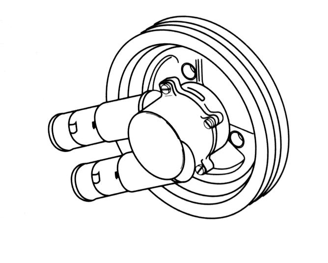
Engine AlignmentNOTE!Correct engine alignment is essential to long engine drive-train life. The front engine mounts may need adjustment UP or DOWN to produce correct engine alignment. Use Alignment Tool, Volvo Penta P/N 3851083-0, with Universal Handle, Volvo Penta P/N 3850609-31, to check engine alignment.
1. Slide alignment tool through driveshaft gimbal bearing. The alignment tool must slide through the gimbal bearing and into engine coupler with ease. If the alignment tool binds going into engine coupler, make sure the gimbal bearing is properly aligned. If gimbal bearing alignment is correct, the front engine mounts must be adjusted either UP or DOWN, as required, until alignment tool slides easily in and out of engine coupler.
2. To change engine height, tighten or loosen nuts (1) and (2) as required. See respective engine section, Front Mount Height Adjustment.
3. After correct alignment has been made, the front mount(s) must be tightened to maintain alignment.
•While holding one nut with an open-end wrench, tighten the second adjusting nut to 100-120 ft. lb. (136-163 N•m).
Push lower hoses up onto intermediate exhaust pipes.
Position and tighten all hose clamps securely between ribs of exhaust hose(s) as shown.
Caution!
DO NOT install hose clamps in expanded area of hose(s). Cooling will be restricted and engine damage will occur.
Connect Throttle Cable NOTE!Position
remote control handle in NEUTRAL, propeller should rotate freely. Turn propeller shaft and shift into the forward gear detent position, then pull handle HALFWAY BACK towards NEUTRAL. This positions the control for proper throttle adjustment. Failure to follow this procedure can result in “hard shifting” into gear.
1. Align internal bosses of trunnion with throttle cable groove. Press trunnion on throttle cable until seated.
Carbureted Models Only
2.4.3GL and Models: The engine thro ttle cable anchor block bracket has several sets of anchor block holes. The sets of holes marked with a “V” are used for Volvo Penta engines. The set of holes marked “43” are for 4.3 GL models. Holes marked GL are for all 5.0 and 5.7 Liter, carburetor models.
3. Install open end of trunnion in anchor block. Install screw in anchor block and position throttle cable assembly in selected set of holes. Nut must be against the anchor bracket, tighten it securely.
4. Throttle arm connector must have a minimum of 9 full turns or 1/4 in. (6 mm) of throttle cable thread engagement. Install throttle arm connector onto the throttle cable. Pull connector forward to remove all end play from throttle cable, then turn the connector in until hole aligns with the throttle arm stud.
NOTE!If throttle arm connector hole cannot be adjusted to align with the throttle arm, check for proper cable installation in the remote control box.
5. Install connector onto throttle arm. Install washer and cotter pin, and spread cotter pin prongs. Tighten jam nut against connector. For throttle and shift cable adjustment procedures, See “Installation of Shift and Throttle Cables” on page195.
Connect Water Hose
1. Slide hose clamp onto water inlet hose. Lightly lubricate inside of water inlet hose and push hose onto water inlet tube.
Connect Power Steering Lines
2. If inlet hose is not installed properly, underside of hose may collapse. Check underside of hose for proper installation and adjust hose as required. Tighten hose clamp securely.
NOTE!Failure to install water inlet hose correctly can result in powerhead damage from blockage of water circulation.
1. Remove tape or protective cover from small hydraulic hose fitting (or unscrew steering line connector) and small steering cylinder opening.
2. Install small hose fitting into steering cylinder.
3. Install large hose fitting into steering cylinder.
4. Tighten small hose fitting to 10-12 ft. lb. (14-16 N•m).
5. Tighten large hose fitting to 15-17 ft.lb. (20-23 N•m).
Connect Electrical Cables
6. Connect plastic two-wire plug of engine harness to two-wire receptacle of trim/tilt motor. Connectors should lock together. Route trim/tilt cable behind shift bracket.
7. Connect rubber two-wire trim/tilt sender plug to two-wire receptacle of instrument harness. Secure connectors with wire retainer and cable with a tie strap.
8. Connect ground wires from boat battery, and transom sheld to the engine grounding stud.
9. Route the instrument cable plug to join engine cable receptacle on engine.
Warning! Ensure cable is routed to prevent cutting or chafing on any sharp or hot object. This could result in an electrical short, and contribute to fire and explosion in the engine compartment.
10. Apply a light coat of Volvo Penta Grease grease around large engine plug.
11. Slide hose clamp over large engine receptacle. Align the two large terminals on plug and receptacle and press together. Slide hose clamp over receptacle and tighten securely.
12. All switches must be in the “OFF” position prior to connecting battery cables to the battery. Be sure polarity is observed; positive (+) cable to the positive terminal, and negative (-) cable to the negative terminal.
Warning!
Route all hoses and wires at least 1” (25 mm) away from the exhaust pipe or exhaust elbows. Under no circumstances should these items be allowed to come into contact with the exhaust pipe or exhaust elbows.
Connect Fuel Supply
Rear Engine Mounts
Removal
13. Attach boat’s fuel supply hose to fuel filter canister. On EFI models connect to the Fuel Cell. Tighten connection securely. Check for fuel leaks when testing engine, and repair any leaks that might occur.
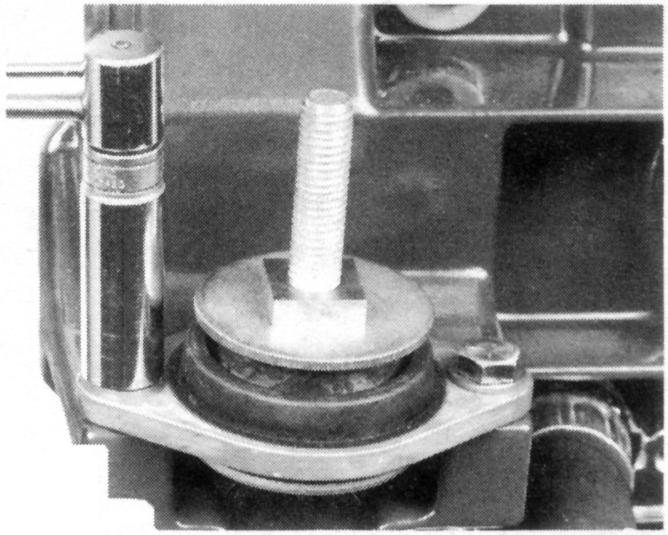
Disassembly
2. Unscrew two screws and washers, then lift mount assembly off transom plate.
Assembly
1. Hold square nut and remove screw. Mount assembly will break down into components shown. Pay particular attention to the two mount washers; their thickness, shape (concave or flat), and position in the assembly (above or below the rubber mount).
1. Slide lower washer onto mount bolt; make sure you choose the correct washer (as determined during the mount disassembly) for this position. Insert bolt into bottom (flat) side of rubber mount assembly, and install remaining washer and square nut. Do not tighten nut at this time.


NOTE!If top and bottom washers are not installed in their original positions, mount may transmit excessive engine vibrations into boat and cause undesirable operating conditions.
2. Turn mount assembly upside down and clamp square nut in vise. Rotate rubber mount until mounting holes are positioned at 90° to any side of square nut. Hold mount in this position and tighten center bolt to 44-52 ft. lb. (60-71 N•m).
NOTE!If 90° relationship between nut and mounting holes is not maintained, slot of engine mount pad cannot engage rear mount during installation.
1. Place mount assembly on transom plate. Install two screws and washers, and tighten them to 20-25 ft. lb. (27-34 N•m).
2. Install engine See “Engine Installation” on page145. Make sure mount pad slot engages square nut. Install both flat washers and locknuts, then tighten locknuts to 28-30 ft. lb. (38-41 N•m).