13 minute read
Section 5: Cooling System


Description
Raw Water Cooled Engines
Cooling water for the engine is picked up at the water intakes on both sides of the sterndrive lower gearcase. Water is pulled upward through the lower gearcase until it enters a wa ter tube that transfers it to the upper gear housing.
Water is pulled through the upper gear housing water passage where it meets a nipple and hose attached to the pivot housing. Water is routed through the transom mount as sembly to a tube that’s mounted on the inside of the gimbal housing. From this tube the water is drawn through a supply hose that ’s connected to the intake nipple of the supply pump.
Water is supplied to the engine by means of an impeller type pump (raw water supply pump). The raw water supply pump is mounted on the engine crankshaft. Water supplied to the engine is circulated in the engine by means of a centrif ugal type pump (circulating pump).
The shape of the housing and/or liner cause an eccentric action of the impeller blades during engine operation. During periods of high speed operation, the resistance of the water on its way through the pump is sufficient to prevent the ends of the impeller blades from making con- tact and following the inside perimeter of the pump housing. The blades merely flex in toward the ce nter of the impeller to perform as a combination centrifugal and positive displacement pump.
During low speed operation the im peller functions as a positive displacement pump. At higher speeds it functions as a combination centrifugal and positive displacement pump. Water exits the outlet nipple of the supply pump under pressure and carried through a hose to the inlet nipple of the thermostat housing.
The circulating pump is mounted on the front of the cylinder block. It has a pulley bolted to the pump shaft hub at its forward end. This in turn is driven by means of a belt from the crankshaft pulley. The pump shaft and bearing assembly is pressed in the water pump housing. The bearing is permanently lubricated dur ing manufacture and sealed to prevent loss of lubricant and entry of dirt. The pump is sealed against coolant leakage by a non-adjustable seal assembly pressed into the pump housing.
The water is now carried downward through the thermostat housing where it enters the flexible hose which attaches to the inlet pipe of the circulating pump. This inlet pipe is a part of the circulating pump housing and feeds the coolant into a low pressure area located at the axis of the impeller. Vanes on the rotating impeller cause the coolant to be thrown outward and into the cylinder block.
The cooling water flows rearward through the water jacket which surrounds each cylinder and ex tends below the lower limit of piston ring travel. After flowing the full length of the cylinder block, the water is forced upward through two passages and into the cylinder head. The water now flows forward in the cylinder head to cool the combustion chamber areas.
At the forward end of the cylinder head(s), the water enters the thermostat housing. If the water within the block is sufficiently warmed up, the thermostat will be open and a portion of the water will be pumped upward past the thermostat. The remainder will be returned via the flexible hose to the water pump for recirculation within the engine. The water which was pumped upward past the thermostat will enter the hose connected to the thermostat h ousing outlet and travel to the exhaust manifold.
At this point the water flows rearward through the manifold passages and into the high-rise elbow. All of the water that ente rs the high-rise elbow is mixed with the exhaust gas es prior to entering the exhaust pipe(s) and hose(s). This mixtur e of exhaust gases and water then enters the exhaust passages of the gimbal housing, pivot housing and sterndrive where it is discharged under water.
When the engine cooling water is cold, as in first starting up, the thermostat will be closed and will not allow any of the water to pass through for eventual discharge overboard. Instead, the water will be carried via the flexible hose back to the circulating pump for recirculation within the block. While the water within the block is recirculating, the supply pump is pumping water to the block.
Since this water is not able to enter the cylinder block, it is necessary to provide a method of discharge. Th is is provided by the bypass passage within the thermostat housing. If this were not provided, the resulting water pressure would be enough to force the thermostat off its seat, resulting in a greatly increased warm-up period.
Cooling System Troubleshooting
Quiz Customer for the Following Information: a.How old is unit, how many hours of operation? (Wear and corrosion.) b.How long has problem existed? (Gradual or sudden.) c.What were the operating conditions prior to problem? (Fresh or salt water, silt or sandy water.) d.What previous repairs and service have been made on unit? (Tune-ups, impeller replacement, etc.) e.At what RPM does problem occur? (Low, high.)
Possibilities To Consider: a.Temperature Gauge Malfunction.
•Improper or defective sender unit b.Engine Water Circulation Pump Malfunction.
•Malfunctioning gauge - Check ground wire - substitute good gauge.
•Loose alternator belt c.Water Intake Screens Blocked. d.Ventilation - Marine growth on keel, hull deformities, etc. e.Ignition Timing
•Impeller vanes worn - replace pump.
•Impeller shaft seal failure - replace pump.
•Running with retarded timing (carbureted engines only)Check timing.
Isolating Cooling Problem:
Air or exhaust gas entering cooling water: a. Procedure - Replace water hose between thermostat housing and the supply pump with clear pl astic hose. Operate unit in test tank or boat in water at RPM at which overheat occurs. b. Results and Conclusions - No bubbles in hose, air/ exhaust is not entering cooling water. Bubbles in hose, air/exhaust is entering cooling water. c. Check for - Defective lower gearcase water tube guide and seals; damaged water tube grom met; leaking water passage cover gasket or adaptor-t o-gear housing gasket.
NOTE! If operating unit in test tank, run motor in neutral. Some test tanks may not have sufficient water volume to allow running engine in gear without creating turbulence. This can be picked up by the water intake and misconstrued as evidence of a cooling problem.
Insufficient water supply: a. Procedure - Disconnect water s upply hose from transom bracket at thermostat housing. Operate engine at specified idle RPM. Hold end of hose level with the top of the flame arrestor. b. Results and Conclusions - A 1 inch (2,5 cm) head of water discharge, water supply is good. If less than 1/2 inch (1.2 cm), look for source of water loss. c. Check for - Blocked intake screens; damaged impeller housing O-ring or impeller plate gaske t; broken or worn impeller; defective pivot housing water passage O-ring or water drain screw seal; loose pivot housing- to-gimbal housing water hose clamps.
Thermostat malfunction a. Procedure - Operate engine until indicated temperature exceeds 160°F (71° C). Touch hoses between thermostat and exhaust manifold. b. Results and Conclusions - Hoses cold, thermostat is stuck closed. Hoses warm or hot, thermostat is good. c. Check for - Thermostat stuck open or closed, defective thermostat O-ring, correct thermostat style for engine type, clear thermostat housing bypass passage.
Engine head gasket leakage
Cooling System Components
a. Procedure - Allow engine to cool. Replace water hose(s) between thermostat housing and exhaust manifolds) with clear plastic hose. Operate unit at RPM at which overheat occurs.
b. Results and Conclusions - No bubbles evident, head gaskets not leaking. Bubbles evident, head gaskets leaking.
c. Check for - Cylinder compression using appropriate tester, water in engine oil, water in cylinders, spark plugs wet with water.
Hoses, Clamps, and Drain Plugs No special tools required.
Inspection Procedure: Examine all external cooling system components for leaks, wear, deterioration, and damage. Check all connections for tightness. Inspect hoses for cracks, checking or deterioration.
Repair Procedure: Repair or replace as required.
Water supply hoses used for replac ement must conform to S.A.E. 20R3, class D-2.
Thermostat
A 160° F (71° C) thermostat is standard.
Inspection Procedure: Check for proper rating and style, corrosion, restricted movement, or broken spring.
Test Procedure - Immerse the thermostat and a thermometer in a container of water. Heat water. Thermostat should start to open between 157-163° F (70-73° C), and should open to 5/32 in. (3,96 mm) minimum (A) at 182° F (83° C).
Repair Procedure: None, replace unit.
Manifold and Elbow
No special tools required.
Inspection Procedure: Pressure check components for leaks. Disassemble and inspect for corrosion or accumulation of foreign material.
Repair Procedure: Rod out any accumulation of foreign matter built up in water passages. If evidence of porosity between water passages and exhaust chambers or exterior is found, replace component. Install new gaskets on reassembly.
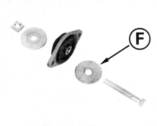
Circulating Pump - Engine
No special tools required.
Inspection Procedure: Make sure belt tension is correct. With the engine running, observe the rotation of the circulating pump pulley. If the pulley does not run true it can cause excessive drive belt wear and damage to the circulating pump itself.
If the leakage of water occurs at the circulating pump while the engine is in operation, the pump may be loosely mounted to the engine, the shaft seal in front of the pump ma y be bad, the backing plate gasket may be defective, or the circulatin g pump mounting gaskets are leaking.
If the above inspections do not detect any defect, the pump must be removed and inspected for internal corrosion, blockage, or damage. Inspect impeller for erosion.
Repair Procedure: None, replace the pump.
NOTE!Volvo Penta marine engines have a special circulating water pump with stainless steel components and a special marine shaft seal assembly. Do not replace with an automotive water pump.
Removal
1.Drain engine, refer to Draining Engine Block or Exhaust Manifold on page133.
2.Loosen bracket mounting screws and remove bracket.
3.Loosen hose clamps and remove hoses from supply pump. Note: The upper hose is the inlet hose.
1.Remove the four screws securing the housing.
2.Remove pump housing.
Cleaning and Inspection
3.Remove and discard O-ring.
Impeller Installation
4.Grasp impeller securely and pull from housing.
1.Clean all parts with solvent and blow dry thoroughly.
2.Clean sealing surfaces.
3.Inspect impeller housing for wear, cracks, gouges and distortion caused by freezing. If the sides of the impeller appear to be worn burned or charred, replace if necessary.
4.Inspect impeller; if blades are se t in a bent position, cracked or broken, or show flat instead of rounded edges on the housing contact surfaces, replace the impeller.
5.Check bearings for smooth operation.
1.Apply a light coat of glycerine to impeller surfaces. Install impeller until seated in the housing.
2.Apply a light coat of Volvo Penta Grease P/N 828250 to a new Oring. Install the O-ring onto the pulley and shaft assembly.
3.Install pump and secure with four screws. Tighten screws to 19-24 in. lb. (2,2-2,8 N•m).
4.Attach the inlet hose to upper nipple and the outlet hose to the lower nipple. Tighten hose clamps securely.
5.Orient pump assembly. Install bracket and secure with screws. Tighten screws to 20-25 ft. lb. (27-34 N•m).
Draining Engine Block or Exhaust Manifold
3.0GS-A, 3.0GL-A/B/C/D
1.With the engine turned off, locate and open the engine drain petcocks or remove drain plug as applicable (A) located on the port side of the engine block.
Caution!
Be sure that all water is dr ained from the engine. If no water drains when the petcocks are opened, remove the petcocks and use a piece of wire to clear any obstructions from the drain hole. Failure to drain all the water from the engine may result in engine damage during freezing temperatures.
2.Remove drain plugs from exhaust manifold (B). Raise or lower the bow of the boat to ensure complete drainage. After the water has completely drained, reinstall the drain plug and torque to 29 N•m (22 ft. lb.)
3.0GS-B/C
1.Locate the engine flush connector (A) at the front of the engine and is connected to a nipple on the port side of the engine block. Connect a garden hose to the connector with the supplied adapter.
NOTE! The hose connection adapter supplied with the engine may not work in all geographic locations.
Caution!
Do not run the engine during the flushing procedure. Water is not supplied to the raw water pump and the pump impeller will be damaged.
2.Turn the fresh water supply on and flush the engine with fresh water for 5 minutes to ensure the drain ports are open.
3.Turn off the fresh water supply and disconnect the garden hose from the engine flush connector. Lower the engine flush hose below the engine level and let drain.
4.After all of the water has drained out, reattach the hose cap and place back in original location.
5.Remove drain plug (B) from the exhaust manifold and let drain completely. Reinstall the drain plug and torque to 29 N•m (22 ft. lb.)
Caution!
If a garden hose with fresh water supply is unavailable, you must remove the hose nipple(s) from the engine to drain the engine block. To ensure all water is drained, clear the drain hole with a piece of wire. After the engine is drained reinstall the hose nipples and flush adapter as
Draining Supply Pump
removed. The exhaust manifolds are drained as described previously.
1.Loosen and slide hose clamps back. Remove hoses from the pump and drain.
2.Crank the engine no more than 2 seconds (DO NOT START) to expel any water trapped in water pump. Reattach hoses.
Thermostat Replacement
1.Remove all water hoses from the thermostat housing.
2.Remove thermostat housing from engine.
3.The thermostat is held in place by an O-ring (A). Pry the O-ring out of its groove, then lift the thermostat out of the housing.
4.Discard the housing gasket and O-ring. Thoroughly clean the housing and cylinder head gasket surfaces.
5.Place the thermostat in the housing. The temperature sensing element must face you when install ed. Install a new O-ring to seal thermostat in housing. Make sure O-ring is completely seated in its groove.
6.Coat both sides of a new gasket with Volvo Penta Gasket Sealing Compound P/N 1161099 and place it on the manifold. Install two screws. Tighten the screws to 20-25 ft. lb. (27-34 N•m).
7.Connect the water supply hose to nipple and tighten hose clamp securely. Connect the three remaining water hoses and tighten hose clamps securely. Make sure lifting eye is positioned as shown.
Caution!
If the water supply hose is attached to the wrong nipple, the engine will overheat.
Engine Flushing
3.0GS-B/C
1.Locate the engine flush connector (A) at the front of the engine and is connected to a nipple on the port side of the engine block. Connect a garden hose to the connector with the supplied adapter.
NOTE! The hose connection adapter supplied with the engine may not work in all geographic locations. If you need an adapter other than the one supplied, contact your Volvo Penta dealer for the correct adapter for you location.
Caution!
Do not run the engine during the flushing procedure for this model engine. Water is not supplied to the raw water pump and the pump impeller will be damaged.
2.Turn the fresh water supply on and flush the engine with fresh water for 5 minutes to ensure the drain ports are open.
3.If freezing temperatures are expec ted, drain engine, See “Draining Engine Block or Exhaust Manifold” on page133.
3.0GL-A/B/C/D/E
1.If the engine is running, shut it down.
2.Remove the blue plastic cap (A) from the hose that is clamped to the starboard side of the engine. It is marked with the running engine flush symbol.
3.Connect a water hose from a fresh water source to the flush connector on the engine (A).
4.Turn water on full and start the engine.
Warning!
Be sure to keep people and objects clear of the propeller area during the flushing proce dure. Accidental entanglement with the propeller is likely should the sterndrive be shifted into gear while the engine is running. Do not leave engine unattended while running.
5.Let engine idle until engine temperature stabilizes at its normal operating range. This will allow the thermostat to open and ensure the fresh water circulates throughout the engine.
6.After engine is flushed, shut engine the down.
7.Disconnect water hose and reinstall the cap.
CAUTION!
When re-installing the blue cap on the fresh water flush hose, tighten it by hand, then tighten 1/4 turn using a wrench. If the cap is too loose, air may be sucked in, causing the engine to overheat, resulting in damage.
Drain the engine if freezing temperat ures are expected. For details on draining the engine, please See “Draining Engine Block or Exhaust Manifold” on page133.
Numbers refer to Cooling System Flow Diagrams on the following pages.
1. Intake Screen - Blocked with debris.
2. Water Tube Guide and Seal - Improperly sealed.
3. Water Tube - Plugged with debris.
4. Grommet - Deteriorated, improperly seated.
5. Upper Gear Housing - Debris blocking pa ssage, freeze damaged.
6. Pivot Housing Seal - Damaged, out of position, improperly sealed.
7. Nipple O-ring - Out of position, improperly sealed, damaged.
8. Nipple - Blocked by debris, freeze cracked, loose in housing.
9. Water Hose and Clamps - Clamps loose, hose collapsed or leaking.
10. Transom Mount Water Tube - Blocked by debris.
11. Supply Pump (Engine Mounted) - Failed seal, corroded or bad bearings, eroded impeller, leaki ng mounting gaskets or backing plate.
12. Thermostat Housing - Corroded, restricted, or leaking gasket.
13. Thermostat - Defective thermostat, or wrong type for engine; improperly seated or damaged O-ring.
14. Belts - Loose, or worn and slipping.
15. Circulating Pump (Engine) - Failed seal, corroded or bad bearings, eroded impeller, leaking mount ing gaskets or backing plate.
16. Cylinder Block Water Passages - Corrosion, slag, blocked passages, or leaking core plugs.
17. Cylinder Head - Corrosion, slag, blocked passages or leaking gaskets.
18. Exhaust Manifold, Elbows, Gaskets, and Hoses - Gaskets improperly installed; corrosion, sand, or slag in manifold and elbows; hoses collapsed, burned through, or leaking.
19. Exhaust Pipe and Seal - Improperly sealed or installed, leaking.
20. Bellows, Clamp, and Retainer - Loose clamp, detached or torn bellows.
21. Power Steering Cooler - Restricted, or cracked and leaking.
22. Intake Manifold - Cracked casting, or leaking gasket(s).
23. Engine Oil Cooler - Restricted, or cracked and leaking.
In addition, check:
• Ignition Timing
• Boat Hull - Condition of hull, marine growth, or under- hull equipment.
Note!Fittings protruding through hull may cause air bubble streams which can be picked up by the lower gearcase and mixed with incoming cooling water to cause an overheat condition.