6 minute read
Section 4: Throttle & Shift Control System


Installation of Shift and Throttle Cables
Shift cable should “PULL” for forward gear on right-hand rotation SX and DP-S propeller applications. Sh ift cable should “PUSH” for forward gear on left-hand rotation SX propeller applications. Throttle cable should “Push” to close for Vo lvo Penta remote controls. Failure to do so could result in loss of control of the boat and possible injury to the boat occupants.
1.If the remote control shift and throttle cables are installed in the remote controls, proceed to Check Remote Control Shift Cable Stroke.
2.If the remote control shift and throttle cables have not been installed, the following procedure will permit you to order the correct length remote control shift and throttle cables.
3.Measure the proposed route of t he remote control shift and throttle cables. All bends must have a radi us greater than 6 inches (15,2 cm).
•Remote control shift cable: Add (A)+(B) plus 20 in. (50.8 cm), round up to next cable length.
•Remote control throttle cable: Add (A)+(B)+(C) plus 4 in. (10.1 cm), (C is to center of thrott le arm pin). Round up to next cable length.
Caution!
When removing shift and throttle cables from the packing box, DO NOT bend the cables tighter than a 6 inch radius.
Check Remote Control Shift Cable Stroke
1.Move the remote control handle to the wide-open-throttle position in the direction needed to retract the shift cable. Pull out cable core wire to remove end play. Mark cable core wire at end of casing.
2.Return remote control shift handle to the neutral detent position. Measure and record the distance between the mark and end of casing.
3.Mark cable core wire at end of casing with control in the neutral detent position.
4.Move the remote control handle to the wide-open-throttle position in the direction needed to extend the shift cable. Push in on cable core wire to remove end play. Measure and record the distance between mark and end of casing.
•The distance between forward and neutral must be no less than 1¼ in. (31.8 mm) and no greater than 13/8 in. (35.0 mm).
•The distance between neutral and reverse must be no less than 1¼ in. (31.8 mm) and no greater than 13/8 in. (35.0 mm).
NOTE!Check your remote control installation instructions, if your measurements are not within these specifications. Make sure the cables are attached correctly inside the control box and move in the proper direction for your application before continuing. Refer to the remote control installation instructions for this information. All control boxes must meet these minimum and maximum specifications in order for the shift system to function properly.
NOTE!If the throttle cable is attached to the throttle arm and anchor block, remove it from both. The throttle cable must be disconnected from the throttle arm prior to shift cable installation and adjustment to prevent “loading” the control box and adversely affecting shift adjustments.
Shift Cable to Sterndrive
Before beginning, shift remote control handle into NEUTRAL detent position; the propellers should rotate freely.
NOTE!Remote control shift and thro ttle cables must be SAE type cables.
1.Note position of small seal and large seal on the shift cable, Remove and retain jam nut, small seal, and large seal from the shift cable.
2.Apply a light coat of Volvo Penta Grease to the end of the remote control shift cable casing. Slide sh ift cable through shift cable tube until it appears on the outside of the transom.
3.For ease of installation of shift cable, turn sterndrive to port. Reinstall the retained large seal and small seal onto the shift cable in the same position as noted in step 1.
5.Slide shift cable through pivot housing and sterndrive. Slide clamp in fully, engaging the shift c able anchor groove. Tighten clamp screw to 61- 97 in. lb. (7-11 N•m). Check that cable clamp is fully engauged into the shift cable slot after torquing the screw.
Throttle Cable to Engine
9.Rotate shift lever back to neutral detent position, then move remote control handle to its neutral detent position. Turn anchor pin IN or OUT until it aligns with center of bell crank slot.
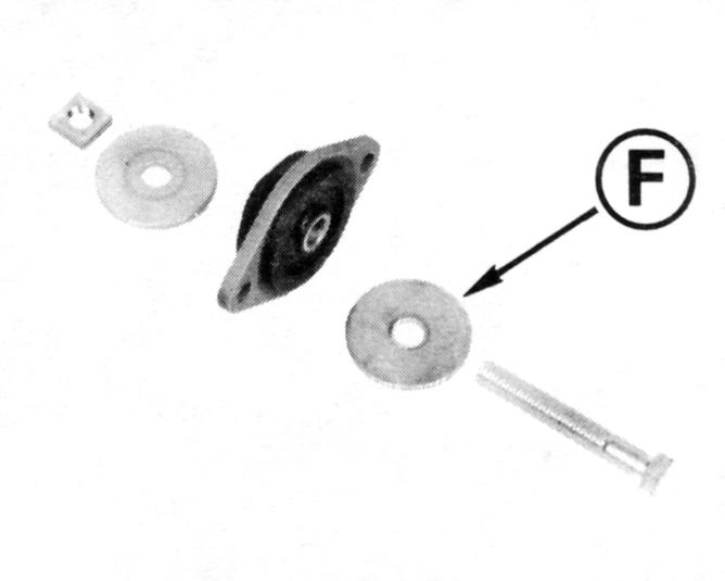
10.Install anchor pin, flat washer, and cotter pin. Spread prongs of cotter to secure anchor pin. Install jam nut and tighten securely against anchor pin.
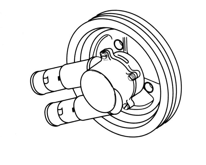
11.Reinstall rear cover and secure with three original screws. Tighten screws to 108-132 in. lb. (12-15 N•m).
Determine whether you have a “pus h-to-close” or “pull-to-close” remote control system. Cable attachment point at throttle arm is determined by direction of control cable movement. Incorrect attachment may cause hazardous boat operation.
NOTE!The remote control shift cable must be installed prior to throttle cable installation. This will ensure proper throttle and shift system operation when using single lever controls.
1.Position control handle in NEUTRAL and propeller should rotate freely. Turn propeller shaft and shift into the FORWARD gear detent position, then pull handle HALFWAY BACK towards NEUTRAL . This positions the control for proper throttle adjustment. Failure to follow this procedure can result in “hard shifting” out of NEUTRAL
2.Make sure throttle lever is against idle stop screw.
3.Align internal bosses of trunnion with throttle cable groove. Press trunnion on throttle cable until seated.
4.The engine throttle cable anchor block bracket is part of the engine lifting bracket and is located port and aft on the exhaustmanifold.
5.Install open end of trunnion in anchor block. Install screw in anchor block and position throttle cable assembly in selected set of holes. Locknut must be agains t the anchor bracket, tighten it securely.
6.Throttle arm connector must have a minimum of 9 full turns or 1/4 in. (6,4 mm) of throttle cable thread engagement. Install throttle arm connector onto the throttle cabl e. Pull connector forward to remove all end play from throttle cable, then turn the connector in until hole aligns with the “push-to-c lose” or “pull-to-close” throttle arm stud.
NOTE!If throttle arm connector hole cannot be adjusted to align with the throttle arm, check for proper cable installation in the remote control box.
7.Install connector onto appropriate throttle arm stud. Install washer and cotter pin, and secure by spreading end of cotter pin. Tighten locknut against connector.
Neutral Start Switch Tests
Electrical
1.All switches must be in the “OFF” position, then disconnect battery cables at the battery before servici ng electrical systems. Failure to do so could result in injury from:
•shorted battery positive (B+), causing a burn or an electrical fire.
•contact with moving parts, if the engine is accidentally cranked or started.
2.Move the control handle to the NEUTRAL position. Disconnect the yellow/red lead from the key switch and the yellow/red lead from the instrument wiring harness.
3.To test the continuity, calibrate an ohmmeter on high ohms scale. Connect the ohmmeter to the two leads. The meter should read zero (0).
4.Move the remote control handle to the FORWARD gear position. The meter should read infinity (). Move the remote control handle to the REVERSE gear position. The meter should read infinity ().
Mechanical
5.5. If the meter does not show (), check the ohmmeter connections and test again. Replace the neutral start switch if the meter still fails to show () when the remote control handle is in the FORWARD and REVERSE gear position. Refer to the procedures in Disassembly of Remote Contro l to replace the neutral safety switch.
1.With the boat in water and the remote control in NEUTRAL, turn the ignition key to the start position. The engine should start.
2.Disengage the remote control handle and move it into the FORWARD warm-up position. The engine should start.
3.Disengage the remote control handle and move it into the REVERSE warm-up position. Again the engine should start. Move the remote control handle back into NEUTRAL.
4.Move the remote control handle to the FORWARD gear position. The engine should NOT start. Move the handle to the REVERSE gear position. Again the engine should NOT start.
5.If the engine starts when the remote control handle is in either the FORWARD or REVERSE gear positi on, replace the neutral start switch. Refer to the procedures in Disassembly of Remote Control to replace the neutral safety switch.
Removal of SAE Remote Control Cables
NOTE!Should it become necessary to remove or replace the remote control cables, the attachment at the engine and sterndrive is very important. Follow these steps for removal of remote control cables.
Before beginning, shift remote control handle into NEUTRAL detent position; the propeller should rotate freely.
Throttle Cable From Engine
1.Remove cotter pin and flat washer from throttle arm.
2.Loosen anchor retainer nut and rotate retainer away from cable trunnion. Remove throttle cable from throttle arm and anchor bracket.
Shift Cable From Sterndrive
1.Remove drive’s rear cover. Remove cotter pin (1) and flat washer from anchor pin (3). Remove jam nut (2) from shift cable core wire.
2.Remove anchor pin from bell crank slot. Unscrew anchor pin from shift cable core wire.
3.Loosen screw and slide retainer ou t of shift cable anchor groove. Pull the shift cable from drive and transom bracket cable tube.