44 minute read
Valve Lash Adjustment


Warning!
If adjusting the valves while the engine is installed in the boat, be sure the ignition system is disabled by disconnecting the purple and grey wire connector on the ignition coil before attempting to rotate the engine with the valve cover removed.
3. Adjust the rocker arm nuts as follows: a. Turn the crankshaft until the mark on the crankshaft pulley lines up with “0” on the timing tab and number 1 cylinder is at top dead center. b. Place fingers on the number 1 valves as the mark approaches “0.” If the valves move as the mark approaches “0,” the engine is on number 4 top dead center and should be rotated one more revolution in order to reach number 1 top dead center. c. With the engine at number 1 top dead center, adjust the following valves:
–The exhaust valves 1,3
–The intake valves 1,2,4
4. Adjust the correct valves as follows: a. Back off the rocker arm nut until the lash is felt in the valve pushrod. b. Tighten the rocker arm nut until all the lash is removed. c. Zero lash can be felt by moving the pushrod up and down between your thumb and forefinger until there is no more movement. d. When all the free play is gone, tighten the valve rocker arm nut 1 additional turn (360 degrees). e. Turn the crankshaft 1 revolution until the mark on the crankshaft pulley lines up with “0” on the timing tab. This is number 4 top dead center. f. With the engine at number 4 top dead center, adjust the following valves:
–The exhaust valves 2,4
–The intake valves 3 g. Back off the rocker arm nut until the lash is felt in the valve pushrod. h. Tighten the valve rocker arm nut until all the lash is removed. i. Zero lash can be felt by moving the valve pushrod up and down between your thumb and forefinger until there is no more movement. j. When all the free play is gone, tighten the valve rocker arm nut 1 additional turn (360 degrees).
Hydraulic Valve Lifter
Removal
1. With air hose and cloths, clean dirt from cylinder head and adjacent parts to avoid getting dirt into engine. It is extremely important that no dirt gets into the valve lifters.
2. Disconnect ventilation hose, fuel line, and fuel pump overflow hose. Remove rocker arm cover See “Rocker Arm Cover” on page32
3. Loosen rocker arm nuts and pivot the rocker arms free of the push rods.
4. Disconnect spark plug wires at plugs. Remove high tension lead from coil. Remove both connectors from coil. Remove coil and mounting bracket from cylinder head See “Ignition Coil” on page31
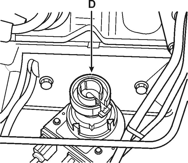
5. Remove both connectors at distributor. Take off cap, note distributor rotor (D) position and remove distributor See “Distributor” on page30
6. Remove push rod cover and gasket See “Pushrod Cover” on page33
7. Remove push rods and lift out valve lifters that require service. Place lifters in a wooden block having numbered holes, or use other suitable means of identifying them according to original position in the engine.
J3049-A
Tools Required
•J 3049 Valve Lifter Remover (Plier Type)
•J 9290-01 Valve Lifter Remover (Slide Hammer Type)
8. Use the J 3049 in order to remove the valve lifters.
J9290-01
9. If the valve lifters cannot be removed with the J 3049 use the J 9290-01 in order to remove the valve lifters.
Valve Train Components Inspect (Cylinder Head)
1. Inspect the following areas:
•The valve rocker arms and ball at the mating surfaces. These surfaces should be smooth and free of scoring or other damage.
•The valve pushrod sockets and valve stem mating surfaces. These surfaces should be smooth with no scoring or exceptional wear.
•The valve pushrods for bends or scored ends.
2. If less than a complete set of lifters is being removed, immediately disassemble and inspect one or two for presence of dirt or varnish. If lifters contain dirt or varnish, it is advisable to replace all lifters. Otherwise, it will be satisfactory to service only those lifters that are not operating properly.
3. Examine the cam contact surface at lower end of lifter body. If this surface is excessively worn, galled or otherwise damaged, discard the lifter assembly. In this case, also examine the mating camshaft lobe for excessive wear or damage.
ROTATING - NORMAL, OK - NOT ROTATING
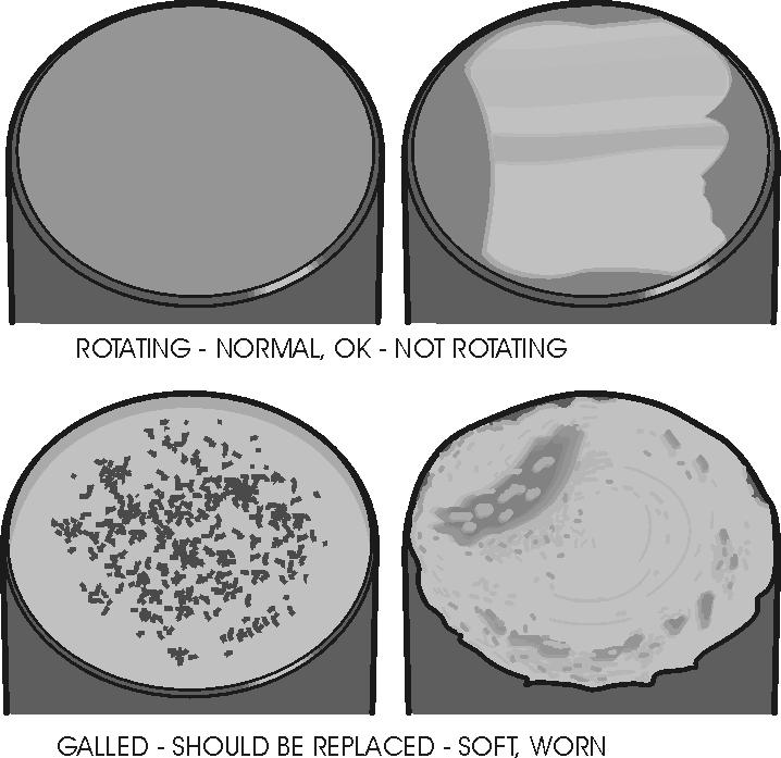
GALLED - SHOULD BE REPLACED - SOFT, WORN
InstallationNOTE!Before installing any new lifters, coat the bottom of each lifter with Molykote Lubricant or its equivalent.
1. Install valve lifters in cylinder block. If any new lifters or a new camshaft has been installed, an additive containing EP lubricant such as GM Engine Super Oil Supplement must be added to the crankcase oil for break-in.
2. Install push rods onto lifters and install push rod cover with a new gasket.
3. Install distributor (position rotor to mark on housing and block). Install coil and bracket. Connect both connectors to coil. Install distributor cap and attach spark plug and coil wires. Connect both connectors to distributor.
4. Install shift bracket assembly.
5. Pivot rocker arms in place and turn adjusting nuts the amount necessary to eliminate lash.
Valve Spring and Seal Repair
RemovalCaution! Wear safety glasses
1. Remove rocker arm cover, See “Rocker Arm Cover” on page32
2. Remove spark plug, rocker arm, and push rod on the cylinder(s) to be serviced.
3. Install Air Line Adapter tool J-23590 to spark plug port and apply compressed air to hold the valves in place.
J23590
4. Using valve spring compressor J 38606 to compress the valve spring, remove the valve locks, valve cap and valve spring and damper.
NOTE!Do not remove the spring from the compressor unless the spring needs testing or replacement.
5. Remove the valve stem oil seal.
Installation1. Install seal over valve stem and seat against head.
2. Set the valve spring and damper, valve shield and valve cap in place. Install oil seal in the lower groove of the stem, making sure the seal is flat and not twisted.
A light coat of oil on the seal will help prevent twisting.
3. Install the valve locks and release the compressor tool making sure the locks seat properly in the upper groove of the valve stem. Grease may be used to hold the locks in place while releasing the compressor tool.
4. Using Vacuum Pump J-23738-A, apply vacuum to the valve cap to make sure no air leaks past the seal.
5. Install spark plug and tighten to 20 ft. lb. (27 N•m).
6. Install and adjust valve mechanism See “Valve Lash Adjustment” on page34
Cylinder Head
The condition of the cylinder head and valve mechanism significantly determines the power, performance and economy of the valve-in-head engine. Extreme care should be exercised when conditioning the cylinder head and valves. Maintain correct valve stem to guide clearance, correctly grind valves and valve seats, and properly adjust valves.
Removal1. Remove intake and exhaust manifold See “Intake/Exhaust Manifold” on page28
2. Disconnect coolant hoses at thermostat housing. Disconnect spark plug wires and remove spark plugs.
3. Disconnect fuel line retaining clips at thermostat housing and cylinder head. Disconnect wire harness from the temperature sending unit, leaving harness clear of clips on rocker arm cover. Remove thermostat housing assembly from front of cylinder head. Disconnect fuel line at the fuel pump and remove.
4. Remove the rocker arm cover. Next, back off the rocker arm nuts and pivot the rocker arms to clear the push rods. Remove the push rods.
5. Remove the ignition coil and bracket.
6. Remove the cylinder head bolts, cylinder head, and gasket. Place the cylinder head on two blocks of wood to prevent damage to the head.
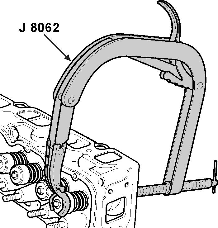
Disassembly1. Remove rocker arms nuts, ball seats and rocker arms. Use tool J-8062, compress the valve springs and remove valve stem keys. Release the spring compressor tool and remove exhaust valve rotator or intake valve cap, shield, spring and seals.
2. Remove valves from bottom of cylinder head and place them in a rack in their proper sequence so they can be assembled in their original positions.
Cleaning1. Clean all carbon from combustion chambers and valve ports using tool J-8089. Inspect the cylinder head for cracks in the exhaust ports, combustion chambers, or external cracks to the water chamber. Clean carbon deposits from head gasket mating surfaces.

2. Thoroughly clean the valve guides. Clean all carbon and sludge from push rods and rocker arms.
3. Clean valve stems and heads on a buffing wheel. Inspect the valve for burned head, worn seat, cracked faces, or damaged stems.

4. Wash all parts in cleaning solvent and dry them thoroughly. Check fit of valve stems in their respective bores.
5. Measure valve stem clearance as follows: Clamp a dial indicator on one side of the cylinder head rocker arm cover gasket rail, locating the indicator so that movement of the valve stem from side to side (crosswise to the head) will cause a direct movement of the indicator stem. The indicator stem must contact the side of the valve stem just above the valve guide. With the valve head dropped about 1/16 in. off the valve seat; move the stem of the valve from side to side using light pressure to obtain a clearance reading. If clearance exceeds specifications it will be necessary to ream valve guides for oversize valves as outlined.
NOTE!Excessive valve stem to bore clearance will cause lack of power, oil consumption, rough idling and noisy valves, and may cause valve breakage. Insufficient clearance will result in noisy and sticky functioning of the valves and disturb engine smoothness of operation. Intake valve stem to bore clearance should be 0.001-0.0027 in. (0,0250,007 mm). Exhaust valve stem to bore clearance should be 0.0007-0.0027 (0,01778-0,06858 mm). By using a micrometer and a suitable hole gauge, check the diameter of the valve stem in three places; top, center and bottom. Insert hole gauge in valve guide bore, measuring at the center. Subtract highest reading of valve stem diameter from valve guide bore center diameter to obtain valve to valve guide clearance. If clearance is not within limits use next oversize valve and ream bore to fit using suitable reamer.
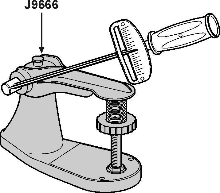
6. Check valve spring tension with tool J-9666 spring tester.
NOTE!On all models, springs should be compressed to 1.61 in. (40,89 mm) at which height it should check 100-110 pounds (444-490 N). Weak springs affect power and economy and should be replaced.
7. Check valve lifters for free fit in block. The end that contacts the camshaft should be smooth. If this surface is worn or rough, the lifter should be replaced. If lifter is damaged, check the corresponding camshaft lobe for damage.
Repair
Valve Guide Bore Valves with oversize stems are available for inlet and exhaust valves in the following sizes: 0.0003 in., 0.015 in., and 0.030 in. Use the 11/32 in. diameter reamer sizes from reamer tool set J-5830-02 which are: J-4822 standard; J-5830-1, 0.003 in oversize, J-5830-2, 0.015 in. oversize and J-5830-3, 0.030 in. oversize to ream the bores for the new valves.

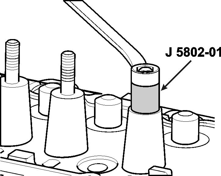
Rocker Arm Studs Rocker arm studs that have damaged threads may be replaced with standard studs. If the studs are loose in the head, oversize studs (available in 0.003 in. or 0.013 in. oversize) may be installed after reaming the holes as follows: NOTE!Do not attempt to install oversize stud without reaming stud hole.
a. Remove old stud by placing tool J-5802-01 over the stud. Install nut and flat washer, and remove stud by turning nut.
Valve Seats Reconditioning the valve seats is very important, because seating of the valve must be perfect for the engine to deliver the power and performance built into it.
Another important factor is the cooling of the valve heads. Good contact between each valve and its seat in the head is imperative to ensure that the heat in the valve head will be properly carried away. Several different types of equipment are available for reseating valve seats; the recommendations of the manufacturer of the equipment being used should be carefully followed to attain proper results. Regardless of what type of equipment is used, however, it is essential that valve guides be free from carbon or dirt to ensure proper centering of pilot in the guide.
a. Install expanding pilot in the valve guide bore and expand pilot by tightening nut on top of pilot.
b. Place roughing stone or forming stone over pilot and just clean up the valve seat. Use a 46° stone for both the inlet and exhaust valve seats.


c. Remove roughing stone or forming stone from pilot, install finishing stone on pilot and cut just enough metal from the seat to provide a smooth finish.
d. Narrow down the valve seats to the proper width for the intake and exhaust. See Engine Specifications.
NOTE!This operation is done by grinding the port side with a 30° stone to lower seat and a 60° stone to raise seat.
e. Remove expanding pilot and clean cylinder head carefully to remove all chips and grindings from above operations.
NOTE!Valve seats should be concentric to within 0.002 in. total indicator reading.
Valves Valves that are pitted can be refaced to the proper angle, ensuring correct relation between the head and stem on a valve refacing machine. Valve stems which show excessive wear, or valves that are warped excessively should be replaced. When a valve head which is warped excessively is refaced, a knife edge will be ground on part or all of the valve head due to the amount of metal that must be removed to completely reface. Knife edges lead to breakage, burning or pre-ignition due to heat localizing on this knife edge. If the edge of the valve head is less than 1/32 in. thick after grinding, replace the valve.
a. If necessary, dress the valve refacing machine grinding wheel to make sure it is smooth and true. Set chuck at 45° mark for grinding valves.
b. Clamp the valve stem in the chuck of the machine.
c. Start the grinder and move the valve head out in line with the grinder wheel by moving the lever to the left.
VE099-3L d. Turn the feed screw until the valve head just contacts wheel. Move valve back and forth across the wheel and regulate the feed screw to provide light valve contact. e. Continue grinding until the valve face is true and smooth all around valve. If this makes the valve thin the valve must be replaced as the valve will overheat and burn. f. Remove valve from chuck and place stem in “V” block. Feed valve squarely against grinding wheel to grind any pit from rocker arm end of stem. g. After cleaning valve face and cylinder head valve seat of grinding particles, make pencil marks about 1/4 in. apart across the valve face, place the valve in cylinder head and give the valve one-half turn in each direction while exerting firm pressure on face of valve. h. Remove valve and check face carefully. If all pencil marks have not been removed at the point of contact with the valve seat, it will be necessary to repeat the refacing operation and again recheck for proper seating. i. Grind and check remaining valves in the same manner.
NOTE!Only the extreme end of the valve stem is hardened to resist wear. Do not grind end of stem excessively.
Assembly1. Starting with number one cylinder, place the exhaust valve in the port, and place the valve spring (A) and cap (B) in position. Place spring and cap on exhaust valves. Then, using tool J-8062, compress the spring and install the oil seal (C) and valve keys (D). See that the seal is flat and not twisted in the valve stem groove and that the keys seat properly in the valve stem groove. Place valve springs in position with the closed coil end toward the cylinder head.

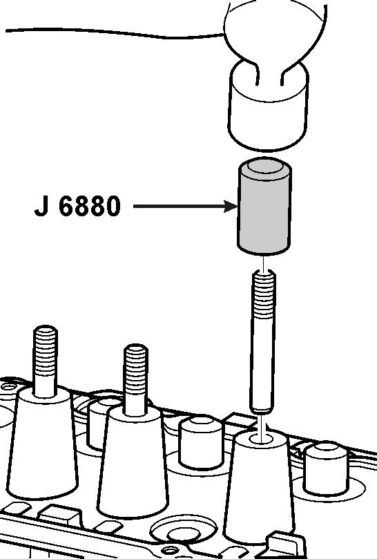
2. Assemble the remaining valve, valve springs, spring caps, oil seals and valve keys in the cylinder head using tool J-8062. Check seals by placing a vacuum cup over valve stem and cap, squeeze vacuum cup to make sure no oil leaks past oil seal.
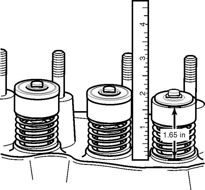
3. Check the installed height of the valve springs using a narrow, thin scale to measure from the top of the shim or spring seat in the head, to the top of the valve spring cap. If this is found in excess of 1.65 in. (41,91 mm), install a valve spring seat shim, approximately 1/16 in. (1,858 mm) thick. At no time should the spring be shimmed to give an installed height of less than 1.65 in. (41,91 mm).
NOTE!If springs are to be changed with cylinder head installed, See “Valve Spring and Seal Repair” on page37
Installation1. The gasket surfaces of both the head and the block must be clean and free of any foreign matter, and free of nicks or heavy scratches.
2. Cylinder head bolt threads in the block must be cleaned as well as the threads on the cylinder head bolts. Dirt will affect bolt torque.
3. Place a new cylinder head gasket in position over the dowel pins in the cylinder block. On engines with a steel gasket coat both sides of a new gasket with a thin, even coat of Volvo Penta Gasket Sealing Compound. Too much sealer will hold the beads of the gasket away from the block or head.


NOTE!The 3.0 Liter engine has a special marine head gasket. Do not substitute an automotive head gasket.
4. Carefully guide cylinder head into place over dowel pins and gasket. Coat threads of cylinder head bolts with Permatex No. 2. Install the bolts and run them down to the block.
5. Tighten the cylinder head bolts, with a torque wrench, in three progressive steps following the sequence shown.
Step 1 - 35 ft. lb. (47 N•m)
Step 2 - 65 ft. lb. (88 N•m)
Step 3 - 90 ft. lb. (122 N•m)

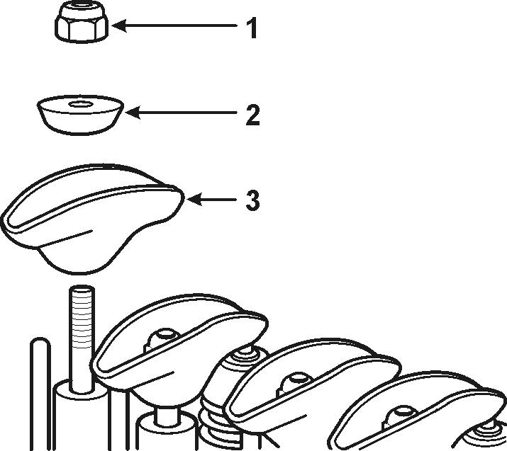
6. Install valve push rods down through openings in the cylinder head and seat them in lifter sockets.
7. Install rocker arms (3), balls (2), and nuts (1). Tighten rocker arm nuts until all push rod play is taken up.
8. Install thermostat housing using a new gasket. Attach coolant hoses.
9. Clean all spark plugs with abrasive-type cleaner, inspect for damage (replace if necessary) and set the gap at 0.045 in. (1.14 mm) using a wire gauge. Install the spark plugs. Tighten spark plugs to 20 ft. lb. (27 N•m).
10. Install coil and connect both connectors to coil. Connect wire to temperature sending unit.
11. Clean manifold gasket surfaces and install new gasket over manifold studs. Position manifold and slide it into place over the studs, making sure it seats against the gasket. Install bolts and nuts and tighten as described under heading Intake/Exhaust Manifold.
12. Adjust valve lash See “Valve Lash Adjustment” on page34 Install rocker arm cover and gasket. Tighten screws to 40 in. lb. (5 N•m).
13. Connect throttle linkage and adjust See “Installation of Shift and Throttle Cables” on page117
Timing Gear Cover
14. Connect fuel line and overflow hose to carburetor and install fuel line support clamps (two). Clean and install flame arrestor.
15. Start engine and check for fuel, coolant, and exhaust leaks.
Removal1. Drain coolant from block and exhaust manifold.
2. Securely support engine and remove front engine mount.
3. Remove alternator and power steering belts. Next remove harmonic balancer and pulley assembly from pulley hub.
4. Install puller tool J-6978-E to pulley hub with three 3/8-24 x 2 in. bolts and remove hub. Remove puller tool.

5. Remove circulating pump pulley.
6. Remove crankcase oil drain tube cap and withdraw oil with a suction pump.
7. Disconnect oil drain tube and remove.
8. Remove timing gear cover attaching screws. Remove cover and gasket.
Oil Seal Replacement
Engine Front Cover Removal1. Remove oil pan See “Oil Pan Replacement” on page75
1. Remove the engine front cover bolts.
2. Remove the engine front cover.
3. Remove the gasket.
4. Discard the gasket.
5. Remove the oil seal from the front cover.
6. Clean the engine front cover in solvent.
7. Inspect the engine front cover for damage to the gasket surface or the oil seal surface.
Installation Tools Required
•J 35468 Engine Front Cover Aligner and Oil Seal Installer
1. Use the J 35468 in order to install the engine front cover oil seal.
J35468
Crankshaft Sprocket
J6978-E
2. Install the engine front cover gasket.
3. Install the engine front cover and bolts. Tighten engine front cover bolts to 3.4 N•m (30 lb in).
4. Install oil pan See “Oil Pan Replacement” on page75
Removal1. Remove Timing gear cover See “Timing Gear Cover” on page46
Tools Required
•J 6978-E Crankshaft Sprocket Puller
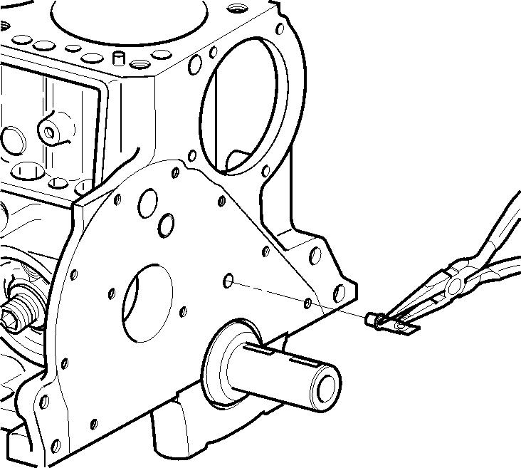
2. Use the J 6978-E in order to remove the crankshaft sprocket.
3. If necessary, remove the crankshaft keys.
Installation Tools Required
•J 5590 Crankshaft Sprocket Installer
1. Install the keys into the crankshaft keyways.
2. Use the J 5590 in order to install the crankshaft sprocket.
3. Install timing gear cover See “Timing Gear Cover” on page46

Harmonic Balancer Installation1. Coat oil seal contact area on harmonic balancer with engine oil. Position hub over crankshaft and key, and start hub into position with a mallet. Using tool J-8792, drive hub onto crankshaft until it bottoms against crankshaft gear.
NOTE!Crankshaft extends slightly through hub and a hollow tool is necessary to drive hub completely into bottomed position.
NOTE!There are two 3/8 in. (9.925 mm) holes and one 5/16 in. (7.938 mm) hole that must be matched on hub in order to properly position timing mark.
2. Install circulating pump pulley.

3. Install alternator and power steering belts and adjust to specifications.
4. Install front engine mount.
5. Fill engine crankcase with proper amount of oil.
6. Lake or tank test unit and check for leaks.
Camshaft
Measuring Camshaft LiftNOTE!Remove both connectors from ignition coil. If improper valve operation is indicated, measure the lift of each push rod in consecutive order and record the readings.
1. Remove valve cover and rocker arms.
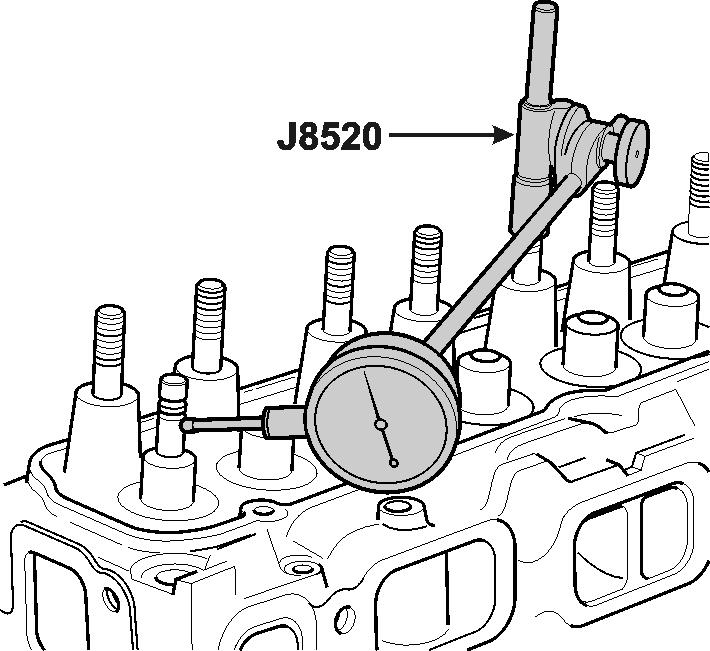
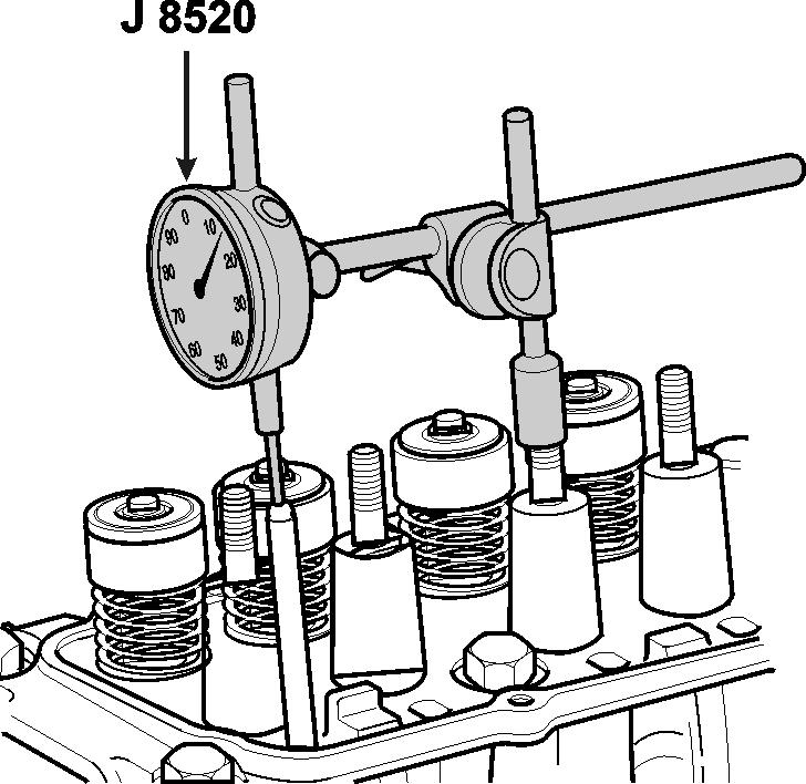
2. Position indicator with ball socket adapter (tool J8520) on push rod.
3. Rotate crankshaft slowly in the direction of rotation until the lifter is on the heel of the cam lobe. At this point, the push rod will be in its lowest position.

4. Set dial indicator on zero. Rotate the crankshaft slowly, or attach an auxiliary starter switch and “bump” the engine over, until the push rod is in the fully raised position.
5. Compare the total lift recorded from the dial indicator with specifications. The correct lift is 0.25294 inch ± 0.001 inch (6,4247 ± 0,0254 mm).
6. Continue to rotate the crankshaft until the indicator reads zero. This will be a check on the accuracy of the original indicator reading.
7. If camshaft readings for all lobes are within specifications, remove dial indicator assembly. Install and adjust valve mechanism.
Removal1. Withdraw oil from crankcase. Drain coolant from block and exhaust manifold.
2. Remove valve cover and gasket. Loosen valve rocker arm nuts and pivot rocker arms clear of push rods.
3. After noting position of rotor, remove distributor.
4. Remove coil, side cover, and gasket. Remove push rods and valve lifters.
5. Remove crankshaft pulley and hub. Disconnect oil drain tube. Remove oil pan and timing gear cover.
6. Remove two camshaft thrust plate screws by working through holes in camshaft gear.
7. Remove the camshaft and gear assembly by pulling it out through the front of the block.
NOTE!Support shaft carefully when removing so as not to damage camshaft bearings.
Inspection The camshaft has three bearings, all with the same journal diameter of 1.8677 in. to 1.8697 in. (47,440 to 47,490 mm). These dimensions should be checked with a micrometer for an out-of- round condition. If the journals exceed 0.001 in. (0,025 mm) out-of-round, the camshaft should be replaced.
The camshaft should also be checked for alignment. The best method is by use of “V” blocks and a dial indicator. The dial indicator will indicate the exact amount that the camshaft is out of true. If it is out more than 0.002 in. (0,051 mm) dial indicator reading, the camshaft should be replaced. When checking, the high reading of the dial indicator indi-
Gear and Thrust Plate cates the high point of the shaft. Examine the camshaft bearings and if any bearing needs replacement, replace all bearings.
If the inspection indicated that the camshaft, gear and thrust plate were in good condition, the camshaft end play should be checked. This clearance should be 0.003 in. to 0.008 in. (0,0762 to 0.2032 mm).
860028
Disassembly
If the inspection indicated that the shaft, gear or plate should be replaced, the gear must be removed from the shaft. Support the camshaft gear and press shaft out of gear.
NOTE!Thrust plate must be positioned so that woodruff key in shaft does not damage it when shaft is pressed out of gear. Also, support the hub of the gear or the gear will be seriously damaged.

860029
8. Inspect the crankshaft and camshaft sprockes for the following:

•The camshaft and crankshaft sprockets for wear.
•One edge of worn teeth or that are no longer concentric.
•The valley between worn teeth.
•The keys and crankshaft keyways for wear.
Camshaft and Bearings Clean and Inspect
Tools Required
•J 7872 Magnetic Base Indicator Set
Caution! Wear safety glasses.
1. Clean the camshaft in solvent.
2. Dry the camshaft with compressed air.
3. Inspect the camshaft bearing journals for scoring or excessive wear.
4. Inspect the camshaft valve lifter lobes for scoring or excessive wear.
5. Inspect the camshaft retainer plate for wear.
6. Inspect the camshaft bearings for proper fit in the engine block. Camshaft bearings have an interference fit to the engine block and should not be loose in their engine block bearing bores.
7. 7.Inspect the camshaft bearings for excessive wear or scoring. Bearings with excessive wear or scoring must be replaced.
8. Measure the camshaft for out-of-round, taper or undersize with a micrometer. Refer to Engine Mechanical Specifications.
9. Support the camshaft front and rear journals on V-blocks.
10. Measure the camshaft run-out at the intermediate journal with J 7872. Refer to Engine Mechanical Specifications.
11. Replace camshaft if measurements are not within specifications.
Camshaft Bearings
Assembly To assemble camshaft gear thrust plate and gear spacer ring to camshaft, proceed as follows:

1. Firmly support shaft at back of front journal in an arbor press. Place gear spacer ring and thrust plate over end of shaft, and install woodruff key in shaft keyway.
2. Install camshaft gear and press it onto the shaft until it bottoms against the gear spacer ring. The end clearance of the thrust plate should be 0.003-0.008 in. (0,0762-0,2032 mm)
Removal Camshaft bearings can be replaced while the engine is disassembled for overhaul, or without complete disassembly of the engine after camshaft and flywheel have been removed. Operation is easier if crankshaft is also removed. See Crankshaft in this section.
1. With camshaft and flywheel removed, drive out expansion plug for rear cam bearing by driving from inside.
2. Position bearing pilot in inner bearing. Install nut on puller screw far enough so puller screw can be threaded into pilot while nut extends out front of block.
3. Install remover section onto puller screw, and then install screw through cam bore and thread it into pilot.
4. Using two wrenches, hold screw shaft and turn puller nut to remove bearing.
5. Remove pilot from shaft and install on drive handle with shoulder to handle. Drive out front and rear bearings from outside to inside of block.
Installation Tools Required
•J 6098-01 Camshaft Bearing Installer NOTE!
•A loose camshaft bearing may be caused by an enlarged, out of round or damaged engine block bearing bore.
•The outer front and rear camshaft bearings must be installed first. These bearings serve as guides for the tool pilot and help center the inner bearings during the installation process.
•The camshaft bearing oil holes must align with the oil galleys in the engine block. An improperly aligned camshaft bearing oil galley hole will restrict oil flow to the bearing and camshaft journal.
1. Use the J 6098-01 in order to install the front and rear camshaft bearings: a. Assemble the bearing tool to the driver handle. b. Align the oil holes. c. Drive the front and the rear camshaft bearings inward toward the center of the engine block.
2. Use the J 6098-01 in order to install the inner camshaft bearings. Repeat the following steps for each of the inner camshaft bearings: a. With the nut (4) and the thrust washer (3) installed to the end of the puller screw threads, index the pilot in the camshaft front bearing and install the puller screw through the pilot (2). b. Index the camshaft bearing in the bore. Make sure you align the oil galley holes. c. Install the puller screw through the bearing bore and bearing to be installed and assemble bearing tool (1) to the puller screw with the shoulder toward the bearing. Make sure that enough threads are engaged. d. Using two wrenches, hold the puller screw (5) while you turn the nut in order to draw the bearing into the bore. When the bearing has been pulled into the bore, remove the bearing tool and the puller screw and check the alignment of the bearing oil hole to the bore oil hole.
3. Install a new camshaft rear bearing hole plug. Coat the plug outside diameter with GM P/N 1052080 sealant, or the equivalent.
Camshaft Installation1. If crankshaft has been removed, install it at this time. Follow procedures under the title Crankshaft in this section. If a new camshaft is to be installed, coat cam lobes with GM Super Engine Oil Supplement (G.M. P/N 1051858) and add rest of can to crankcase oil.
2. Install the camshaft assembly in the engine block, being careful not to damage bearings or cam.
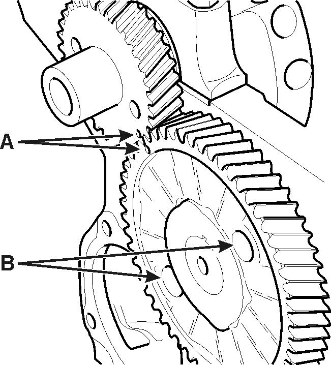
3. Turn crankshaft and camshaft so that the valve timing marks A on the gear teeth will line up, then push camshaft into position. Install camshaft thrust plate to block screws (B: screw access holes) and tighten them to 80 in. lb. (9 N.m).
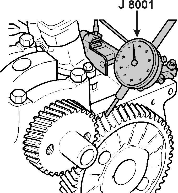
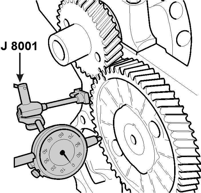
4. Check camshaft and crankshaft gear runout with a dial indicator J8001. The camshaft gear runout should not exceed 0.004 in. (0.102 mm) and the crankshaft gear runout should not exceed 0.003 in. (0.076 mm).
5. If gear runout is excessive, the gear will have to be removed, and any burrs cleaned from the shaft or the gear replaced.
6. Check the backlash between the timing gear teeth with a narrow feeler gauge or dial indicator J8001. The backlash should not be less than 0.004 in. (0,102 mm) nor more than 0.006 in. (0.152 mm).
7. Install timing gear cover with new gaskets. Install oil pan with new gaskets and sealer. Connect oil drain tube.
8. Install harmonic balancer as described under title Timing Gear Cover in this section.
9. Install valve lifters and push rods. Install side cover with a new gasket and sealer. Attach coil and wires. Install distributor, positioning rotor to reference mark.
10. Pivot rocker arms over push rods. Adjust valve lash as outlined under heading Valve Lash Adjustment.
11. Add oil to engine. Install the alternator and power steering belts, then adjust tension. Check and adjust timing.
Crankshaft
Crankshaft and Bearings Clean and Inspect (Connecting Rod Bearing Clearance)
NOTE!Connecting rod bearings are a precision insert type. Connecting rods are of a powdered metal design and cannot be shimmed or filed for bearing fit. If clearances are found to be excessive, a new bearing and/or connecting rod are required. Do not rotate the crankshaft while gauging plastic is between the crankshaft journal and the bearing surface.
1. Remove the connecting rod nuts.
2. Remove the connecting rod cap and bearing.
3. Inspect the crankshaft bearings for craters or pockets. Flattened sections on the bearing halves also indicate fatigue.
4. Inspect the crankshaft bearings for excessive scoring or discoloration.
5. Inspect the crankshaft bearings for dirt or debris imbedded into the bearing material.
6. Install the gauging plastic (1) onto the connecting rod bearing journal. Install the gauging plastic the full width of the journal.
7. Install the connecting rod cap and bearing. Tighten the nuts evenly to 61 N•m (45 lb ft).
8. Remove the connecting rod nuts.
9. Remove the connecting rod cap and bearing.
10. Measure the gauging plastic at its widest area using the scale supplied with the plastic gauging kit.
11. Compare the measurements to Engine Mechanical Specifications.
Crankshaft , Bearings and Bearing Cap Removal
1. Remove the crankshaft bearing cap bolts.
2. Remove the crankshaft bearing caps.
3. Remove the crankshaft.
4. Remove the crankshaft bearings from the bearing caps and from the engine block.
Crankshaft and Bearings Clean and Inspect Tools Required •J 7872 Magnetic Base Indicator Set
Caution: Wear safety glasses in order to avoid eye damage.
1. Clean the crankshaft in solvent.
2. Inspect the crankshaft oil passages for restrictions.
3. Dry the crankshaft with compressed air.
4. Inspect the crankpins for scoring or wear.
5. Inspect the crankshaft bearings for craters or pockets. Flattened sections on the bearing halves also indicate fatigue.
6. Inspect the crankshaft bearings for excessive scoring or discoloration.
7. Inspect the crankshaft bearings for dirt or debris imbedded into the bearing material.
8. Inspect the crankshaft bearings for improper seating indicated by bright, polished sections of the bearing.
•If the lower half of the bearing is worn or damaged, both the upper and lower halves must be replaced.
9. Measure the crankpins for out-of-round, taper or undersize with a micrometer. Refer to Engine Mechanical Specifications.
10. Support the crankshaft front and rear journals on V-blocks.
11. Measure the crankshaft run-out at front and rear intermediate journals with J 7872. Refer to Engine Mechanical Specifications.
12. Replace or recondition crankshaft if measurements are not within specifications.
Crankshaft and Bearings Clean and Inspect (Main Bearing Clearance)
NOTE!Crankshaft main bearings are a precision insert type. Main bearing caps are machined with the engine block for proper clearance and cannot be shimmed or filed for bearing fit. Crankshaft bearing clearances are critical. If the clearances are found to be excessive, new bearings and/ or engine block and cap repair may be required.
NOTE!Do not rotate the crankshaft while gauging plastic is between the crankshaft journal and the bearing surface.
1. Remove the crankshaft bearing cap bolts.
2. Remove the crankshaft bearing caps.
3. Install gauging plastic (1) onto the crankshaft journal. Install the gauging plastic the full width of the crankshaft bearing journal.
4. Install the bearing, bearing cap and bolts. Tighten the crankshaft bearing cap bolts to 88 N•m (65 lb ft).
5. Remove the crankshaft bearing cap bolts.
6. Remove the crankshaft bearing caps.
Crankshaft, Bearings and Bearing Cap Installation
7. Measure the gauging plastic at its widest area using the scale supplied with the plastic gauging kit.
8. Compare the measurements to Engine Mechanical Specifications.
•If the gauging plastic shows irregularity in the journal exceeding 0.025 mm (0.001 in), remove the crankshaft and measure the journal with a micrometer.
•If the clearance is greater than Engine Mechanical Specifications, select and install an undersized bearing set. Measure the clearance with gauging plastic.
•If clearance cannot be brought to specifications, grind the crankshaft for use with the next undersized bearing.
9. Use a dial indicator or feeler gauge in order to measure end play between the front of the rear of the crankshaft bearing cap and the crankshaft thrust surface in order to determine the crankshaft end play.
10. If you use a feeler gauge, measure between the thrust surface of the crankshaft bearing and the crankshaft. Refer to Engine Mechanical Specifications.
NOTE!
•Crankshaft bearing caps must be installed to the proper location and direction.
•When installing the crankshaft bearings, align the locating tabs on the bearings with the locating notches in the engine block journal bore and the bearing cap.
•Always install crankshaft bearings with their machined partner. Do not file bearings or mix bearing halves.
1. Install the crankshaft bearings into the engine block and the crankshaft bearing caps.
2. Coat the crankshaft bearings with clean engine oil.
3. Install the crankshaft.
4. Install the crankshaft bearing caps with the crankshaft bearings.
5. Be sure that the cap directional arrows point toward the front of the engine block and the cap is in its original position.
6. Install the crankshaft bearing cap bolts.
7. Thrust the crankshaft rearward in order to set and align the thrust bearings and the bearing caps.
8. Thrust the crankshaft forward in order to align the rear faces of the rear crankshaft bearings.
9. Tighten all of the bolts to 88 N•m (65 lb ft).
Crankshaft Rear Oil Seal and Housing
Removal1. Remove the crankshaft rear oil seal housing bolts.
2. Remove the crankshaft rear oil seal housing, seal and gasket.
Rear Main Bearing Oil Seal Replacement NOTE!Care should be taken when removing the rear crankshaft oil seal so as not to nick the crankshaft sealing surface.
VE045-3L VE043-3L DR1878
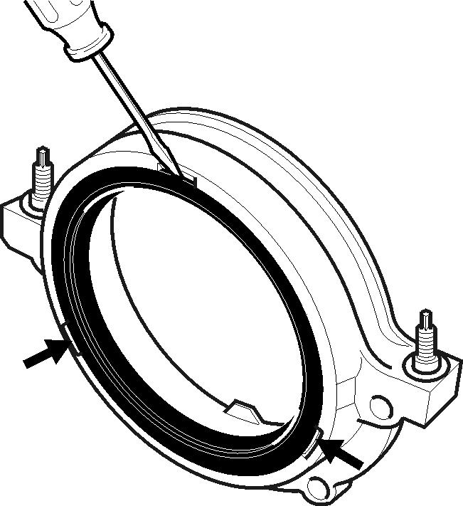
1. Insert a screwdriver into the notches provided in the seal retainer and pry the seal out. Take care not to damage the crankshaft sealing surface.
2. Inspect chamfer on crankshaft for grit, loose rust, and burrs. Clean seal running surface on the crankshaft with a non-abrasive cleaner.
3. Lubricate the inner and outer diameter of new seal with engine oil. Install the seal on J-35621. Position J-35621 against the crankshaft. Thread the attaching screws into the tapped holes in the crankshaft.
4. Tighten screws securely. This will ensure the seal is installed squarely over the crankshaft. Turn handle until it bottoms then remove J-35621
Crankshaft Rear Oil Seal and Housing
Installation Tools Required
•J 35621 Crankshaft Rear Oil Seal Installer
NOTE!Always use a new crankshaft rear oil seal and new crankshaft rear oil seal housing gasket when you install the crankshaft rear oil seal housing.
1. Install the new gasket and the crankshaft rear oil seal housing on to the studs.
2. Install the rear oil seal housing nuts and bolts.
3. Tighten the crankshaft rear oil seal housing nuts and bolts to 15 N•m (135 in lb).
4. Coat the new oil seal entirely with clean engine oil.
5. Install the seal onto the J 35621.
6. Install the J 35621 onto the rear of the crankshaft. Tighten the screws snugly in order to ensure that the seal will be installed squarely over the crankshaft.
7. Install the crankshaft rear oil seal onto the crankshaft and into the crankshaft rear oil seal housing. Tighten the wing nut on the J 35621 until the oil seal bottoms.
8. Remove the J 35621 from the crankshaft rear oil seal housing.

Oil Seal Retainer Replacement
1. Remove Flywheel and oil pan. Remove screws, nuts and seal retainer. Remove gasket.
2. Remove rear crankcase oil seal as previously stated and clean gasket surfaces on block and seal retainer.
NOTE!Whenever seal retainer is removed, a new retainer gasket and rear crankshaft oil seal must be installed.
3. Attach gasket to block. No sealer is required. Install seal retainer, screws and nuts. Tighten to 135 in. lb. (15 N•m).
4. Install oil pan. Install rear crankshaft oil seal as outlined previously. Install flywheel.
Piston and Connecting Rod
Piston and Rod Removal
1. Withdraw crankcase oil. Disconnect oil drain tube. Remove oil pan.
2. Drain coolant from block and exhaust manifold, then remove cylinder head.
Removal Tools Required
•J 5239 Connecting Rod Guide Tool
•J 24270 Ridge Reamer
1. Remove the ring ridge as following:
2. Turn the crankshaft until the piston is at the bottom of the stroke.
3. Place a cloth on top of the piston.
4. Use the J 24270 to remove the cylinder ring ridge.
5. Turn the crankshaft so the piston is at the top of the stroke.
6. Remove the cloth.
7. Remove the cutting debris.
NOTE!Place matchmarks or numbers on the connecting rods and the connecting rod caps. Upon removal of the piston and connecting rod assembly, install the connecting rod caps to the matching connecting rods.
8. Remove the connecting rod nuts.
9. Remove the connecting rod cap.
10. Remove the connecting rod bearings.
•Keep bearings with the original connecting rod and connecting rod cap.
•Wipe the oil from the bearings.
•Wipe the oil from the crankpins.
11. Use the J 5239 in order to remove the connecting rod and the piston out of the engine block.
12. Use a hammer and tap lightly on the end of the connecting rod guide tool to remove the piston and connecting rod assembly from the cylinder bore.
Disassemble Tools Required
•J 24086-C Piston Pin Removal Set
1. Remove the piston rings from the pistons.
2. Remove the pin from the piston. Caution!
After the J 24086-C Installer bottoms on the support assembly, do not exceed 34,475 kPa (5000 psi) or the tool may be damaged.
Clean and Inspect1. Clean the piston ring grooves with a groove cleaner. Note!Clean varnish from piston skirts and pins with a cleaning solvent. DO NOT WIRE BRUSH THE PISTON SKIRT. Clean the ring grooves with a groove cleaner, and make sure oil ring holes and slots are clean.
Inspect the piston for cracked ring lands, skirts or pin bosses, wavy worn ring lands, scuffed or damaged skirts, or eroded areas at top of the piston. Replace pistons that are damaged or otherwise show signs of excessive wear.
Caution! Wear safety glasses.
2. Clean the connecting rod in cleaning solvent.
3. Clean the varnish from the piston skirts and the pins with cleaning solvent
4. Dry the components with compressed air.
5. Do not use a wire brush in order to clean any part of the piston.
6. Clean the piston oil ring holes and the slots.
7. Inspect the connecting rod for twisting, nicks and cracks. Replace any damaged connecting rods.
8. Inspect the pistons for the following conditions: a. The piston pin bores and the piston pins must be free of varnish or scuffing when being measured. b. Use a micrometer in order to measure the piston pin. c. Use an inside micrometer in order to measure the piston pin bore. Replace the piston and piston pin if the clearance is in excess of 0.0254 mm (0.001 in). d. Match the piston and piston pin. Do not service separately. a. Place the compression ring into the cylinder bore. b. Push the compression ring into the cylinder bore approximately 6.5 mm (0.25 in) above the ring travel. The ring must be square to the cylinder wall. c. Use a feeler gauge in order to measure the end gap. d. Select another size ring set if the end gap exceeds specifications. a. Roll the piston ring entirely around its ring groove on the piston. b. Dress the groove with a fine cut file if the ring groove causes binding. c. Replace the piston ring if a distorted piston ring causes binding. d. Use a feeler gauge in order to measure the side clearance of the piston ring and groove. e. Try another piston ring if the side clearance is too small.
•Cracked ring lands, skirts or pin bosses.
•Nicks or spurs in the grooves that may cause binding.
•Warped or worn ring lands.
•Scuffed or damaged skirts.
•Eroded areas at the top of the piston.
•Worn piston bores and piston pins.
9. Replace pistons that are damaged or show signs of excessive wear.
10. Measure the pin bore-to-piston clearance.
11. Measure the piston compression ring end gap. NOTE!Fit each compression ring to the cylinder in which it will be used.
12. Measure the piston ring side clearance.
Piston SelectionNOTE!Measurements of all components should be taken with the components at normal room temperature.
For proper piston fit, the engine block cylinder bores must not have excessive wear or taper.
A used piston and pin set may be reinstalled if, after cleaning and inspection, they are within specifications.
1. Inspect the engine block cylinder bore. Refer to Cylinder Block Clean and Inspect.
2. Inspect the piston and piston pin. Refer to Piston and Connecting Rod Clean and Inspect.
3. Use a boring gauge in order to measure the cylinder bore diameter at a point of 66 mm (2.5 in) from the top of the cylinder bore.
4. Measure the bore gauge with a micrometer and record the reading.
5. With a micrometer or caliper at a right angle to the piston, measure the piston 11 mm (0.433 in) from the bottom of the skirt.
6. Subtract the piston diameter from the cylinder bore diameter in order to determine piston-to-bore clearance.
7. For proper piston-to-bore clearance, Refer to Engine Mechanical Specifications.
8. If the proper clearance cannot be obtained, select another piston and measure for the clearances. If the proper fit cannot be obtained, the cylinder bore may require boring or honing. Refer to Cylinder Boring and Honing.
9. When the piston-to-cylinder bore clearance is within specifications, permanently mark the top of the piston for installation to the proper cylinder.
Assemble Tools Required
J24086-C
•J 24086-C Piston Pin Removal Set
NOTE!When assembling the piston and connecting rod, the flange or the heavy side on the connecting rod must face toward the front of the piston (stamped arrow in top of the piston head).
1. Install the piston pin and connecting rod assembly.
•Lubricate the piston pin holes in both the piston and the connecting rod assembly.
•Press the piston pin into the piston and connecting rod assembly using the J 24086-C.
•Inspect for freedom of movement of the piston on the piston pin.
2. Install the piston rings onto the piston. The marked side of the piston rings must face toward the top of the piston.
CAD
(A) Oil ring spacer gap
(B) Oil ring gap
(C) Lower compression ring gap
(D) Upper compression ring gap
3. Use the following procedure in order to locate the piston ring gaps
•Install the oil ring spacer in groove and insert anti-rotation tang in oil hole.
•Hold the spacer ends together and install lower oil ring rail with the gap properly located.
•Install the upper oil ring rail with the gap properly located.
•Flex the oil ring assembly to make sure the rings are free.
•Install the lower compression ring.
Installation Tools Required
•J 5239 Guide Set
•J 8037 Piston Ring Compressor
Important
•The piston and cylinder bore have been measured and the bore has been sized for the proper clearance. Install the piston and connecting rod assembly into the proper cylinder bore.
•The piston alignment mark (A) MUST face the front of the engine block.
1. Lubricate the following components with clean engine oil:
•The piston.
•The piston rings.
•The cylinder bore.
•The bearing surfaces.
2. Install the connecting rod bearing into the connecting rod and bearing cap.
3. Install the J 5239 onto the connecting rod.
4. Install the J 8037 or equivalent onto the piston and compress the piston rings.
5. Install the piston assembly into its matched bore with the stamped arrow facing forward.
6. Use the J 8037 and the J 5239 and lightly tap the top of the piston with a wooden hammer handle.
•Hold the J 8037 firmly against the engine block until all of the piston rings enter the cylinder bore.
•Use the J 5239 in order to guide the connecting rod onto the crankshaft journal.
7. Remove the J 5239.
8. Install the connecting rod cap and nuts. Tighten the nuts evenly to 61 N•m (45 lb ft).
Cylinder Block
9. When all of the connecting rod bearings are installed, tap each connecting rod assembly lightly parallel to the crankpin in order to make sure that they have clearance.
10. Use a feeler gauge or a dial indicator in order to measure the side clearance between the connecting rod caps. Refer to Engine Mechanical Specifications.
Clean and Inspect1. Clean the following areas:
•The engine block in solvent, removing all sludge, dirt or debris Caution! Wear safety glasses.
•Dry the block with compressed air.
•The gasket surfaces.
•The coolant passages.
•The oil passages.
•The main bearing caps.
2. Inspect the following areas:
•The cylinder walls for excessive scratches, gouging or ring ridge.
•The coolant jackets for cracks.
•The valve lifter bores for excessive scoring or wear.
•The crankshaft bearing webs for cracks.
•The gasket sealing surfaces for excessive scratches or gouging.
•The oil passages for restrictions.
•All threaded bolt holes for thread damage.
Cylinder Bore Measurements Tools Required
•J 8087 Cylinder Bore Gauge
1. Use the J 8087 in order to check cylinder bore taper and out-ofround as follows: a. Set the gauge so that the thrust pin must be forced in about 1/ 4 in to enter the gauge in the cylinder bore. b. Center the gauge in the cylinder and turn the dial to “0.” c. Work the gauge up and down to determine the taper. d. Turn the gauge to different point around the cylinder to determine the out-of-round condition. Refer to Engine Mechanical Specifications.
Boring Procedure1. Before you start the honing or reboring process, measure all new pistons with the micrometer, contacting at points exactly 90× from the piston pin centerline. Select the smallest piston for the piston fitting See “Piston Selection” on page67 Slightly varied pistons in a set may provide correction, in case the first piston is too loosely fitted.
2. Before you use any type of boring bar, file the top of the cylinder block in order to remove any dirt or burrs. If you do not check the cylinder block, the boring bar may be tilted, this could result in the rebored cylinder wall being at incorrect right angles from the crankshaft.
3. Carefully follow the instructions furnished by the boring bar manufacturer regarding the use of the equipment.
4. When you rebore cylinders, make sure all crankshaft bearing caps are in place. Tighten the bearing caps to the proper torque to avoid distortion of the bores in the final assembly. The crankshaft must be clear of the boring cutter when you bore each cylinder. Cover or tape the crankshaft bearings and other internal parts to protect during the boring or honing process.
Honing Procedure1. When honing the cylinders, follow the Hone manufacturerís recommendations for use, cleaning and lubrication. Use only clean, sharp stones of the proper grade for the amount of material you remove. Dull, dirty stones cut unevenly and generate excessive heat. When using coarse or medium-grade stones, leave sufficient metal so that all stone marks may be removed with the fine stones you use for finishing in order to provide for proper clearance.
2. During the honing process, thoroughly clean the cylinder bore. Check for a correct fit of the piston you select for the individual cylinder.
3. When honing to eliminate taper in the cylinder, make full strokes of the hone in the cylinder. Repeatedly check the measurement at the top, the middle and the bottom of the bore.
Notice!Handle the pistons with care. Do not force the pistons through the cylinder until you hone the cylinder to the cor- rect size. The piston can be distorted through careless handling.
4. When finished honing a cylinder bore to fit a piston, move the hone up and down at a sufficient speed to obtain very fine, uniform surface finish marks in a cross hatch pattern at 45-65 degrees.
5. The finish marks should be clean but not sharp. The finish marks should be free from imbedded particles and torn or folded metal.
6. By measuring the piston to be installed at the sizing point specified and by adding the average of the clearance specification, you can determine the finish hone cylinder measurement. See “Torque Specifications” on page86 Measure the block and the piston at normal room temperature.
7. True up the refinished cylinder bores to have less than the specified out-of-round or taper. You must final hone each bore in order to remove all stone or cutter marks and in order to provide a smooth surface.
8. For piston-to-bore tolerance specifications, See “Torque Specifications” on page86
9. After final honing and before the piston is checked for fit, clean the bores with hot water and detergent. Scrub the bores with a stiff bristle brush and rinse the bores thoroughly with hot water. Do not allow any abrasive material to remain in the cylinder bores. This abrasive material will wear the new rings, the cylinder bores and the bearings lubricated by the contaminated oil. After you wash the bore, brush the dry bore clean with a power-driven fiber brush.
10. Permanently mark the piston for the cylinder to which the piston has been fitted.
11. Apply clean engine oil to each bore in order to prevent rusting.
Distributor Lower Bearing
The distributor lower bearing is a bronze bushing pressed into the lower side of the engine block. Its upper inside diameter pilots the distributor shaft, and the outside diameter extending below the block pilots the oil pump.
Some engines have a thrust washer at the upper end of the bushing bore. The thrust washer, where used, may be replaced at the same time the bushing is replaced.
The lower bushing will ordinarily require only a clearance or wear check during engine overhaul. When distributor shaft-to-bushing clearance exceeds 0.0035 in. (0,0889 mm) the bushing should be replaced as follows with oil pump and distributor removed:

Removal Tools Required
•J 9534 Distributor Lower Bushing Remover
•J 6585 Slide Hammer
1. Install tool J-9534 into bushing and using a slide hammer, remove the bushing.
CAUTION!
Protect your eyes from fragments. Wear safety glasses when striking these tools, handles, drivers, etc. Tool end may mushroom after being repeatedly struck. Always grind off any rolled edges before using tool. Use soft face hammers whenever possible.
2. Using a drift up through bushing bore, drive thrust washer (if installed) out of bore and remove from block.
3. Clean bushing bore in block and check for burrs or damage.
Installation4. If thrust washer was removed, start new washer in position in bore and drive into place using tool J-9535.
5. Using tool J-9535 with driver-bolt in driver handle, install driver into new bushing from large inside diameter.
6. Place bushing and driver on block and drive the bushing in position. Depth is determined by tool bottoming against the block.
7. Remove tool from bushing. It is possible that the bushing with minimum I.D. will collapse enough, during installation, to slightly seize the installer arbor. If this happens, remove installer tool using slide hammer in driver bolt hole of driver handle.
NOTE!This will not damage the bushing and the tool is designed for this purpose, should it occur.
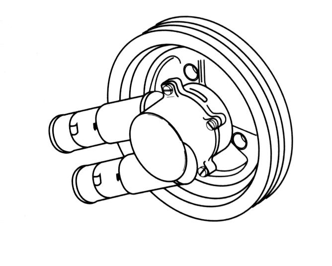
Circulating Pump
Removal1. Remove drain plugs on port side and drain coolant from block and exhaust manifold. Disconnect water hose from circulating pump.
2. Loosen four screws holding circulating pump pulley to circulating pump.
3. Remove the serpentine belt. Remove circulating pump pulley and bolts. Unscrew bolts and remove the circulating pump from the engine.
NOTE!Pull the pump straight out of the block first, to avoid damage to impeller.
Inspection If the seal is leaking replace the pump. If the bearing is rough or allows excessive sideways movement of the shaft, replace the pump. If the impeller has excessive erosion replace the pump.
4. Inspect the circulating pump for the following:
•Gasket sealing surfaces for excessive scratches or gouges.
•Excessive side-to-side play in the pulley shaft.
•Leakage at the water inlet housing or rear cover gaskets areas.
•Leakage at the water pump vent hole.
•A stain around the vent hole is acceptable. If leakage occurs at the vent hole with the engine running and the cooling system pressurized, replace the pump.
InstallationNOTE!This pump has a special shaft and bearing assembly and a special seal assembly intended for marine service. Do not substitute with an automotive pump.
1. Apply Volvo Penta Gasket Sealing Compound to a new pump to block gasket. Install pump assembly on cylinder block and tighten bolts to 20 N•m (15 ft. lb.)
2. Install circulating pump pulley. Install serpentine belt.
3. Connect coolant hoses to circulating pump. Install the drain plugs in the engine block and exhaust manifold. Tighten the plugs securely. Test the unit and check for leaks.
Oil Pan Replacement
Oil Dipstick Tube Removal1. Remove oil using a suction pump.
2. Remove oil dipstick tube.
3. Remove the oil pan bolts.
4. Remove the oil pan.
5. Remove the gasket.
6. Discard the gasket.
InstallationNOTE!Apply the sealer 25 mm (1.0 in) in either direction of the radius cavity of the junctions.
1. Apply a small amount of sealer, GM P/N 1052914 or equivalent, 10 mm (0.393 in) wide and 20 mm (0.787 in) long at the engine front cover to engine block junction.
2. Apply a small amount of sealer, GM P/N 1052914 or equivalent, 25 mm (1.0 in) long at the crankshaft rear oil seal housing to engine block junction.
3. Install the new oil pan gasket.
4. Install the oil pan.
5. Install the nuts and bolts to the oil pan.
6. Tighten the rear oil pan nuts to 18.6 N•m (165 in lb).
7. Tighten the oil pan bolts to the crankcase to 9 N•m (80 in lb).
8. Tighten the oil pan bolts to the front cover to 5 N•m (45 in lb).
9. Tighten the oil pan studs to the oil seal retainer to 1.7 N•m (15 in lb).
Oil Pump
OperationThe oil pump consists of two gears (A) and a pressure relief valve (B) enclosed in a two-piece housing (C). The pump is driven from the distributor driveshaft which in turn is driven by a helix gear on the camshaft.
The oil pump is flange mounted to the cylinder block with two bolts, and piloted on the outside of the lower distributor bronze bearing. Oil pressure passes through an opening in the mounting flange to the cylinder block, then into the full flow oil filter. The pump cover is equipped with the pressure regulator valve that regulates oil pressure at approximately 40-60 PSI (135.1-202.6 kPa) at 2000 RPM. The pump intake is of the fixed screen type. A mesh screen (D) filters out small particles of dirt and sludge which may be present.

NOTE!A baffle incorporated on the intake screen has been designed to eliminate pressure loss due to sudden surging stops, turns, and acceleration.
In the event that a screen becomes plugged a steel grommet opens and bypasses oil to the pump.
Removal and Disassembly1. Drain the oil. Disconnect oil withdrawal tube. Remove screws, oil pan and gasket. Remove oil withdrawal tube fitting from oil pan.
2. Remove oil pickup tube clamp bolt. Remove two flange mounting bolts. Remove pump and screen as an assembly.
3. Remove the cover bolts.
4. Remove the pump cover.
5. Remove the drive gear (2) and the driven gear (1). Matchmark the gear teeth for assembly.
6. Remove pressure regulator valve and valve parts. If necessary, remove oil pump suction pipe and screen by pulling from pump housing.
7. Wash all parts in cleaning solvent and dry using compressed air.
Clean and InspectNOTE!The internal parts of the oil pump are not serviced separately. If the oil pump components are worn or damaged, replace the oil pump as an assembly.
The oil pump pipe and screen are to be serviced as an assembly. Do not attempt to repair the wire mesh portion of the pipe and screen assembly.
1. Clean all of the parts in cleaning solvent. Caution: Wear safety glasses.
2. Dry the parts with compressed air.
3. Inspect the following areas:
•The oil pump housing and cover for cracks, scoring, casting imperfections and damaged threads.
•The drive gear shaft (If the shaft is loose in the oil pump housing, replace the oil pump).
•The pressure relief valve for scoring and sticking (Burrs may be removed with a fine oil stone).
•The pressure relief valve spring for loss of tension.
•The oil pump screen for broken wire mesh or looseness (If the pipe is loose or has been removed from the screen, the oil pump screen must be replaced).
•The gears for chipping, galling and wear.
NOTE!If the drive gear and driveshaft are worn, replace the entire oil pump.
•The drive gear and driveshaft for looseness and wear.
Assemble Tools Required
•J 21882 Oil Suction Pipe Installer
NOTE!Replace the pressure relief valve spring when you reuse the oil pump.
1. Install the following items: a. If removed, replace the oil pump screen. The oil pump screen must have a good press fit into the oil pump body. b. Mount the oil pump in a soft jawed vise. c. Apply sealer to the end of the pipe. d. Use the J 21882 and a soft-faced hammer in order to tap the oil pump screen into the pump body. The screen must align parallel with the bottom of the oil pan when it is installed. NOTE!Oil pump should slide easily into place. If not, remove and relocate slot or determine other problem.
•The pressure relief valve (2).
•The pressure relief valve spring (3).
•The retaining pin (1).
2. Coat the drive gear, the driven gear and the housing gear surfaces with clean engine oil.
3. Install the drive gear (2) and the driven gear (1) into the pump body. Align the matchmarks on the gears. Install the smooth side of the gear toward the pump cover.
4. Install the pump cover.
5. Install the cover bolts. Tighten the bolts to 8 N•m (72 in lb).
6. Inspect the pump for smoothness of operation by turning the oil pump driveshaft by hand.
7. Install the oil pump screen.
Oil Dipstick Tube Installation8. Attach and tighten oil pickup tube clamp.
9. Install oil pan using new gaskets and seals.
10. Install withdrawal tube fitting to pan; leave screw loose. Orient fitting and attach withdrawal tube. Then tighten both fitting screw and flare nut to 15-18 ft. lb. (20-24 N•m).
11. Fill crankcase with oil.
Oil Filter Bypass Valve
Inspection Remove the oil filter and check the spring and fiber valve for operation. Check for a cracked or broken valve.
Replacement If replacement is necessary:
1. Remove the valve by prying it out with a screwdriver.
2. Install a new valve and seat it by tapping into place using a 9/16 in. thin wall deep socket and hammer.
3. Install oil filter according to manufacturer’s instructions.

Exhaust Elbow Replacement
Removal1. Loosen all four hose clamps. Lubricate exhaust pipe with a soapy water solution, and slide hose down off exhaust elbow.
2. Loosen hose clamp and disconnect cooling hose from inside of exhaust elbow. Then remove hose fitting.
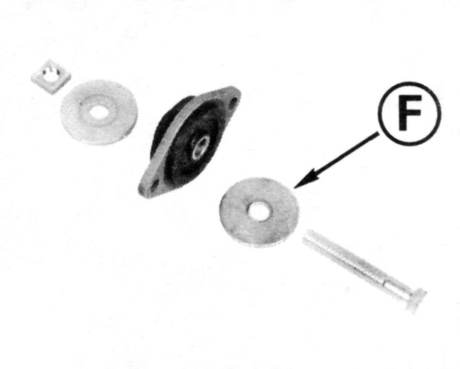
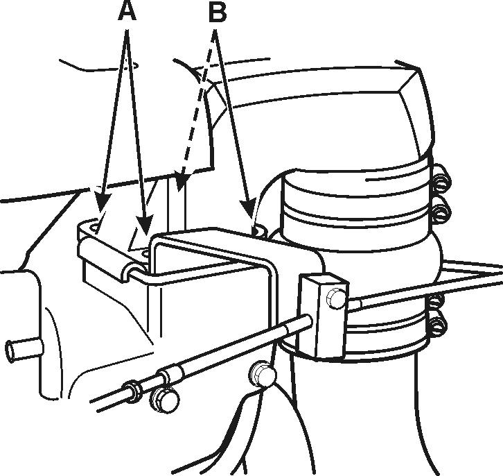
3. Remove the two screws (A) and swing anchor bracket out of the way. Then remove the two nuts and lock washers (B).
4. Loosen the elbow with a soft hammer, then lift it off the manifold. Remove and discard the elbow gaskets. Retain the restrictor plate.
Installation1. Thoroughly clean the manifold and elbow gasket surfaces. Apply Volvo Penta Gasket Sealing Compound to both sides two new gaskets.
2. Sandwich the restrictor plate between the two new gaskets. The slot in the restrictor plate should be positioned inboard toward the engine block. Place the gaskets and restrictor plate on the manifold.
Note!Disregard any stamped markings on the restrictor plate.
3. Mount the elbow on the manifold. Install the throttle anchor bracket, and secure with the two screws (A) and the two nuts and lock washers (B). Tighten all four to 12-14 ft. lb. (16-19 N•m). Slide the exhaust hose all the way onto the elbow.


4. Install hose fitting on the inside of elbow and connect cooling hose.
5. Position the upper clamps in the top two channels and tighten them securely. Position the two lower clamps in the channels and tighten them securely.
6. Reconnect throttle cable to carburetor and throttle linkage plate. Secure with cotter pin.
Exhaust Hose Replacement
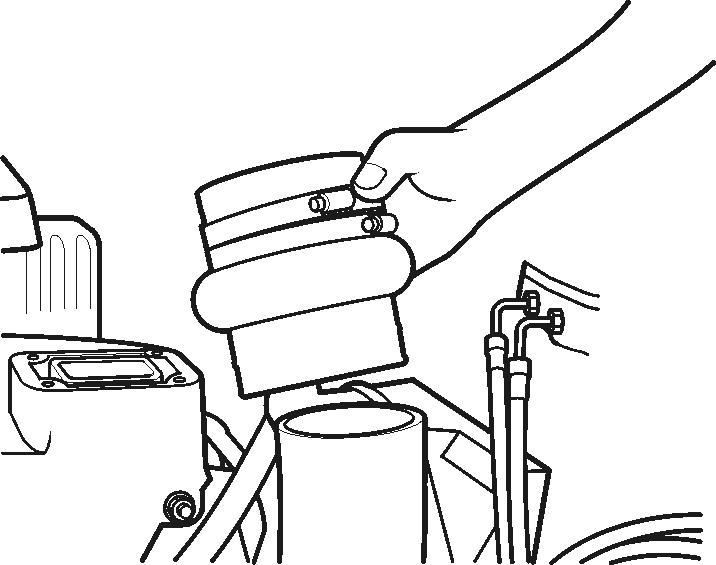
Removal1. Remove high rise exhaust elbow following procedure in High-Rise Exhaust Elbow Replacement.
2. Remove clamps and slide hose off exhaust pipe.
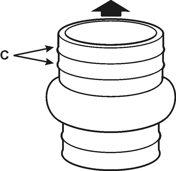
InstallationNOTE!One end of exhaust hose has two ribs C around the circumference. Position this end up when installing hose to ensure secure attachment.
1. Place two No. 64 hose clamps VP P/N 3853791 over exhaust pipe if they were removed.
2. For ease of installation lubricate inside diameter of hose with a soapy water solution, and slide hose all the way onto exhaust pipe. Place two No. 64 clamps VP P/N 3853791 around top section of hose.