3 minute read
Section 2: Engine Mechanical 3.0 Liter


Intake/Exhaust Manifold
Removal1. Disconnect battery cables at battery. Remove throttle cable from anchor block and actuating bracket See “Throttle Cable From Engine” on page123
2. Drain water from block and exhaust manifold See “Draining Engine Block or Exhaust Manifold” on page133
3. Remove carburetor from intake manifold. Follow the instructions in Electrical/Ignition/Fuel Systems Service Manual.
4. Disconnect water hose (A) running between manifold end cap and thermostat housing.
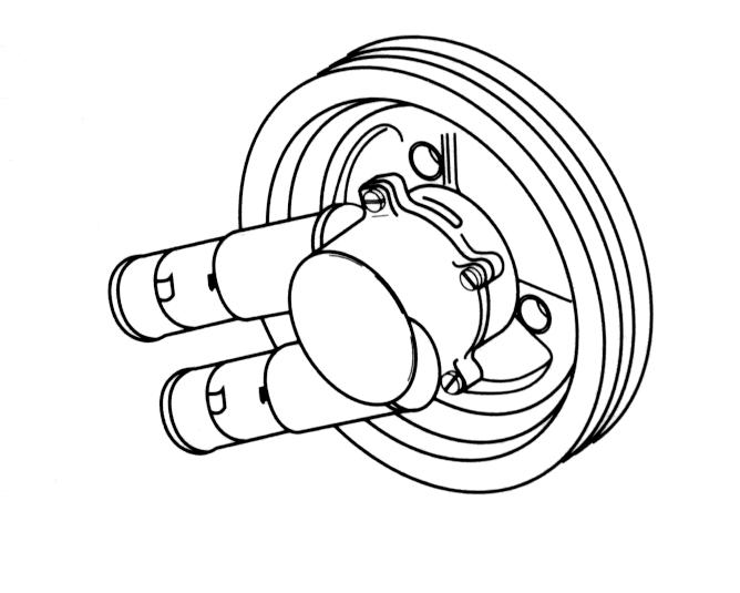
5. Release tension from belt tensioner (B) and remove the serpentine belt. Remove alternator and mounting bracket (C).
Caution!
Remove boat from water before removing exhaust elbow. Water may enter the boat.
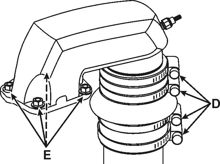
6. Loosen upper hose clamps (D) securing exhaust hose to high rise elbow. Loosen and remove screws and lock washers (E) securing elbow to manifold and remove the throttle linkage plate and elbow.

7. Remove six bolts securing manifold to cylinder head, then pull manifold off of head. Discard gasket.
8. Clean all gasket surfaces of cylinder head and manifold and check for cracks on the manifold casting.
Installation1. Position a new gasket over the manifold studs on the head. Use a gasket sealer if leakage has occurred. Carefully install the manifold in position making sure that the gasket is correctly placed.
2. Install six bolts while holding the manifold in place. Tighten bolts finger tight, then alternately tighten to 20-25 ft. lb. (27-34 N•m) working from the center towards the ends.
3. Apply gasket sealer to a new elbow gasket and place it on the manifold. Push the elbow into the exhaust hose, then install the elbow, throttle linkage plate, lock washers, and screws. Tighten the screws to 12-14 ft. lb. (16-19 N•m).
4. Install carburetor using a new mounting gasket following the instructions in Electrical/Ignition/Fuel Systems Service Manual.
Distributor
Install water hose from thermostat housing to manifold ( A)
5. Install alternator with mounting bracket (A). Tighten screws (B) to 26-30 ft. lb. (35-41 N•m). Reinstall belt following the procedures found in the General Information section of this manual. Tighten the alternator screws (C) to 26-30 ft. lb. (35-41 N•m).

6. Reconnect throttle cable to anchor block and actuating bracket. Secure with cotter pin.
7. Connect battery cables. Start engine and check for fuel leaks.
Removal1. Disconnect the secondary ignition wires (1) from the spark plugs and the ignition coil.
2. Disconnect the primary ignition harness (4) from the ignition coil. Do not remove the wires from the distributor unless it is necessary.
3. Remove the distributor hold down bolt (6).
NOTE!Use special tool P/N 888863 on 3.0GL-B and later engines to remove distributor hold down bolt.
4. Remove the distributor (2) and gasket (3).
InstallationNOTE!To ensure correct ignition timing, the distributor must be installed in the correct position. Position the engine at top dead center on number one cylinder. The distributor cap must be removed in order to position the rotor when installing the distributor.
1. Install the distributor (2) and new gasket (3), making sure the distributor rotor is pointing to number one tower on the distributor cap.
2. Install the distributor hold down (5) and bolt (6). Tighten the hold down bolt to 27 N•m (20 lb ft).
NOTE!California Air Resource Board (C.A.R.B.) requires a tamper proof screw on 3.0GL-B model and later engines operated in California.
3. Connect the primary ignition harness (4) to the ignition coil.
4. Connect the secondary ignition wires (1) to the spark plugs and the ignition coil.
5. Set ignition timing, See “Setting Initial Timing” on page56 in Electric, Fuel and Ignition Workshop Manual P/N 7743454.
Ignition Coil
Removal and installation1. Remove the ignition coil bracket attaching bolts.
2. Remove the ignition coil.
3. Install the ignition coil.
4. Install the ignition coil bracket attaching bolts. Tighten the attaching bolts to 22 N•m (16 lb ft).
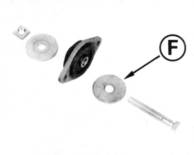
Lift Bracket
Removal and Installation1. Remove the lift bracket bolts.
2. Remove the lift bracket.
3. Install the lift bracket.
4. Install the lift bracket bolts. Tighten the lift bracket bolts to 54 N•m (40 lb ft).
Spark Plug
Removal and Installation1. Clean the area around the spark plug seat with compressed air to prevent dirt from entering the cylinders when the spark plug is removed.
2. Using 5/8 in. spark plug socket, remove spark plug.
3. Set the spark plug gap to 0.045 in (1.14 mm)
4. Install the spark plugs.
5. Tighten the spark plugs to 30 N•m (22 lb ft).
Rocker Arm Cover
Removal1. Remove the rocker arm cover bolts.
2. Remove the rocker arm cover.
3. Remove the gasket.
Installation
1. Install a new rocker arm cover gasket.
2. Install the valve rocker arm cover.
3. Install the rocker arm bolts. Tighten the rocker arm cover bolts to 4.5 N•m (40 lb in).
Pushrod Cover
Removal1. Remove the pushrod cover bolts.
2. Remove the pushrod cover.
3. Remove the gasket.
Installation
1. Install a new pushrod cover gasket.
2. Install the pushrod cover.
3. Install the pushrod cover bolts. Tighten the pushrod bolts to 4.5 N•m (40 lb in).
Valve Rocker Arm and Pushrod
Removal1. 1.Remove the following components from the cylinder head: a. The valve rocker arm nuts (1). b. The valve rocker arm balls (2). c. The valve rocker arms (3).
Installation
2. Install the following components: a. The valve rocker arms (3). b. The valve rocker arm balls (2). c. The valve rocker arm nuts (1).