A
Change Description
Notice (ERN)
B
Location
C
D
E Engineering Release
A = Added D = Deleted
Document Release Status
W = Was
RELEASED Date
Modification Count
See DCN
0
0
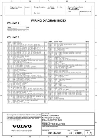
WIRING DIAGRAM INDEX VOLUME 1 NAME PAGE INSTRUCTIONS 2 ABBREVIATION LIST, 24V 6
VOLUME 2 DESCRIPTION Power Supply
AB2−1 Ignition System for Variant DASH−BAS AB2−2 Ignition System for variant DASH−VDV AE1−1 ESS (Energy Storage System) Battery 1 &
AE1−2 ESS Cooling/Heating for Battery 1 & 2
AE1−3 ESS (Energy Storage System) Battery 3 &
AE1−4 ESS Cooling/Heating for Battery 3 & 4 AF1−1 600V System for 4x2 for Single decker AF1−2 600V System for 4x2 for Single decker
AG1−1 AG1−2 AH1 AI1 AJ1 BA1 BB1 BC1
2 3 4
5
FB3
6
HVIL 4x2 Single decker 10 HVIL 4x2 Single decker 11 DC/DC Converter 12 LPC (Low Power Charging) 13 High Power Charging Interface and Heatin 14 VECU (Vehicle ECU) 15 BBM (Body Builder Module) 16 BIO (Bus I/O) 17
JDB
OI1 VD4 XA1 XB1 XC1 XE1−1 XE1−2 XF1 XG1 XH1 XK1 XL1 XX1 YA1−1 YA1−2 YA1−3 YA1−4 ZA1−1 ZA1−2 ZA2−1 ZA2−2
EC1 ED1 EF1 EG1 FA1−1
EBS Steering Angle Sensor Hill Start Aid and Traction Control APBE (Auto Park Brake Evacuation) Parking Brake ECS Supply and Ground
34
35 36 37 38 39 40
EA1−1 EBS (Electronic Brake System) Control 41 EA1−2 EBS (Electronic Brake System) Sensors an 42
The copying, distribution and utilization of this document as well as the communication of its contents to others without expressed authorization is prohibited. Offenders will be held liable for payment of damages. All rights reserved in the event of the grant of a patent, utility model or ornamental design registration.
43 44 45 46 47
57
58
Direction Indicator Designation/Side Marker Lights Brake Lights Park Lights Reverse Lights HVAC (Heat Ventilation Air Condition) 600V Combo Auxiliary Heater
Steering Wheel Switches
59
60 61 62 63 64 65 66
67
Telematics Interface
68
OG1−1 WMECU for Dash−BAS OG1−2 WMECU for Dash−VDV OH1
54 55 56
Windscreen & Headlamp Washer System
Horn Engine Hatch Switch CAN, Backbone 1 CAN, Backbone 2 CAN, Powertrain Subnet 1 CAN, J1939−2−3 CAN, FMS CAN, D−BUS CAN, E−Bus BUS, J1587/J1708 CAN, Powertrain Subnet 2 CAN, F−CAN CAN, DEVCAN for EMD BBI (Body Builder Interface) BBI (Body Builder Interface) BBI (Body Builder Interface) BBI (Body Builder Interface) Ground Ground Safety ground Safety ground
69 70 71
72 73 74 75 76 77 78 79 80 81 82 83 84 XCB401/XCB5 85 XCB801F 86 XCB801F 87 XCB803F 88 89 90 91 92
3
3
Body Heating Valve EM (Electric Motor) & EMD (Electric Moto Gearbox Gear Selector for Full Electric EVU (Extension Valve Unit) Inclination Sensor Gearbox Sensors for Speed and Direction
Fog Lights
53
2
2
CG1−4 CH2 DA4−1 DA4−2 DA4−3 DA4−4
Campaign Lights
JB1
33
CG1−3 Gearbox Oil Pump
GB3
HC1
32
CG1−2 MDS Cooling Fans
Head Lamps
GC1 GC2 GD1 GD2 GD3 HA1
21 22 23 24 25 26 27 28 29 30 31
CG1−1 MDS Cooling System
PAGE 48 49 50 51 52
Air Compressor
GB1
GB2
18 19 20
With Tachograph Without Tachograph Alcolock OBD (On Board Diagnostics) Accelerator pedal HPCU (Hybrid Powertrain Control Unit) CICU (Charging Interface Control Unit) PCM (Powertrain Control Module) OnBC (On Board Charger) CSU (Charging Switch Unit) Chassis Heat Sensors
DESCRIPTION ECS 1st Axle ECS Switches w Marquardt Conn ECS 2nd Axle Air Dryer Air Sensor Wet Tank
FC1 Power Steering GA1−1 SLCM (Light Control Module) Control GA1−2 SLCM (Light Control Module) Control
7 8 9
BD1−1 IC (Instrument Cluster) BD1−2 IC (Instrument Cluster) Control BD1−3 IC (Instrument Cluster) Control
BE1 BE2 BF1 BG1 BI1 BJ1 BM1 BN1 BO1 BP1 CF1
NAME FA1−2 FA2 FA3 FB1 FB2
PAGE 1
1
1
NAME AA2
Document title
WIRING DIAGRAM CHASSIS FOR 790e FULL ELECTRIC BUS 4
4
Document type
PRODUCT SCHEMATICS Owner domain:Document prefix Document No
Issue
70405200
04
Volume
Sheet No
01(03)
1(7) A
B
C
D
E
