1 minute read
Control/computer equipment – 8700


18.9.1 Representation of signal colours
The screen dumps shown in the following section have been modified to improve legibility in black & white print.
WHITE GREEN RED
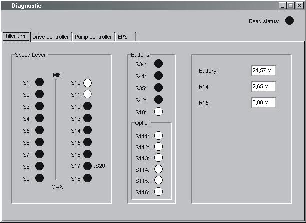
18.9.2 “Tiller arm” tab
Clicking on the tiller arm tab will display a dialogue showing the following:
• Speed lever -the status of the speed control and travel direction selector. The status of each individual hall element is displayed.
• Buttons -The status of the control buttons is displayed. “Sxx” refers to the switch designations as given in the circuit diagram.
• Option -Status of option buttons
• Battery -The measured battery voltage
•R14 -Shows the measured signal voltage from the lift/lower control
• R15 -Not used at present
18.9.3 “Drive Controller” tab (transistor regulator - travel)
Clicking on the Drive Controller tab will display a dialogue showing the following:
•Status of digital inputs and outputs of the transistor regulator. pin refers to the motor controller pin designations as given in the circuit diagram.
• Field PWM - The effective power output supplied to the field circuit as a percentage.
• Armature PWM - The effective power output supplied to the armature circuit as a percentage
• Field current - The current flowing in the field circuit in Amperes.
• Armature current - The current flowing in the Armature circuit in Amperes
• Raw throttle data - The received speed control signal as a percentage.
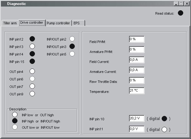
• Temperature - The temperature of the output stage of the transistor controller in degrees Celsius
• Inp pin 10 - The input voltage from the mode/pressure sensor. “digital o” indicates the digital status of the input.
• Inp pin 11-The input voltage from the man-on platform sensor. “digital o” indicates the digital status of the input.