13 minute read
OPERATlON


OPERAT10N
PICTORIAL NOMENCLATURE”.
1NSTRUMENTSANDCONTROLS
ROPSCAB,AIR
CONDIT10NER,RADlO
ThisManualusesthefol10WlngSafetyalertsymboIs・
When you seethose symboIsin thetext,foILowthe SafetymessagetoavoidpersonallnJuryOrdeath・
Failure to fo”ow theinstructionsin the message Willcauseaseriousaccidentordeath, a wARNlNG
Failure to foHow the instrucl:ions in the me$$age might cause a$erious accident or death.
A cAUT10N
Failure to foL10W theinstructionsin the message may cause personal injury or damage to the 10ade「.
PICTORIAL NOMENCLATURE
(ThesketchshowsaModelL40.) lNSlDE THE LOADER
(ThesketchshowsaMode[L27.)
Instrumentsandcontrols
RADlO(SeePage42)
WIPER SVVITCH CT (FRONT)(SeePage25)
WIPER SWITCH (REAR)(SeePage25)
ENGJNESELF-CHECKMON[TO (forL35,L40)(SeePage19)
ENGINE PREHEATING LAMP (SeePage21)
AIR COND[TlONER SWITCH PANEL(SeePage40)
CLUTCH CUT-OFF SVVITCH (SeePage22)
APSSWITCH(OPTlON) (SeePage24)
(SeePage22)
WORK uGHT SWITCH (SeePage23)
Monitors
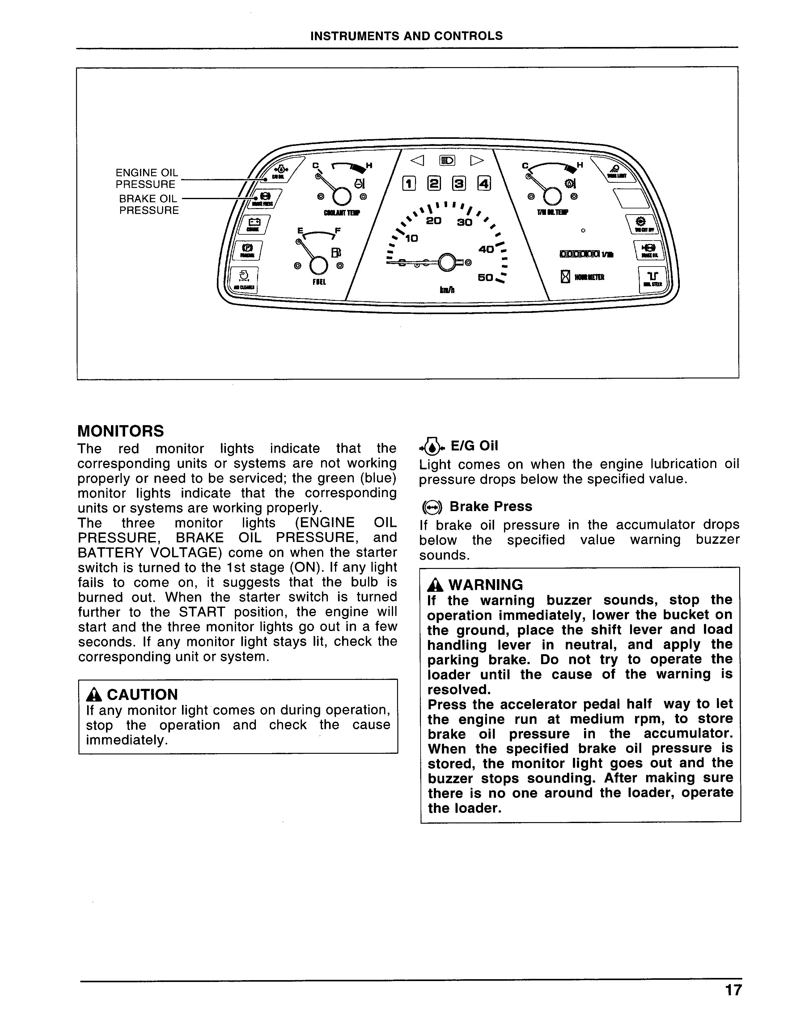
The red monitorlightsindicate that the COrreSPOnding units or systems are not working PrOPerLyorneedtobeserviced;thegreen(bLue) monitorlightsindicate that the corresponding unitsorsystemsareworkingproperly.
・④・E/GOil
Light comes on when the englnelubrication oi[ PreSSuredropsbe10Wthespecifiedvalue・
樹BrakePre$S
The three monitor lights (ENGINE 01L PRESSURE,BRAKE 01L PRESSURE,and BATTERY VOLTAGE)comeon when the starter SWitchisturnedtothelststage(ON).1fanylight fails to come on,it suggests that the bulbis burned out.When the starter switchis turned further to the START position,the englne WiLI Startandthethree monitor]ightsgooutin afew SeCOnds.Lf any monitorlightstayslit,Checkthe COrreSPOndingunitorsystem.
▲cAUTION lfanymonitorlightcomesonduringoperation, StOP the operation and check the cause immediately. lf brake oilpressurein the accumulator drops below the specified value warnlng buzzer SOunds.
AwARNIN? lf the warnlng buzzer sound$,StOP the OPerationimmedjateLy,Lowerthe bucketon the ground,Place the$Mft Lever and10ad handling Leverin neutraL,and apply the Parking brake.Do not try to operate the 10ader untilthe cause of the warningis resoIved.
Pre$S the accelerator pedaL half waytolet the eng]ne run at medium rpm,tO StOre brake oil pressure in the accumulator. When the specified brake oilpressureis StOred,the monitorIight goes out and the buzzer stops sounding.After making sure therei$nO One arOund the10ader,OPerate the10ader.
[ヨCharge
Light comes on when the condition of battery Chargeisinsufficient.
《勘Parking
Light comes on when the parking brake is applied.
むAirCleaner l--■
Light comes on when the air cleaner element becomescIogged.
回画画画(Speedrangeindicator)
Thelampindicatesthespeedranges.

<][>TurnSignalIndicating Light
When the turn slgnatIeveris operated to a turnlng POSition,the corresponding turn slgnal andmonjtorlight(<∬>)comeon. g〉High-beamJndicating Light
Bluelight comes on when the head”ghts arein thehigh-beammode・
ノGworkLight
Greenlight comeswhen the worklightis turned ON.
やT7MCUTOFF
GreenIight comes on when the clutch cut-Off SWitchis turned ON. Turn the clutch cut-Off SWitchwhenstartingoffonanincline.
1「EMG.Steer(Optjonal)
Light comes on when the emergency steering PumPISPutinoperatjon. a WARNlNG
If the emergency $teering sy$tem $tartS OPerating,immediateJymovetoaJevel,Out- Of・trafficareaandrepairthetrouble.
ENG]NESELF-CHECKMONITORLAMPS

(RED,ORANGE)
(L35,L40)
The engine self-Check monitorlamps(red and Oraワge)indicate the operating status of the englneCOntrOlunit. a CAUTloN
JftheorangeIampcomeson:itmeansthatthe englne hasadefect.Theloadercantravelbut the englne has a defect.Contact your authorized dealer.
WhentheenglneStarterSWitchisturnedON,the monitor]amps(red and orange)come on and Stay brjght.If anylamp doesn’t come on,itis SuSPeCted thatthe bulbis b10Wn Out.The[amps WillgooutwhentheengLneStartSnOrma”y.1fthe englne hasanydefectduringoperation,eitherof thelampscomeson・Jfthisisthecase,Parkthe 10aderin an out-Of-traffic area and contact your authorized deaLer.
Whentheprob[emisremedied,themonitor[amp goesout, a WARNlNG lf the englne Sta”$,the steering wheeI becomes hard to turn.Press the brake Pedalquicklytostopthe]oader. a WARNlNG
Ifthe red]ampcomes on:it meansthatthe englne has a defect.The englne might be forced to stall.1n addition,it mjght become difficu[t to contro[the engine speed with the accelerator pedal.Parkthe10aderin an Out・Of・traffic area,10Wer the bucket on the groundandshutofftheengIne.
Meters
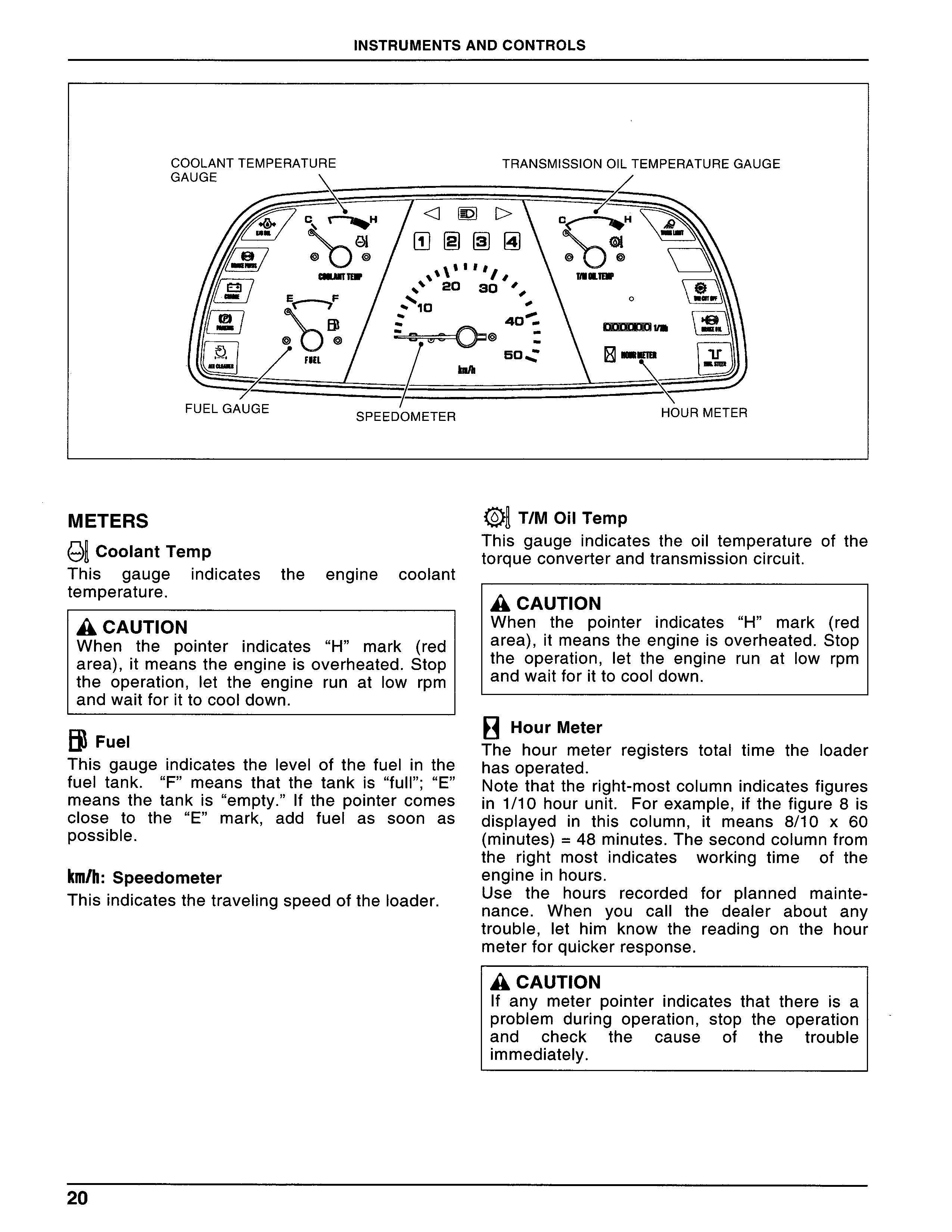
O且CoolantTemp
This gauge indicates the engine coolant temperature. a CAUTloN
When the pointerindicates“H”mark(red area),itmeanstheengine andwaitforittocooldown.
甜Fuel
This gaugeindicates thelevelof the fuelin the fueltank.“F”means that the tankis“ful]”;“E” means the tankis“empty.”lf the pointer comes C10Se tO the“E”mark,add fuelas soon as POSSible.
km/h:Speedometer
Thisindicatesthetrave=ngspeedofthe10ader.
朝T/MOilTemp
This gaugeindicates the oiltemperature of the torqueconverterandtransmissioncjrcuit. a CAUTloN
When the pointerindicates“H”mark(red area)・itmeanstheengine and waitforitto cooldown.
目HourMeter
The hour meter registers totaltjme theJoader hasoperated.
Notethatthe right-mOStCOlumnindicatesfigures inl/10hourunit.Forexamp[e,ifthefigure8is displayedin this column,it means 8/10 x 60 (minutes)=48minutes.Thesecondcolumnfrom the right most indicates working time of the englneinhours.
Use the hours recorded for planned mainte- nance. When you call the dealer about any troubIe,let him know the reading on the hour meterforquickerresponse. a CAUTloN lf any meter pointerindicates that thereis a PrObJem during operation,StOP the operation and check the cause of the trouble immediately.
STARTER SWlTCH
a WARNlNG
Beforetryingtostarttheenglne,makesure that the shift Leverisin neutral,Parking brakeis applied,and the]oad handling leverisIocked.For details,See the section TRAVELINGIaterin this manual.
A cAUT10N
Do not turn the starter for more than lO SeCOnds at a time,Wailuntilthe starter motor and engine come to a complete stop or about 30seconds before trying agaln,tO PrOteCtthe batteryandstartermotor.
AwARN[NG
Do not turn the starter switch off during traveling;Otherwise the e]ectric $yStem might be damaged or the loader might COme tO malfunction.
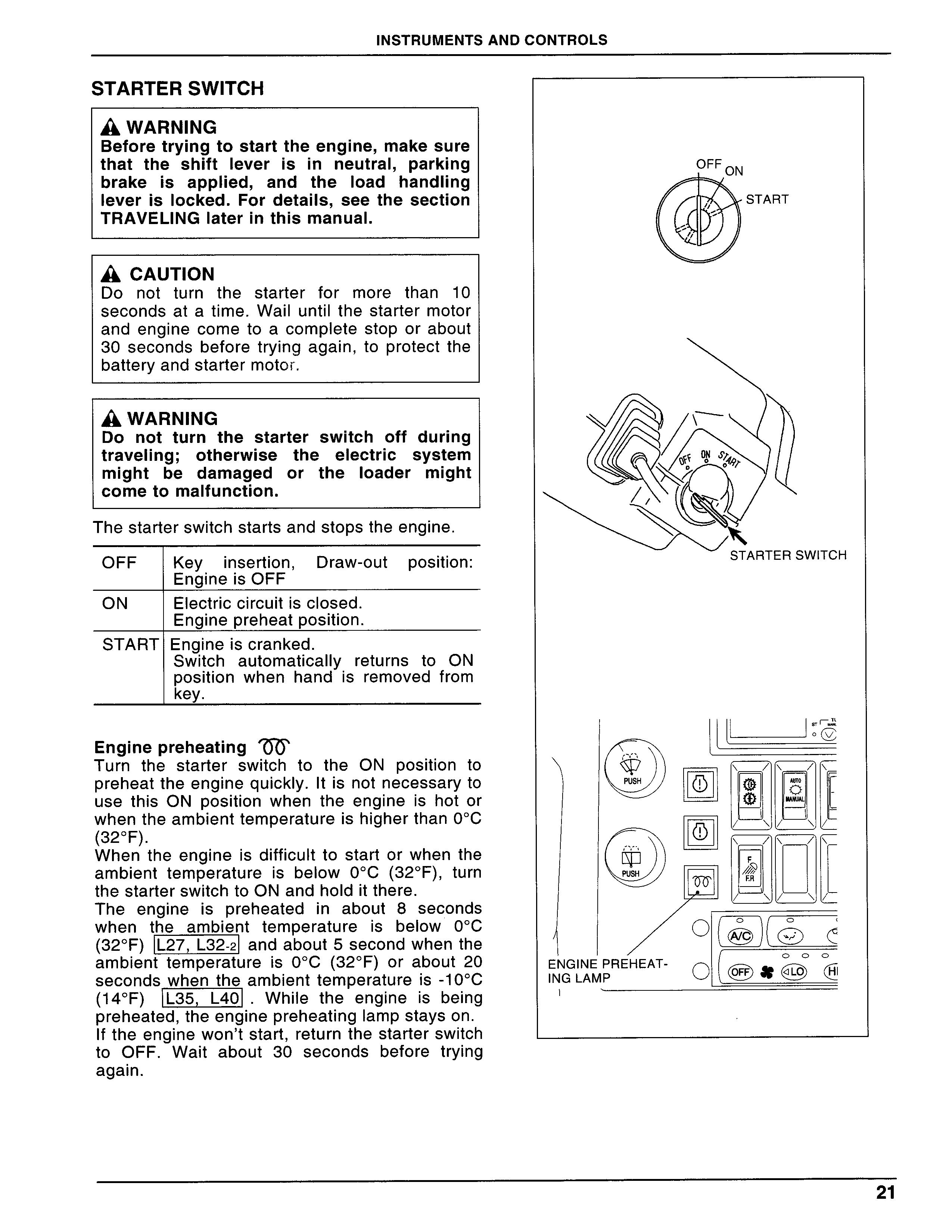
Thestarterswitchstartsandstopstheenglne.
OFF Keyinsertion,Draw-Out POSition: Engine is OFF ON ElectriccircuitiscLosed. Enginepreheatposition・
START Englneiscranked.
Switch automatica”y returns to ON POSitionwhenhandisremovedfrom key.
Enginepreheatingでひ
Turn the starter switch to the ON position to Preheattheeng[nequickly.1tisnotnecessaryto use this ON position when the engine is hot or WhentheambienttemperatureishigherthanOOC
(320F).
When the englneis difficultto start orwhen the ambient temperatureis below OOC(320F),turn the starterswitch toON and hoJditthere.
The englneis preheatedin about 8 seconds temperatureis below OOC
When the ambient and about5second when the (320F) L27,L32-2 ambient temperatureis OOC(320F)or about20 ambienttemperatureis-100C
.Wh‖e the eng[neis being SeCOnds when the (140F)
Preheated,theenglnePreheatingLampstayson・ lftheeng]neWOn’tstart,returnthestarterswitch to OFF.Wait about 30 seconds before try[ng agaln・
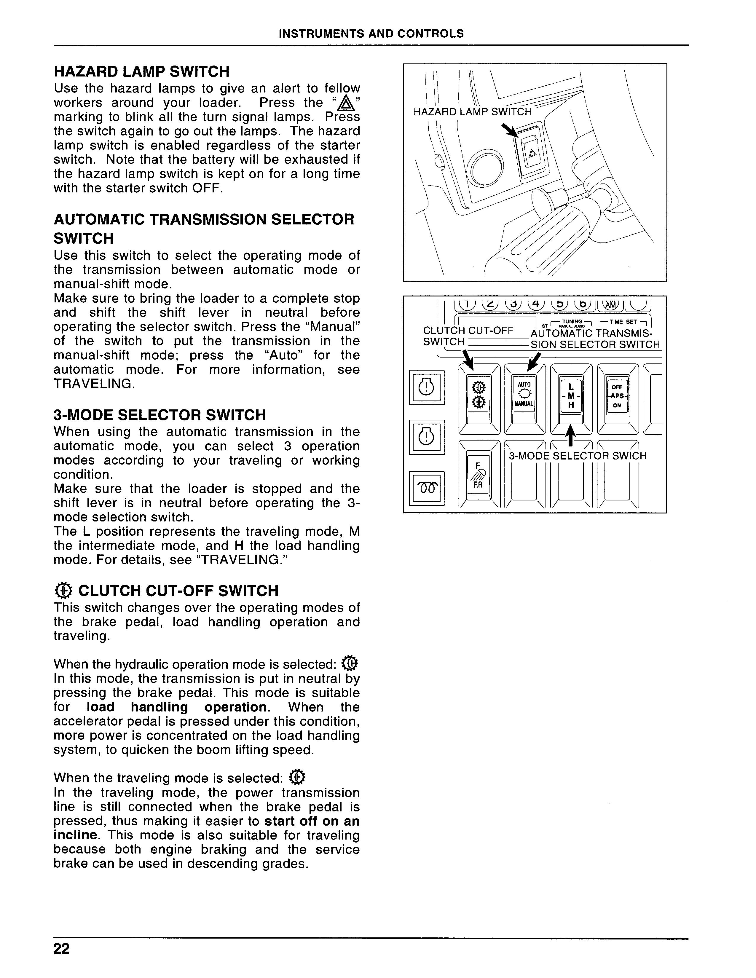
Hazardlampswitch
Use the hazard lamps to give an alert to fellow WOrkers around yourloader二 Press the“息” marking to blinkalltheturn slgnallamps.Press theswitchagaintogooutthelamps.Thehazard lamp switch is enabled regardless of the starter SWitch.NotethatthebatterywilJbeexhaustedif the hazardlampswitchiskeptonfora10ngtime With the starterswitch OFF.
AUTOMATlC TRANSMlSSlON SELECTOR SWITCH
Use this switch to select the operatjng mode of the transmission between automatic mode or manuaI-Shift mode,
Makesuretobringthe Loadertoacompletestop and shift the shift lever in neutral before OPeratingtheselectorswitch.Pressthe“Manual” of the switch to put the transmission in the manuaトshift mode;PreSS the“Auto”for the automatic mode.For moreinformation,See TRAVELING.
3-MODESELECTORSWITCH
When using the automatic transmission in the automatic mode,yOu Can SeLect 3 0Peration modes according to your traveling or working COndition.
Make sure that theloaderis stopped and the Shiftleverisin neutralbefore operating the3- mode seIection switch.
The L position represents the traveling mode,M theintermediate mode,and H the[oad handling mode.Fordetails,See“TRAVELING.”
尊CLUTCHCUT・OFFSWITCH
Thisswitchchangesovertheoperatingmodesof the brake peda[,10ad handling operation and travellng.
Whenthehydraulicoperチtiopm?deisselected=㊥ lnthismode,thetransmlSS[OnlSPutinneutralby PreSSlng the brake pedal.This modeis suitable for10ad handling operation.When the acceleratorpeda=spressedunderthiscondition, morepowerisconcentratedontheIoad handling SyStem,tOquickentheboom[iftingspeed.
WhenthetraYeIingmodeisseLected=O ln the travel-ng mOde,the power transmission lineis stiH connected when the brake peda]is PreSSed,thus making jteasiertostartoffonan incline. This mode is also suitable for traveling because both englne braking and the service brakecanbeusedindescendinggrades.
ノ戚woRKLIGHTSW[TCH
F: Presslng the“F”mark willturn the front WOrklightON.
F・R:Presslng the“F・R”mark willturn both the nr B=.p.essing.he
A cAUTION
Do notturnontheworklightwhentravelingon Publicroads.
LIGHTING SWITCH
DQ:=Widthandtai[lightscomeon・ ≡D:Width,tail,andheadlightscomeon. OFF:Alllightsgooutwhentheswitchisturned to neutra10rOFF.
PARKING BRAKE SW]TCH a WARNlNG
Presstheparking brake“ON”switch before leaving the10ader.Make sure the parking brake switchis turned OFF before$tarting the10ader.
Presstheparking brake“ON”switchtoapplythe Parking brake to theIoader.The monitorlamp COmeS On.The parking brake can also be used asanemergencybrake. a CAUTloN
Donotusetheparkingbraketoslowdownthe loader exceptin an emergency;Otherwiseit might cause premature wear of the parking brakeordamagetothebrakesystem.
Pressthe“OFF”partoftheswitchto reIeasethe Parkingbrake.
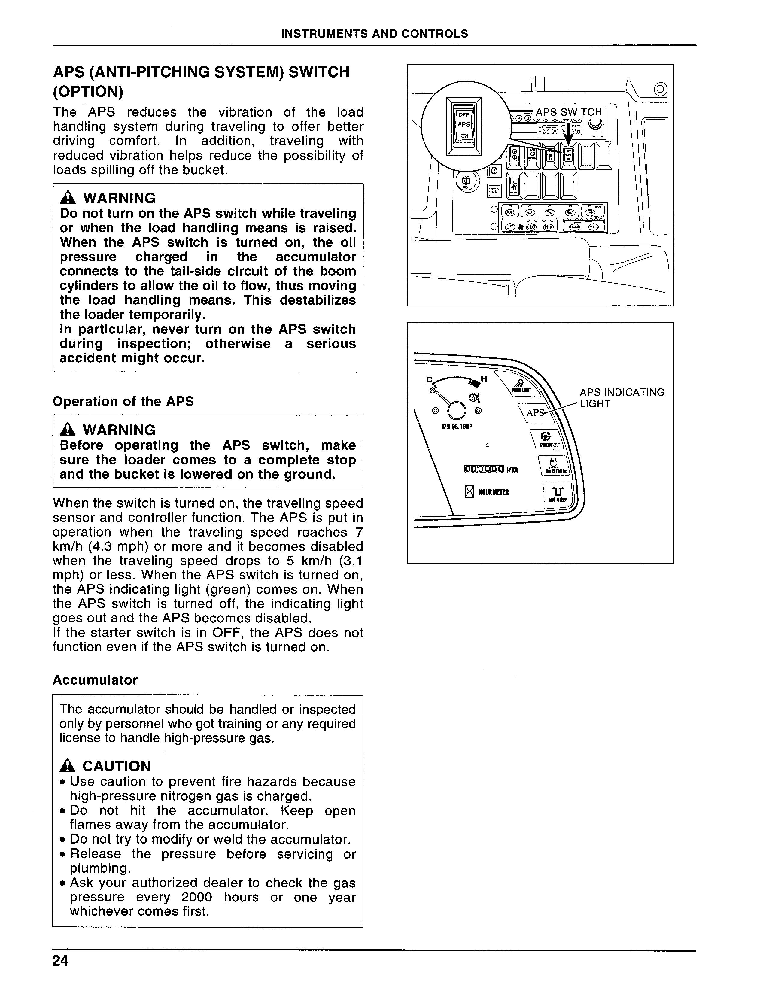
APS(ANTl-PITCHINGSYSTEM)SWITCH (OPT10N)
The APS reduces the vibration of the load handling system during traveling to offer better driving comfort.1n addition,traVeling with reduced vibration heLps reduce the possibility of loadsspj”ingoffthebucket.
A wARNING
DonotturnontheAPSswitchwhiletraveling Or When the10ad handling meansis raised.
When the APS swjtchis turned on,the oiJ PreSSure Charged in the COnneCtS tO the tail-Side circuit CyljnderstoaIIowtheoiltofJow, the10ad handling means.This theIoadertemporarjly. accumulator Of the boom thusmov]ng destabitizes ln particular,neVer turn On the duringinspection;Otherwise accidentmightoccur.
OperationoftheAPS A wARN州G
APS$Witch a Ser10uS
Before operating the APS switch,make $ure the10ader comes to a compJete stop andthebucketi$10Weredontheground.
Whentheswitchisturnedon,thetravelingspeed SenSOrandcontro‖erfunction.TheAPSisputin OPeration when the traveJing speed reaches 7 km/h(4.3mph)ormoreanditbecomesdisabled When the traveling speed drops to5km/h(3.1 mph)orless.When theAPSswitchisturnedon, theAPSindicatinglight(green)comeson.When the APS switchis turned off,theindicating[ight goesoutandtheAPSbecomesdisabled.
1f the starter switchisin OFF,the APS does not function eveniftheAPS switchisturned on.
AccumuLator
Theaccumulatorshould be handledorinspected
Onlybypersonnelwhogottrainingoranyrequired Iicensetohandlehigh-PreSSuregaS.
A cAUT10N
●Use caution to prevent fire hazards because high-PreSSurenitrogengasischarged.
・Do not hjt the accumulator.Keep open f[amesawayfromtheaccumulator.
・Donottrytomodifyorweldtheaccumulator.
・Release the pressure before serviclng Or Plumbing.
●Askyourauthorized dealerto checkthe gas
PreSSure eVery 2000 hours or one year
Whichevercomes first.
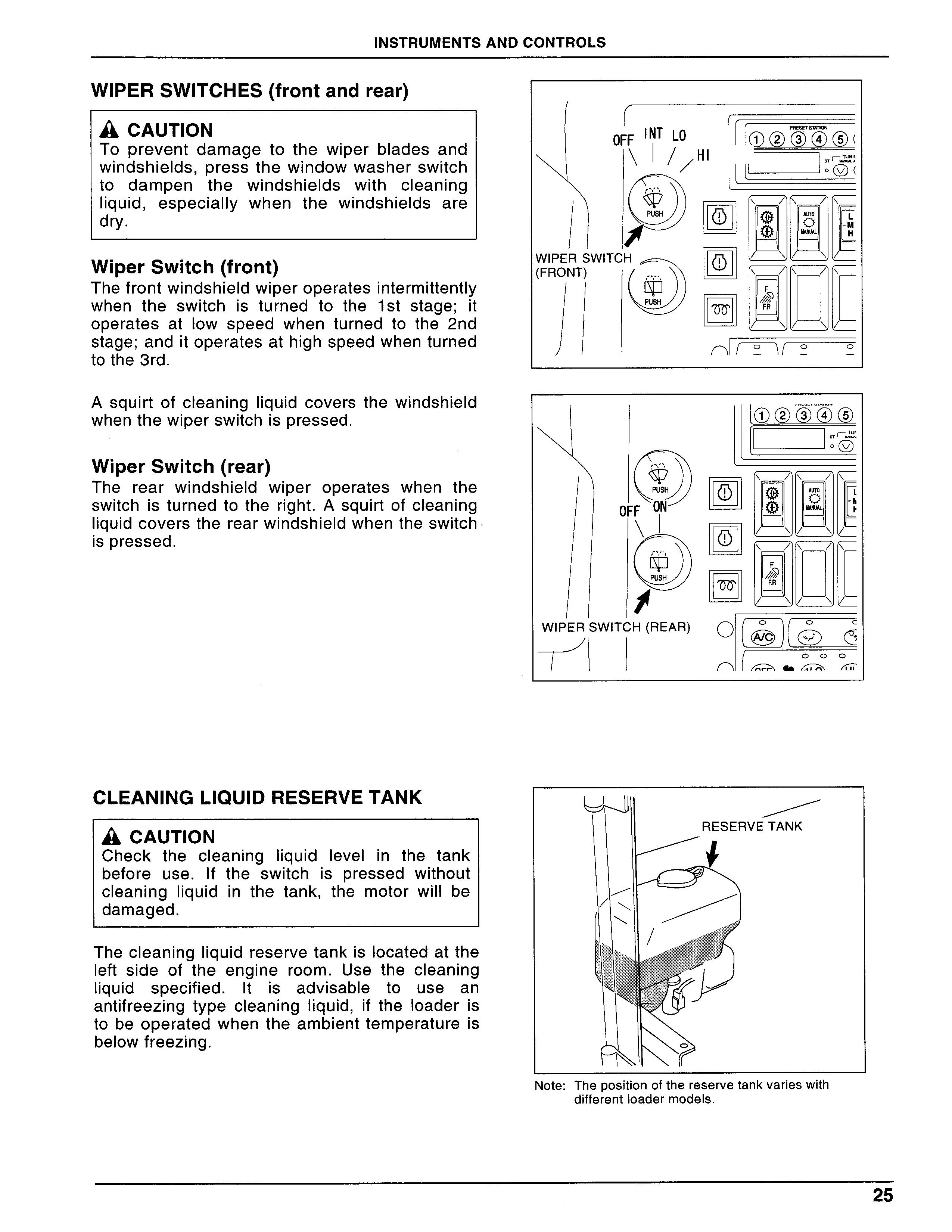
WIPERSWITCHES(frontandrear)
A cAUT[ON
To prevent damage to the wIPer blades and Windshields,PreSS thewindowwasherswitch to dampen the windshields with cIeaning liquid,eSPeCiaIly when the windshields are dry.
WiperSwitch(front)
ThefrontwindshieLdwIPerOPerateSintermittently When the switchis turned to thelst stage;it operates at low speed when turned to the 2nd Stage;anditoperatesathighspeedwhenturned to the3rd.
A squirt of c[eanlngliquid covers the windshield WhenthewIPerSWitchispressed.
WiperSwitch(rear)
The rear windshield wIPer OPerateS When the SWitchis turned tothe right.Asquirt ofcleanlng liquidcoversthe rearwindshieldwhentheswitch ispressed.
Cleaning Liquidreservetank
A cAUT10N
Check the clean[ngliquidlevelin the tank before use.1f the switchis pressed without CleaninglIquidin the tank,the motor wi]lbe damaged.
Thecleanlngliquid reservetankis10Catedatthe left side of the engIne rOOm.Use the cLeanlng Liquid specified.]tis advisable to use an antifreezlng tyPe Cleanlngliquid,if the10aderis to be operatedwhen theambienttemperatureis beIowfreezlng.
Note:Thepositionofthereservetankvarieswith different10adermodeLs.
SHIFT LEVER
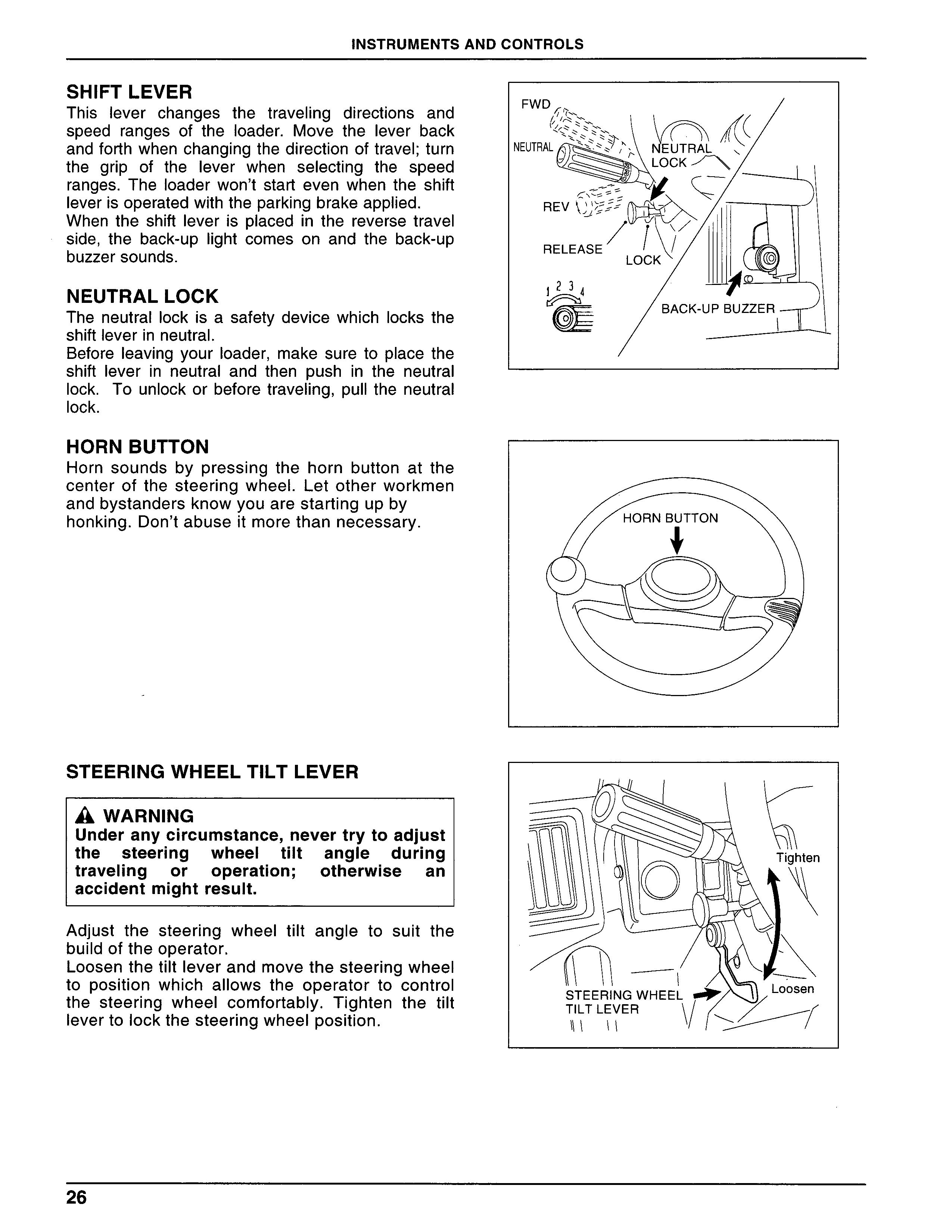
Thislever changes the travel[ng directions and SPeed ranges of the10ader.Move thelever back andfo代hwhenchanglngthedirectionoftravel;turn the grip of the lever when selecting the speed ranges.Theloaderwon’t start even when the shift leverisoperatedwiththeparkingbrakeapplied.
When the shiftleveris placedin the reverse travel Side,the back-uPlight comes on and the back-uP buzzersounds.
NEUTRALLOCK
The neutrallockisa safetydevicewhichJocksthe Shiftleverin neutraI.
BeforeleavJngyOur10ader,make sure toplacethe Shiftleverin neutraland then pushin the neutra. lock.To unJockorbeforetraveling,Pullthe neutral 10Ck.
HORN BUTTON
Horn sounds by presslng the horn button at the CenterOfthe steerlng Wheel.Letotherworkmen andbystandersknowyouarestartingupby honking.Don’tabuseitmorethannecessary,
STEERINGWHEELT]LT LEVER
a WARNlNG
Underanycircum$tanCe,neVertrytOadju$t the steerlng Whee[tilt angle during traveling or operation; Otherwise an accidentmightresuJt.
Adjust the steer[ng Wheeltilt angle to suit the buildoftheoperator.
LoosenthetiltleverandmovethesteerlngWheeL to position which al10WS the operator to control the steerlng WheelcomfortabJy.Tighten the tiJt levertolockthesteerlngWhee[position.
TURNSIGNALLEVER(W/D]MMER SWITCH)
Usethislevertoindicate theturnlng direction of the10ader.When theleveris placedin a turn POSition,theturnslgnallightb‖nks.ByLiftingthe lever,the headIightswilldim.When theIeveris OPerated,the corresponding monitorlamp a[so COmeS On, Don’t failto return thislever to neutraLaftermakingaturn.
BRAKEPEDALS(RIGHTANDLEFTPED- ALSINTERLOCKED)
A wARNING
・When descending on anincLine,S10Wdown the10ader by uslng both the brake pedal and englne braking.Using the brake pedal too often might lead to insufficient oil PreSSure,thus makingit difficuIt to brake the10ader.
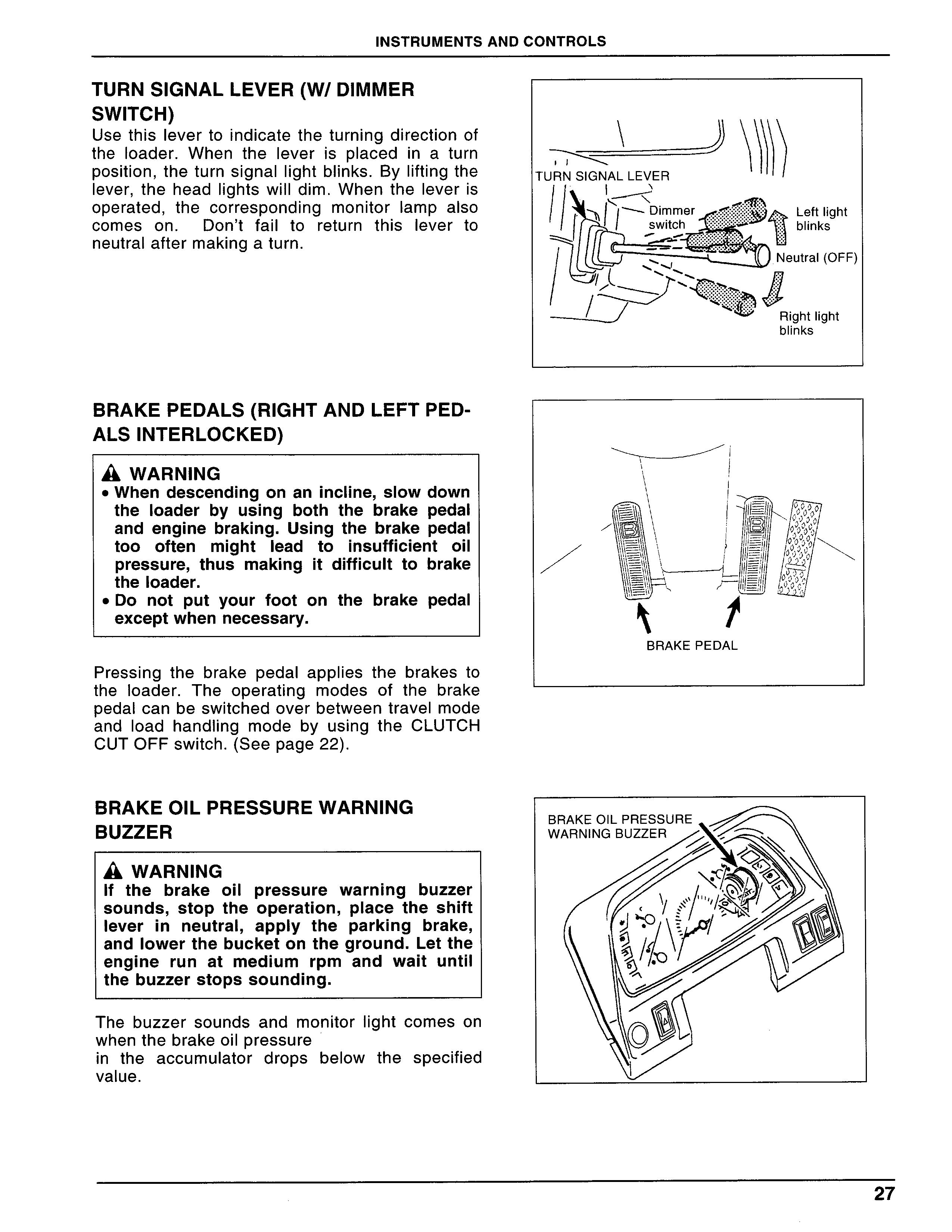
・Do not put your foot on the brake pedal exceptwhennecessary.
Pressing the brake pedal applies the brakes to theloader.The operating modes of the brake Pedalcanbeswitchedoverbetweentravelmode and10ad hand=ng mode by uslng the CLUTCH CUTOFFswitch.(Seepage22).
BRAKEOILPRESSUREWARNLNG BUZZER
A wARNING lf the brake oiL pre$Sure Warning buzzer $Ounds,StOP the operation,Place the shift leverin neutra[,aPPly the parking brake, and10Werthebucketontheground.Letthe englne run at medium rpm and wait untjl thebuzzerstopssounding.
The buzzer sounds and monitor]ight comes on Whenthebrakeoilpressure in the accumulator drops below the specified Value.
Accelerator Pedal
A cAUT10N
The further the pedalis pressed,the more englne SPeedincreases.However,do not PreSS the pedal more than necessary; Otherwiseit wilLincrease fuelconsumption,

CauSeShortlifeofthe englne andin theworst CaSelead to a serious accident.
Controls the traveling speed of the loader and WOrkingspeedofthe10adhandlingsystem.
Fuse
A wARNING
]fanyfuseis b10Wn,turn the starterswitch Off and check the cause and troubleshoot PrOPerly before replacing the fu$e With a newoneofthesamecapacity.
Fuses serve as a safety device for the electric SyStem,PreVenting excessive current from f10Wlng[n the circuit.The fuses have different CaPaCity depending on the circuits they serve. When replaclng them wjth new ones,uSe the SameCaPaCity.
The fuse boxis[ocated at the right side of the OPeratOr’sseat.Wheninspectionorreplacement is needed,remOVethescrewsecurlngthecover. Thefusesareofthe bladetype.Attheleft-Side frameinside the englne rOOm are tWO SLow-b10W fuses(100A)withafusiblelinkwire(green).
The L35 and L40 have four line fuses for the englneCOntrOlunitbythebladefuses.
A Before trying to check the fuses,make $ure the starter switchis turned off and the POWeri$Off.Checking should be carried outin the order of the bIade fuses,S10W b[ow fuses, and fusiblelinkwire.
Forwhatcircuiteachfuseservesfor,refertothe labelinsidethefuse boxcover.
OPERATOR,SSEAT A wARN州G
Adjusttheoperator’sseattoapositionwhich PrOVides easy acce$S tO allhand and foot COntr01s.
Do not ti]t the backrest too far back,eVenif thebackrestisadjustabLe.
A wARN州G
Lf the10aderis equlPPed with a seat belt, Checkthe be[tfordamageor100SemOunting bolts.A[waysweartheseat beltafterseating yourselfin the operator’s$eat.Too slack a Seatbeltwi”notbeeffectiveenoughto keep the operator safely secure.Adjust the tightnessoftheseatbeltproperly.
SLlDE SEAT LEVER
Adjust the seat position by moving the lever towardyou.
SUSPENSIN ADJUSTMENT HANDLE
Turn the handle knob to adjust the seat SuSPenSion according to the operator’s prefer- enCe.
SEAT HElGHT ADJUSTMENT LEVER
Seatyourselfintheoperator’sseat,mOVethelever to the right or]eft,and adjust the seat height accordingtotheindividualoperator’sphysique・ Usuallysettheseatheighttotheright-endorthe SeCOnd from the right-end marking・ The suspension stroke will be automatically adjusted according to the setting of the seat height adjustmentlever.
RECLINING SEAT ADJUSTING LEVER
Adjust the angle of the backrest・Do not tjIt the backrest too far back.The armrestis a rotationaL type・
Note:The backre$t has a strong reaction. When adjusting the backre$t angle, holdthe]everwithyourhandorbody.
ARMREST
Thearmrestisarotationaltype.Youcanchange theangLeofthearmrestbyturnlngthedialatthe backofthe armrest.
SEAT BELT
Beforeweanngtheseatbelt,adjusttheseatbeLt length.Too slack seat beltis not effective enough to keep the operator safely secured・ Adjustthetightnessoftheseatbe]tproperly・ lnsert the buckleinto the tank untilit cIicks.To unlock,PuShtheredbutton.
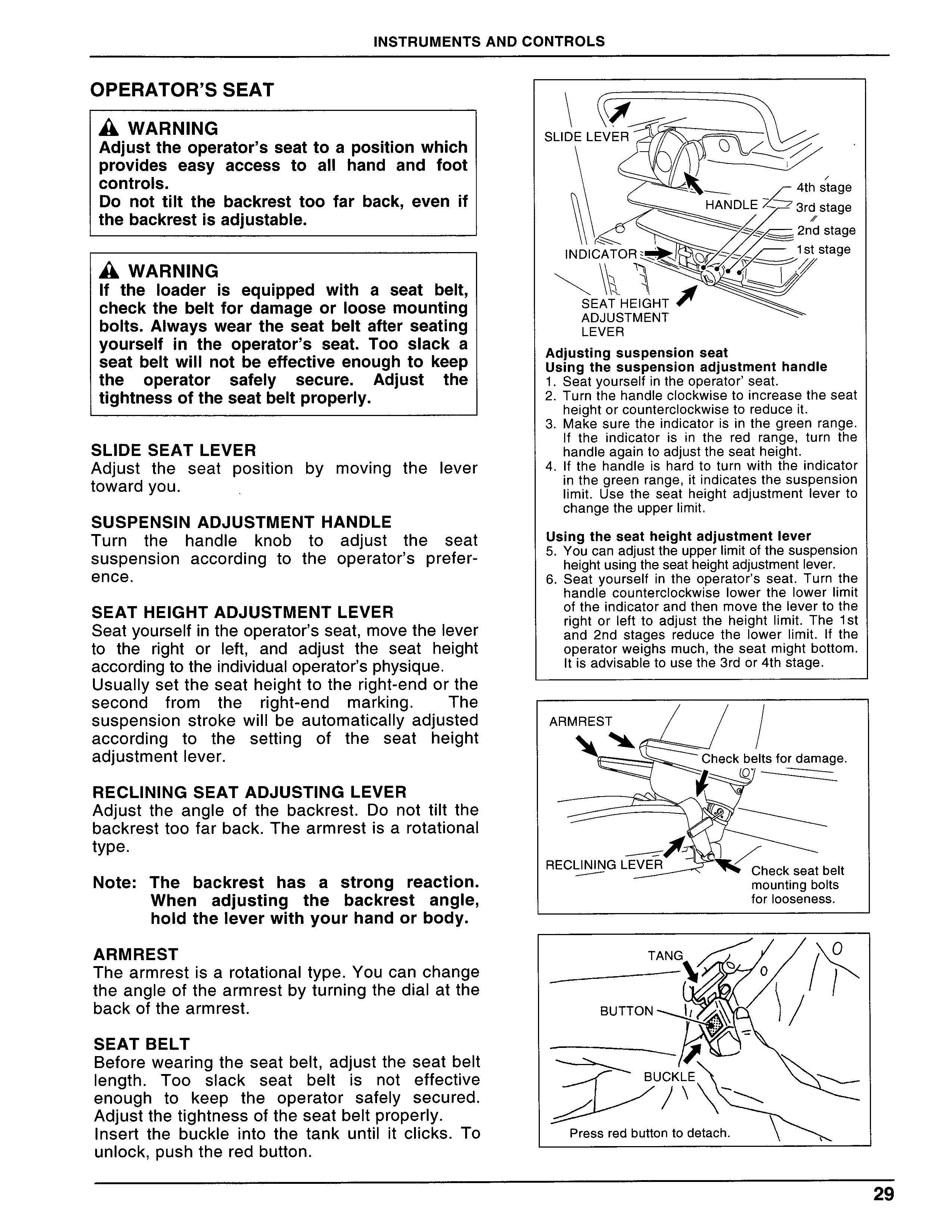
Adjusting$uSPenSion seat U$ingthesu$PenSionadju$tmenthandle l.Seatyourselfintheoperator’seat・
2.Turn the handle c10Ckwisetoincreasetheseat heightorcounterc10Ckwisetoreduceit・
3.Makesuretheindicatorisinthegreen rangeL lf theindicatorisin the red range,turn the handleagalntOadjusttheseatheight・
4.1f the handleis hard to turn with theindicator inthegreenrange,itindicatesthesuspension limit.Use the seat height adjustmentleverto Changetheupperlimit・
Usingtheseatheightadju$tmentlever
5.Youcanadjusttheupperlimitofthesuspension heightusingtheseatheightadjustmentlever・
6.Seatyourselfintheoperator’s seat・Turn the handle counterc10Ckwise10Wer the10Werlimit oftheindicatorand then move thelevertothe rightorleftto adjustthe heightlimit・Thelst and2nd stages reduce the10Werlimit・lf the OPeratOrWeighsmuch,theseatmightbottom, ltisadvisabLetousethe3rdor4thstage.
LOAD HANDL暮NG LEVER
A wARNING
・The10ad handIing lever shou[d be COntrOlled by hand whenyou are properly Seated.NeverattempttocontroIthelever unlessyouareproperlyseated.
・Beforeleaving the10ader,10Ck the Load handlinglever securely with thelever 10Ck.
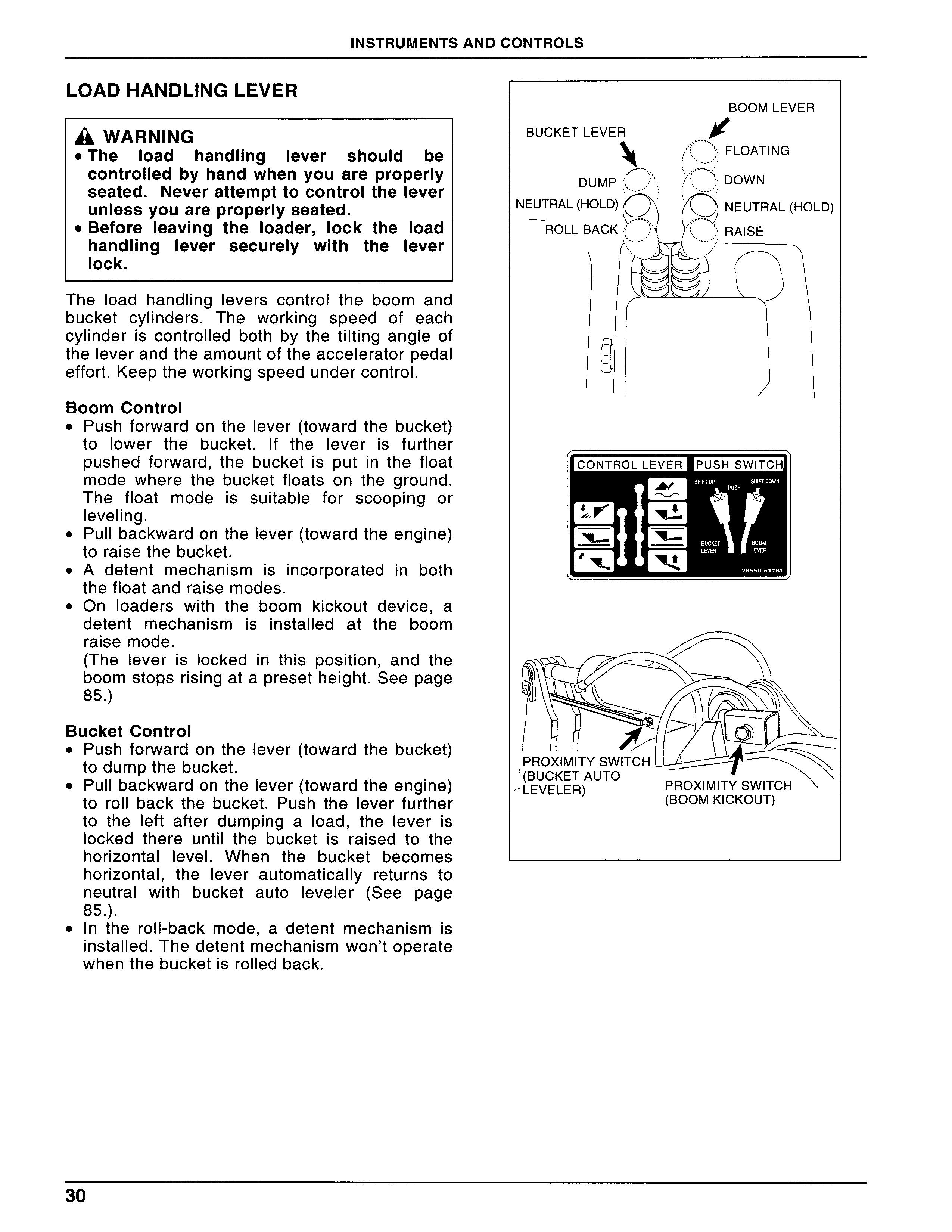
TheIoad handlinglevers controlthe boom and bucket cy=nders.The working speed of each Cylinderis contro[led both by the tilting angle of theleverandtheamountoftheacceleratorpedaI effort.KeeptheworkingspeedundercontroL.
Boom Control
・Push forward on thelever(toward the bucket) to10Wer the bucket.1f theleveris further PuShed forward,the bucketis putin the f10at mode where the bucket fIoats on the ground, The float mode is suitable for scooping or levelLng.
・Pu”backwardonthelever(towardtheengine) to raise the bucket.
・A detent mechanismisincorporatedin both thef10atand raise modes.
・On10aders with the boom kickout device,a detent mechanism is installed at the boom raise mode.
(TheleverisIockedin this position,and the boomstopsrislngataPreSetheight.Seepage 85.)
Bucket Contro[
・Push forward on thelever(toward the bucket) todumpthebucket.
・Pullbackwardonthelever(towardtheengine) to ro”back the bucket.Push thelever further to the Left after dumplng a10ad,theleveris locked there until the bucket is raised to the horizontallevel.When the bucket becomes horizontal,thelever automatical[y returns to neutralwith bucket autoIeveIer(See page 85.).
●ln the roll-back mode,a detent mechanismis insta]led.Thedetentmechanismwon’toperate When the bucketis rolled back.
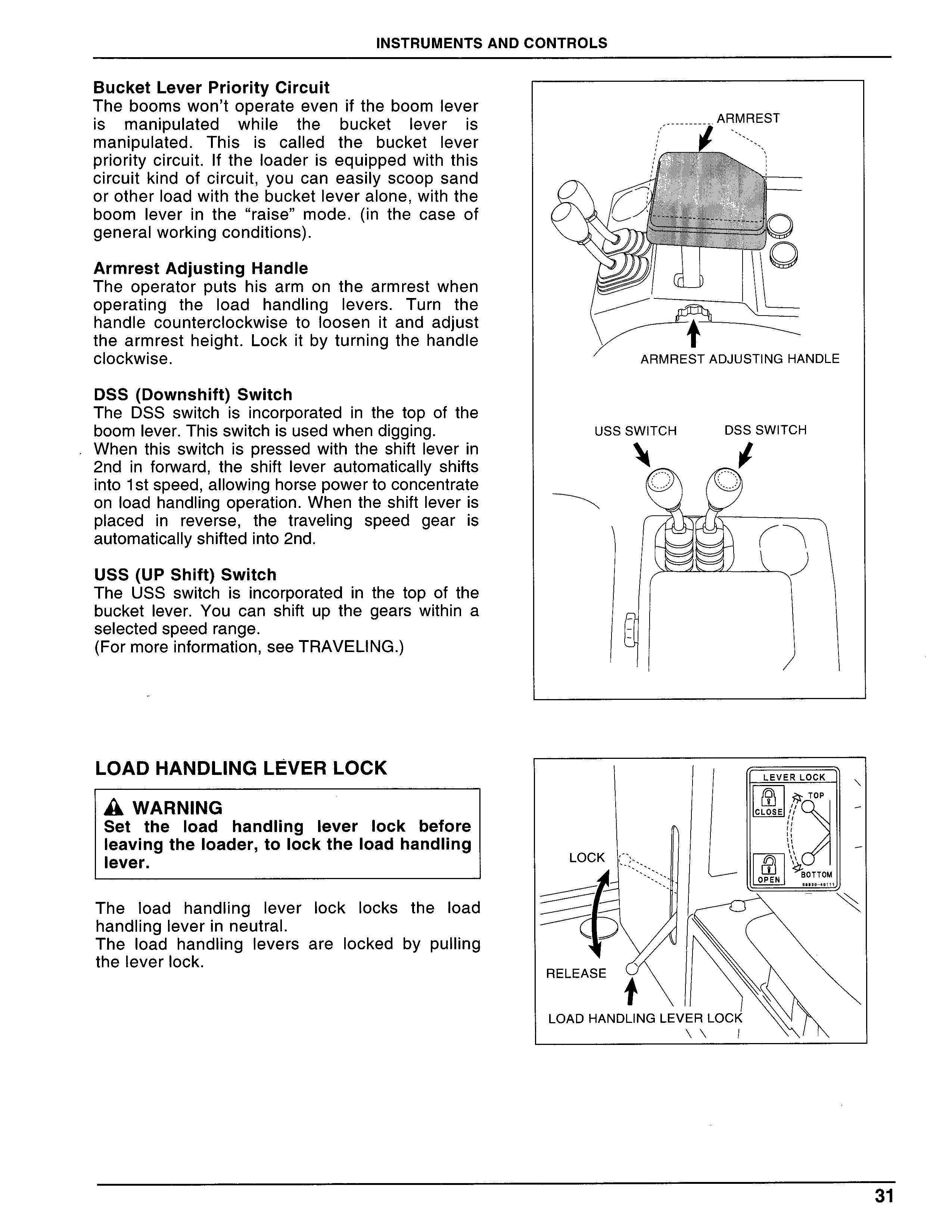
BucketLeverPriorityCircuit
Theboomswon’toperateeveniftheboomlever is manlPulated while the bucketleveris manlPulated.Thisis calLed the bucketlever Pr10ritycircuit.1ftheloaderis equlPPedwith this Circuit kind ofcircuit,yOu Can eaSilyscoop sand
OrOther10adwiththebucket[everalone,Withthe boomleverin the“raise”mode.(in the case of generalworkingconditions).
Armrest Adjusting Handle
The operator puts his arm on the armrest when OPerating theload handlinglevers.Turn the handle counterc10Ckwise toloosenit and adjust the armrest height.Lockit byturnlngthe handle Clockwise.
DSS(Downshift)Switch
The DSS switchisincorporatedin the top of the boomlever.Thisswitchisusedwhendigglng.
When this switchis pressed with theshiftleverin 2ndin forward,the shiftlever automatically shifts intoIstspeed,a”owInghorsepowertoconcentrate OnloadhandIingoperation.Whentheshiftleveris
Placedin reverse,the traveling speed gearis automatica”yshiftedinto2nd.
USS(UPShift)Switch
The USS switchisincorporatedin the top of the bucketlever.You can shift up the gears within a Selectedspeedrange. (Formoreinformation,SeeTRAVEuNG.)
LOADHANDuNGLEvERLOCK
a WARNlNG
Set the10ad handlinglever10Ck before leavingthe10ader,tO10Ckthe10adhandJing lever.
The10ad handlingleverlock Locks the10ad handlingleverinneutraL.
The10ad handlinglevers arelocked by pulling the Lever10Ck.
Safety Link
A wARNING
The$afetylinkconnectsand10Cksthefront frame and the rear frame.Useit when SerVicing or storjng the10ader.Remember toattachtheβclip.
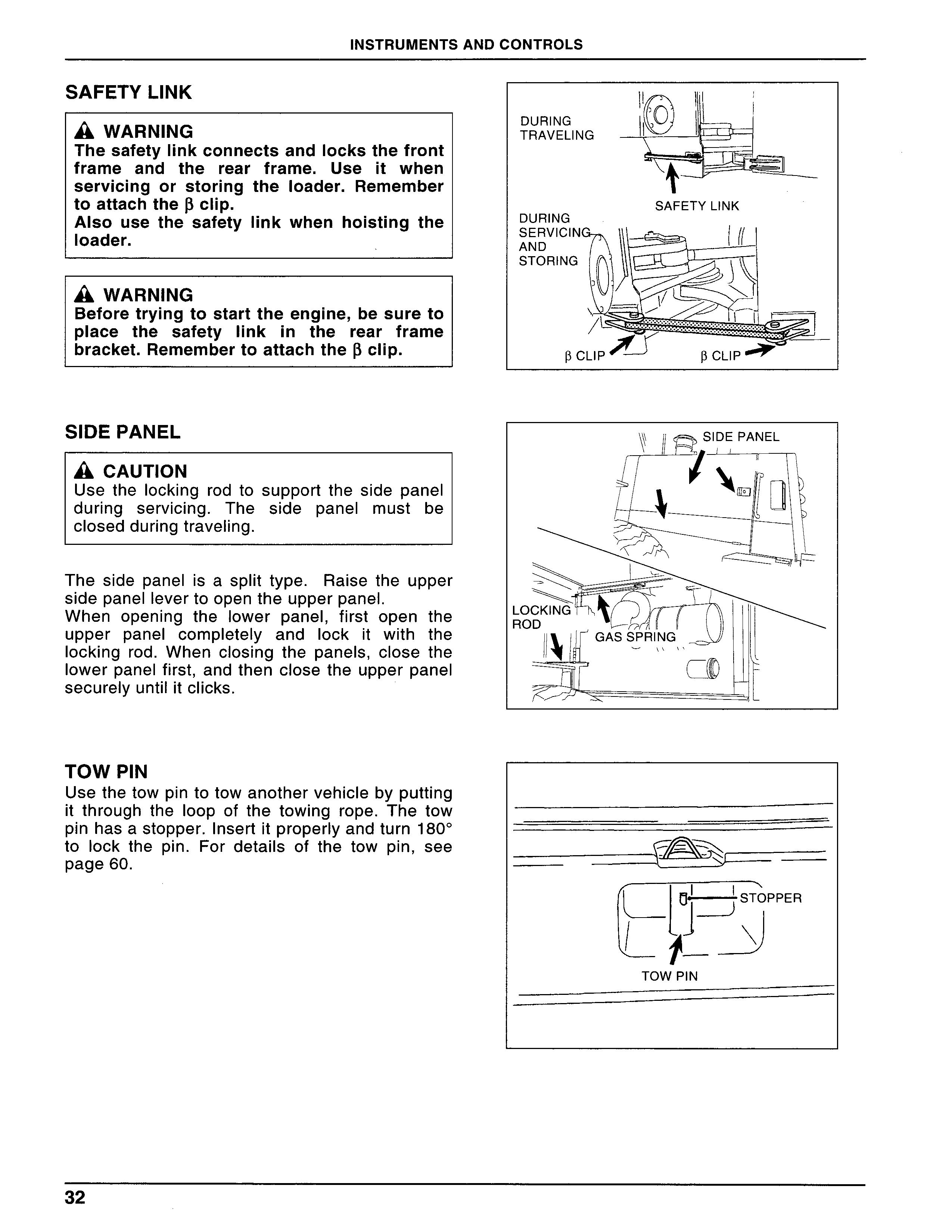
Also use the safety link when hoisting the 10ader.
A wARNING
Beforetryingtostarttheenglne,besureto
Place the safetylinkin the rear frame bracket.Remembertoattachtheβclip.
Side Panel
A cAUTlON
Use the locking rod to support the side panel during serviclng.The side panelmust be CIosedduringtrave[ing.
The side panelis a split type.Raise the upper Sidepanellevertoopentheupperpanel.
When openlng theJower panel,fjrst open the upper panelcompleteLy and10Ck jt with the locking rod.When c10S[ng the panels,CLose the lowerpanelfirst,andthen closethe upperpaneI SeCurelyunti[itclicks.
Tow Pin
Usethetowpintotowanothervehiclebyputting it through theloop of the towlng rOPe.The tow Pinhasastopper.lnsertitproper[yandturn1800 to[ock the pln.For details of the tow pln,See Page60.
S.DEVIEWMIRROR
A wARNING
When driving back,do not count on the Sideview mirrors too much.Use them as SuPPlementalmeans,100kingdirectlyinthe directionyouaregoingtobackisbe$t.
Adjustthesideviewmirrorstogainfullrearview Whenyouareseatedintheoperator’sseat.
LADDER
A wARNtNG
U$e the recommended hand holds and StePS With atlea$t three point$Of support When getting on and off the10ader; OtherwiseyoumightsJiporfall.

Twoladders areinstal[ed,One On eaCh side of the10ader.
1tis advisab[e to use the(eft-Sideladder, because getting on and off with the right-Side ladder might be a=ttle restricted by the Load handlinglever.
BUCKET
A bucket with flat reversible cutting edge is StandardequlPment.
We have a wide range of buckets and attachments to meet your specific job requlre- ments.Contactyourauthorizeddealer.
VANDALlSM PROTECTlON
Hydraulic oiltank cover,tranSmission oilcap, and battery cover can be keylocked or bolted・ Thefueltankcapandsidepanelscan beJocked Withthestarterkey.
ROPSCAB,AIRCONDIT]ONER,ANDRAD10
ROPS CAB
Standard equipment
AIRCOND[T10NER
Standard equlPment.Formoreinformation,See Page39.
RAD10
Standard equlPment.Formoreinformation,See Page42.
OPENlNG AND CLOSlNG DOORS
A wARNING
Usecautjon nottogetyourfingercaughtin the door.Thereis a fear of your finger beingcaughtifyou putyourfingerbetween the]ever and the knob when holding the doorlever.
AcAU旧N
Afterclosmgthedoor,makesureitissecurely Closed.
When openlng the door from outside,grlP the doorleverto unIockthe stopper.When opemng the doorfrominside,Pu‖the doorlevertowards theinsidetounlcokthestopper.
DOOR LOCK
A cAUT10N
After10Ckingthedoorwiththedoorlock,make Sureitissecurelylocked.
Theleftdoorislockedfrom outside by uslngthe key and the right doorislocked frominside by PuShingdowntheknob.
REGULATOR HANDLE
The door window can be rolled up and down by turnlngthehandLe.
ROOM LAMP
A roomlampIS equ[PPed on the ceiling of the Cab.YoucanturntheLamponandoffbyshifting the switch.With the switchin neutraI,theIamp turnsonandoff,interlockedwiththeoperationof the door.Thelamp turns on when the dooris OPened.
Remembertoturn offthelampbeforeleavjng the10ader.
ROOM MIRROR
Alarge room mirroris equlPPedinside the cab, Adjustitto galn fullrearview beforestartingthe loade「.
TRAY,CUPHOLDER
A cAUT10N
ThetraylSnOtaWater-PrOOftype, Donotspi”fluidoverit.
You can ho[d a bottle with a capln the cup holder.
ASHTRAY
A wARNING
Takeduecaretopreventfirehazards.
An ashtray is equlPPed for a smoker’s COnVenlenCe.
CfGARETTE LIGHTER
A wARNING
Do not touch areas other than the knob. Youcouldgetyourfinger$burnt.
Use tolight cigarettes.Pushin the knob.When the=ghteris hot enough to[ight a clgarette,it POPSOut.
COOLANDHOTBOX(L40)
You can keep beverages in this box where the COO10r hot air js sent from the air conditioner. Make sure bottles you are going to put in are SeCurelycappedorplugged.
AIRCONDITJONERSYSTEM CONFIGURAT10N
Mode switches and discharge OPenlng$
Note:
・Thenumbersinthesketchshowthedischarge OPenlngS・
・On L27and L32-2,the condenserislocatedon topofthehydrau[icoilcooler;OnL35andL40, itis Locatedin front of the cooLing fan.The receiver is located to the transmission at the rightsideoftheenglnerOOm.
A[R CONDIT10NER
A wARNING
●Use caution not to expose your body to COld air directly.You might bein bad Shape.Get comfortabJe air direction and VOlume by adjusting the10uVer Of the di$Chargeopening$.
●lf the air conditioneris u$ed for a10ng Period of time with the windows cIosed, OPenthewindowsfromtjmetotime.
A cAUT10N
●Warm up the englne Sufficiently pnor to OPeratingtheairconditionerswitch.
●ltis good practicetoventi[atethe operator’s COmPartment before cooJingif the tempera- tureinsidethecompartmentistoohigh.
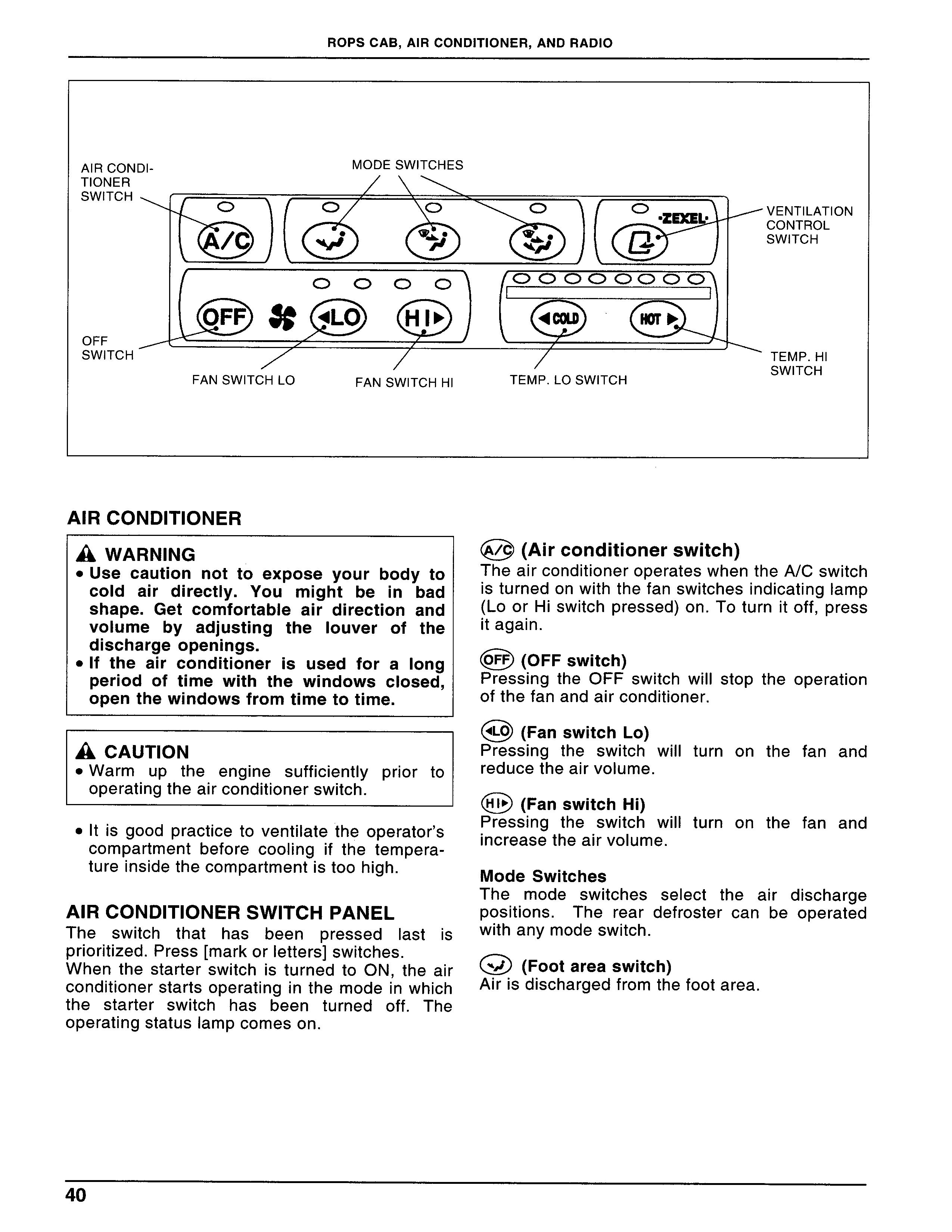
Aircondit10nerswitch Panel
The switch that has been pressed[astis Prioritized.Press[markorletters]switches. When the starterswitchis turned to ON,the air COnditionerstartsoperatinglnthemodeinwhich the starter switch has been turned off.The OPeratingstatuslampcomeson.
⑲(Airconditioner$Witch)
TheairconditioneroperateswhentheA/Cswitch isturnedonwiththefanswitchesindicating[amp (LoorHiswitchpressed)on.Toturnitoff,PreSS itagaln.
Pressing the OFF switch will stop the operation Ofthefan and airconditioner.
Pressing the switch will turn on the fan and reducetheajrvolume.
㊥(FanswitchHi)
Press暮ng the switch wil[turn on the fan and increasetheairvolume.
Mode Switches
The mode switches seJect the air discharge POSitions・The rear defroster can be operated Withanymodeswjtch.
(⊇)(Footareaswitch)
Airisdischargedfromthefootarea.
(撃(Defroster/faceswitch)
Air[S discharged from both the windshield area and the monitor/meter panel’s right andleft OPen]ngS.The airdirection can be adjustedwith theopenlng’s10uVerS.
㊨(Footarea/defroster/faceswitch)
Airisdischargedfroma‖airdischargeopenlngS・
㊥(Temp・LosTjtch)
The temperaturelSloweredin steps for every depression ofthe switch.The4indicatinglamps at the left side are used as a rough guide of COOling temperature;the4indicatinglamps at therightsideareforh占ating.
㊤(Temp・HisTit?h)
The temperaturelSlnCreaSedin steps forevery depressionoftheswitch.
(宣)(VentilatiopcontroIswitch)
AIRCONDIT10NEROPERATING PROCE- DURE
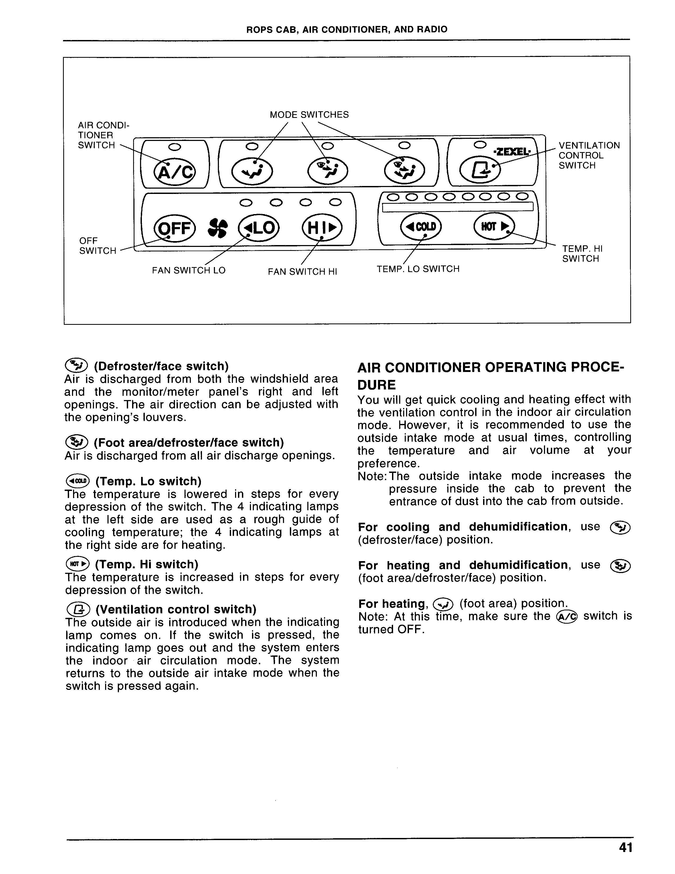
Youwillgetquickcoolingandheatingeffectwith the ventilation controlin theindooraircircuLation mode,However,itis recommended to use the OutSideintake mode at usualtimes,COntrOHing the temperature and air volume at your Preference,
Note:The outsideintake modeincreases the PreSSureinside the cab to prevent the entrance ofdustintothecabfrom outside.
For coo[ing and dehumidification,uSe㊧ (defroster/face)position・
For heating and dehumidification,uSe(箪) (footarea/defroster/face)position・
Forheating,(⊇)(footarea)position・ Note:Atthistime,makesurethe⑲switchis turned OFF.
Theoutside alr[Sintroducedwhen theindicating lamp comes on.1f the switchis pressed,the indicating lamp goes out and the system enters theindoor air circulation mode.The system returns to the outside air intake mode when the SWitchispressedagaln.
Rad10
To receive broadcasting clearly,eXtend the antenna.
① PowerOnNoLumeBalanceSwitch
TheradioisturnedONbypresslngtheswitch.The SOund volumeisincreased byturnlngitclockwise anddecreasedbyturnlngitcounterc10Ckwise.The radioisturnedoffbypresslngtheswitchagaln.
Pullthe switch to controlthe balance between the rightandleftspeakers.
②ToneControIAdjustmentKnob
The treble is enhanced by turning the control C10Ckwiseandthebasepartisenhancedbyturnlng itcounterc10Ckwise.
O Display Control Button
When the radio is turned on with the starter SWitchin the ON position,the djsplay shows a radio frequency.You can switch the display to thetimeofdaybypresslngthisbutton.
④ BandSelectorButton
Push the button to switch over the bands between FM andAM.
(9 Station PresetButtons
Press oneofthe sixbuttonstotuneintothestation youwant,fromamongthestationsprogrammedin memory.The disp[ay shows the frequency of the Station.
⑥
Lcd
When the radio is turned on with the starter SWitchin the ON position,the display shows a radio frequency.When the Display ControI Button③ispressed,thedisplayshowsthetime Ofdayfor5seconds andthen returnsto a radio frequency.When the radiois turned off,the displayalwaysshowsthetimeofday.
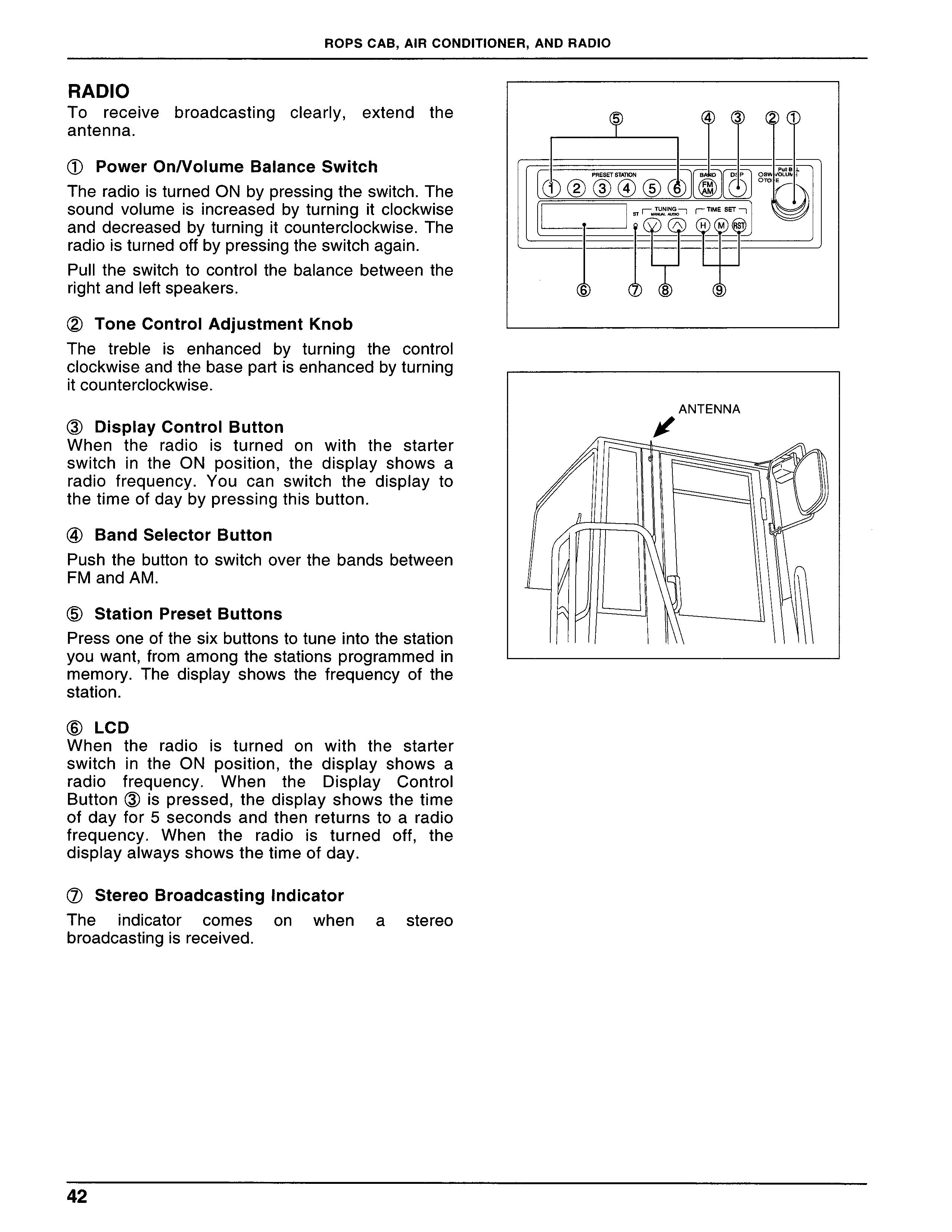
⑦ StereoBroadca$tingIndicator
The indicator comes on when a stereo broadcastinglSreCeived,
⑧TuningButtoncQ),㊦Automatictuning lfthebuttonispressedandheldformorethanO,5 SeC,theradiobeg[nStOSearChforastationtoward the high frequency direction.1t tunesin the first Station which can be most heard.1f one of the6 Stationpresetbuttonsispressedformorethanl.5 SeCOnds,the stationis programmedinto memory.
Using the same manner,yOu Can PreSet uP tO6 radiostationsinmemory.
ManuaL Station Select
The radio searches for a station toward the low frequency direction when◎buttonis pressed; andtoTardthehighfrequencydirectionwhen㊦ buttonlS PreSSed.The stations are selectedin StePS foreverydepression ofthe button forless than O.5seconds.Holding down the buttons for morethan O.5seconds,the stations are seLected in succession.For the procedure for presetting Stations,uSe the same manner as describedin
“Auto Station Select.”
⑨TimeAdjustmentButton
Usethe⑪toチdjusttheunitofhours;the㊥f?r the unit of mlnuteS.The numbers advance]n StePSforeverydepressionofthebutton]essthan
O.5 seconds. The numbers advance in succession when the button is pressed and held for morethan O.5seconds.
The unit of hours advances as foLlows:1,2,3, ...12,1,2.The unit of minutes advances as fol]ows:00,01,02,...59,00,01.1t does not increasethedigit.
㊥is usedforresettingthec10Ck・Pressthe buttonto resetthetime toOO min.00sec.
●00-05 min:The c10Ck returns to OO min.00
SeC.
●55-59min:The c]ock advances one hour and thedisplayreturnstoOOmin,00sec・
●06-54min:Thec10Ckis not reset.