2 minute read
5.2 Lifting machine


TOOLS
ITEM CABLE (A) CABLE (B) SPREADER BARS (C)
SIZE Ø25 X 13.6 m Ø25 X 13.7 m 3.67 m Q'TY 1 1 2
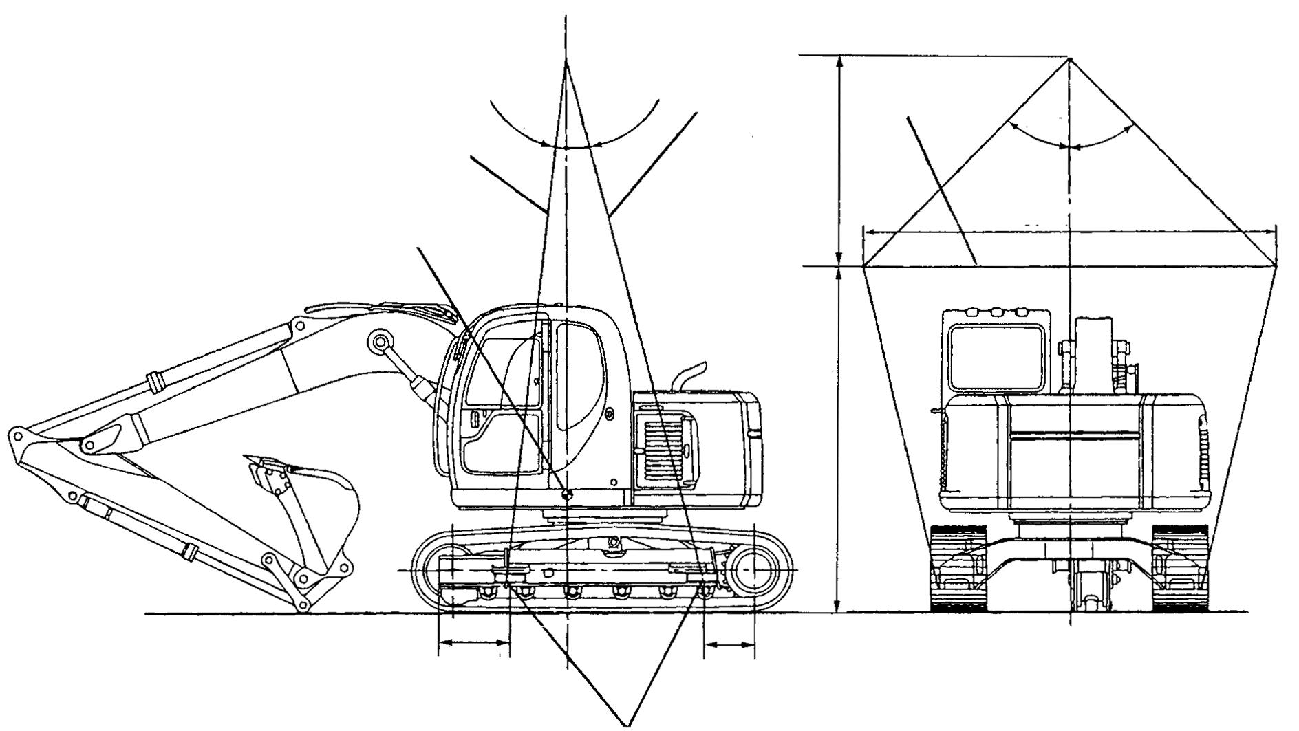
WEIGHT: 11,900 kg (26,230 lbs) ARM: 2.2 m (7’-3”) SHOE: 600 mm (23,6”) MODEL: E115SR
(A)
(7° ) (10 °) (B)
CENTER OF GRAVITY
1900 mm (6´-3˝)
3100 mm (10´-2˝)
(C)
(44°)(44°)
3670 mm (12˝)
632 mm (24.9˝)
NOTE: Lifting machine with wider track shoes will tend to shift the Center of Gravity slightly forward, toward the center of the slewing ring.
5.2LIFTING MACHINE
The following procedures are for lifting the machine, as built by your Dealer. These procedures do not take into account modifications made to the machine that affect machine weight or center of gravity. 1. Locate lifting locations at the front and rear of each crawler frame. 2. Attach cables or wire rope with a capacity rating sufficient to lift the machine, at lifting locations.
CAUTION
Place a hardwood or steel block between cables and crawler frame to prevent damage to the tracks from cables during lifting.
3. Bring loose ends of cables together at machine center of gravity and attach to an overhead lifting device with a rated lifting capacity sufficient to lift the machine.
NOTE:
It may be necessary to place reinforced spreader bars between lifting cables to prevent damage to the machine during lifting. 4. Slowly lift and move machine to desired location.
WARNING
Always use proper lifting equipment and devices. Use of improper lifting equipment could allow the load to shift or fall causing severe damage, serious injury or death.
WARNING
Do not use counterweight lifting eyes to lift whole machine. Lifting eyes can fall under this load resulting in personal injury. Refer to operators manual for proper way of lifting machine.
586 mm (23˝)
PLACE BLOCK BETWEEN EACH CABLE AND FRAME
F16438gb
WARNING
Do not use the counterweight lifting eyes to lift machine.
WEIGHT: 14500 kg (31,973 lbs) ARM: 2.2 m (7’-3”) SHOE: 800 mm (31.5”) MODEL: E115SRL
CENTER OF GRAVITY
TOOLS
ITEM SIZE Q.TY CABLE (A) Ø 28 X 13,6 m 1 CABLE (B) Ø 28 X 13,6 m 1 SPREADER BARS (C) 4.2 m 2
(A) (B)
(8.3˚) (10.8˚) 2,100mm (6´-11˝) (C)
(45˚) (45˚)
4,200mm (13´-9˝)
3,100mm (10´-2˝)
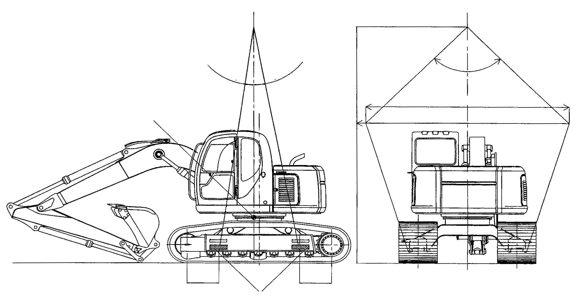
660mm (26.0˝)
NOTE: Lifting machine with wider track shoes will tend to shift the Center of Gravity slightly forward, toward the center of the slewing ring.
660mm (26.0˝)
PLACE BLOCK BETWEEN EACH CABLE AND FRAME
WARNING
Do not use the counterweight lifting eyes to lift machine.