3 minute read
9.5 Releasing swing brake


9.5 RELEASING SWING BRAKE
WARNING
Make certain that the attachment is on the ground to help prevent sudden rotation of the upper structure before attempting to release the swing brake. Refer to section X “LOWERING ATTACHMENT WHEN SUDDEN ENGINE FAILURE OCCURS”.
A.TOOLS & EQUIPMENT REQUIRED
1. Handtools required for removal of hydraulic tubes, hoses and fittings 2. Plugs and caps for tubes, hoses and fittings 3. 14 mm allen wrench 4. 6 mm allen wrench 5. Overhead lifting device capable of lifting and holding 45 kg (100 lb) 6. Plenty of clean, dry shop rags 7. Torque wrenches
B.PROCEDURES
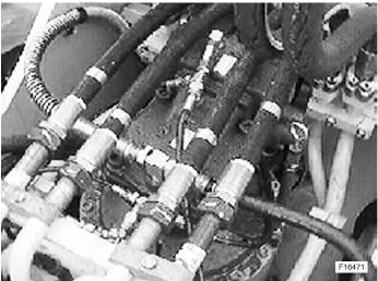
1. Lower attachment to ground. Refer to previous page for proper procedures in lowering the attachment. 2. Remove all hoses and tubes from the swing motor top plate and swing valve to gain access to the top plate mounting bolts. 3. Install the proper plugs and caps onto hoses, tubes and fittings to avoid the possibility of contamination entering the hydraulic system.
CAUTION
Use only plugs and caps designed to properly seal the specific hose, tube or fitting they are to be installed on.
4. Thoroughly clean the top of the slewing motor and slewing valve removing all dirt and debris.
NOTE: Place a large quantity of clean, dry shop rags around the swing motor to help catch any overflow of hydraulic oil from the removal of the top plate.
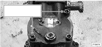
5. Loosen the four top plate attaching bolts with the 14 mm allen wrench.
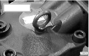
INSTALL PROPER CAPS AND PLUGS ON HOSES, TUBES AND FITTINGS TO HELP PREVENT CONTAMINATION ENTERING THE SYSTEM
F16305
M12-1.75X20mm LIFTING EYE
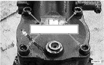
LOOSEN FOUR TOP PLATE ATTACHING BOLTS
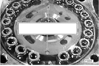
REMOVE TWO BOLTS, OPPOSITE CORNERS OF EACH OTHER
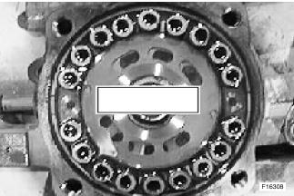
REMOVE ALL SPRINGS
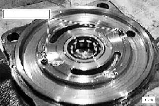
ALIGN DISTRIBUTOR PLATE HOLES TOWARDS FRONT AND REAR OF HOUSING
DOWEL PINS
6. Remove two top plate mounting bolts from corners opposite of each other. 7. Attach overhead lifting device to the lifting eyes and remove most of the slack from the cable or chain. 8. Carefully remove the remaining two bolts from the top mounting plate.
NOTE: The top plate will raise from spring pressure as the last two bolts are removed. Some movement of the upper frame may be experienced as the spring tension is released.
9. Using the overhead lifting device, carefully lift the swing motor top cover with swing shockless valve assembly and away from the swing motor.
CAUTION
Do not allow any dirt or debris to enter the swing motor or settle on the top plate.
10. Carefully remove all brake springs and place in a container filled with fresh, clean hydraulic oil. Then, seal the container to prevent contamination. 11. Align the holes of the distributor plate in the swing motor until they are located toward the front and back of the swing motor housing. 12. Carefully place the top plate over the swing motor and align the dowel pins of the top plate with the holes in the distributor plate. 13. Carefully and slowly lower the top plate into position on the swing motor and install, by hand, the four top plate mounting bolts. 14. Carefully and slowly lower the top plate into position on the slewing motor and install, by hand, the four top plate attaching bolts.
CAUTION
Make certain the top plate dowel pins and the distributor plate holes mesh together.
COPYRIGHT BY NEW HOLLAND KOBELCO CONSTRUCTION MACHINERY S.p.A. Strada di Settimo, 323 - 10099 S. MAURO T.SE ( TO ) ITALY
Reproduction of text or illustrations, in whole or in part, is strictly prohibited
Print No. 604.21.538.00 - 02 - 2005