31 minute read
Chapter 5


Indicators And Controls
Guards And Shields
Caution
Become familiar with and know how to use ALLsafety devices and controls on the Telehandler BEFORE operating it. Know how to stop the machine operation BEFORE operating it. This Mustang machine is designed and intended to be used ONLYwith a Mustang Manufacturing Company attachment tool, or a Mustang Manufacturing Company approved accessory or referral attachment tool. The Mustang Manufacturing Company cannot be responsible for product safety if the machine is used with an unapproved attachment tool.
Whenever possible and without affecting machine operation, guards and shields are used to protect potentially hazardous areas. In many places, decals are also provided to warn of potential hazards and to display special operating procedures.
Warning
Read and thoroughly understand all safety decals on the Telehandler BEFORE operating it. DO NOT operate the machine unless all factory-installed guards and shields are properly secured in place.
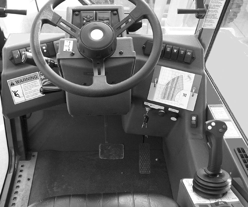
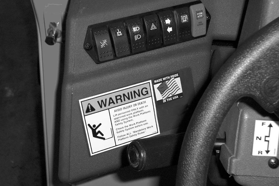
Dash Area
Keyswitch and Start Pushbutton
Keyswitch OFF: When the key is vertical in the keyswitch, power from the battery is disconnected to the control and instrument panel electrical circuits. This is the only position in which the key can be inserted or removed.
Keyswitch ON: When the key is turned one position clockwise from the vertical (OFF) position, power from the battery is supplied to to the engine and all control and instrument panel electrical circuits.
NOTE: If the engine requires repeated attempts to start, the key MUST be returned to the OFF position between starting attempts to prevent battery run down.
Start Pushbutton: With keyswitch in the ON position, press the start button to activate the starter. Release it as soon as the engine starts.
Temperature Control Knob
This knob is used to adjust the temperature inside the cab when the heater or air conditioner is in use.
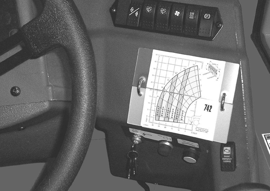
Load Zone Charts
Aseries of flip charts show lift height and reach limits relative to the load weight being handled with various attachment tools.
Right Bank Switches
Switches have graphic symbols to indicate function and effect. The following mode descriptions start with the first switch on the left.
Cold Starting Option: This switch activates the injection of an ether agent for faster engine start in cold weather.
Clutch Cutout: When activated, this switch allows faster engine acceleration and power to the hydraulics system without power to the drive axles while the service brake pedal is depressed.
In the OFF position, the clutch mechanism in the transmission remains engaged when applying the brakes. In the ON position, the clutch mechanism is disengaged while applying the brakes.
NOTE: Normal brake force will hold the machine in position while accelerating the engine to power the hydraulic control functions during load placement.
Wiper/Washer: Wiper motors and wash mechanisms on the windshield and top of the operator’s station can be activated with this switch, to maintain proper visibility for the operator.
Fan Speed: This switch increases and decreases circulation of heated or cooled air throughout the operator’s station interior.
Heater/AC: This switch turns on and off either heating or cooling selection for the operator’s station interior. (Units without air conditioning have only the heater mode switch.)
Parking Brake: When the machine is shut off, this switch should be depressed to activate the park brake mechanism in the front axle.
Engine Fault Shutdown Override Switch: This switch is located to the far right of the dash, below the load zone charts. Pressing the shutdown override switch will override an engine shutdown signal.
NOTE: Only machines equipped with the engine shutdown protection have this switch.
This switch must be pressed within 30 seconds to prevent undesired shutdown of engine. The switch can be overridden for 30 seconds at a time to move the machine to a safe location and to lower the boom to the ground. If the engine shuts down, the ignition switch must be turned off and then back on before the engine can be restarted.
NOTE: Holding the switch continuously “ON” will not reset the 30-second timer.
ing selector mode must be changed.
Axle Align: Allows the operator to check for straight tracking of the rear wheels. When activated, a green lamp lights on the switch to indicate straight tracking.
Lights Option: Work lights can be added to the operator station and boom to provide illumination for forward travel and work operations.
Hazard: This switch can be activated to make the tail lights flash on and off if the machine is stalled or temporarily stopped in a traffic area on the road or jobsite.
Turn Signal Option: This switch is used to indicate the direction of a turn. Depress the right arrow for right turn, depress the left arrow for a left turn.
Left Bank Switches
Switches have graphic symbols to indicate function and effect. The following mode descriptions start with the first switch on the left.
SteerSelect: Use “2-wheel mode” for higher speed travel. Use “4-wheel mode” for making tighter turns, usually on jobsite. Use “crab mode” when a small amount of side shift is needed for picking or placing loads. Any mode can be used in forward or reverse travel.
NOTE: The rear wheels are not self-centering. Use the axle alignment switch to determine when the rear wheels are tracking straight. To obtain the proper steer function selected and better machine tracking, make sure all wheels are in a straight ahead position before changing the steer mode.
Any of the steering position modes can be used in forward or reverse travel. The operator should learn to anticipate changes in machine movement if the steer-
Beacon: When a beacon is installed on the machine, activating this switch will produce a strobe-light on and off flashing for working in conditions that may obscure view of the machine.
Work Platform: This switch is used to activate the Work Platform Safety System. It is a red switch located in the farthest right slot of the left side switch bank. When activated, an amber lamp lights on the switch.
NOTE: This lamp will flash on and off, indicating that the system is not fully functional, until the brakes are held on for three or more seconds.
Adjustable Console
Position Adjust: This console can be adjusted so the steering wheel is placed in one of six positions for operating comfort. Pull up the small black handle on the left side of the console and re-position the steering wheel. Release the handle to lock in place.
Steering: The power steering motor is designed to give effortless steering with no shock reaction from the axle wheels to the steering wheel. Turn the steering wheel to the right or left to turn the machine in the direction of wheel turn action.
Horn Button: With the keyswitch on, press the center of the steering wheel to activate the horn.
Indicators Panel - Left Side
Fuel Level Gauge: Shows the amount of fuel remaining in the fuel tank.
Hourmeter: Indicates the operating time of the machine and should be used for maintaining the maintenance log (p. 71).
Indicators Panel - Right Side
Engine Oil Pressure Lamp: This display is located in the upper left corner of the top panel. It indicates whether or not there is sufficient engine lubricating oil pressure. During normal operation, with the engine running, this lamp should be off. During starting and when the keyswitch is on and the engine is not running, this lamp will be on.
IMPORTANT: If this lamp comes on during normal operation with the engine running, STOPthe engine immediately. After allowing the oil to drain down for a few minutes, check the engine oil level. Maintain oil level at or near the FULLmark on the dipstick.
Coolant Temperature Lamp: This display is located in the upper right corner of the top panel. It indicates if the temperature of the engine coolant is too high.
IMPORTANT: If this lamp comes on during normal operation with the engine running, STOPthe engine as soon as possible and check the engine cooling system.
AlternatorLamp: This display is located in the lower left corner of the top panel. It indicates the condition of the electrical charging system. During normal operation, this lamp should be off. If the charge rate is too high or too low, this lamp will come on.
Low Fuel Lamp: This display is located in the lower right corner of the top panel. When it first comes on, there is approximately 2.5 gals. (9.5 L) of fuel remaining. The fuel tank should be filled at this time.
Hydraulic Oil FilterLamp: This display is located in the upper left corner of the bottom panel. If this lamp comes on, it indicates that the filter element should be checked for possible replacement.
AirCleanerRestriction Lamp: This display is located in the upper right corner of the bottom panel. If this lamp comes on, the air cleaner should be checked for a clogged inlet or filter element.
Transmission Oil Temperature Lamp: This display is located in the lower left corner of the bottom panel. It indicates whether the transmission oil is at the proper temperature. During normal operation this lamp should be off.
IMPORTANT: If the temperature lamp comes on during normal operation, a problem may exist in the transmission system. Stop the machine as soon as possible and investigate the cause of the problem!
AccumulatorCharge Lamp: This display is located in the lower right corner of the bottom panel. When the operating pressure is too low, this lamp will come on. Alow pressure indication requires recharging the accumulator.
Travel Lever
Located on the left side of the console, this lever is used to change travel direction (forward or reverse) and the speed of travel around the jobsite or on a road.
Travel Direction: The selector MUSTbe in “N” (NEUTRAL) position before the engine can be started.
Position “F” (FORWARD)
Position “N” (NEUTRAL)
Position “R” (REVERSE)
NOTE: Backup alarm automatically sounds with travel lever in Reverse.
IMPORTANT: Care should be taken when downshifting or reversing, because damage to the transmission can occur if shifting is forced or attempted at too high a speed. Allow engine speed to slow before down shifting or changing direction.
Speed Range: Twist counter-clockwise or clockwise to change the transmission speed between low and travel range.
Position “4” TRAVELRANGE
Position “3” UPPER RANGE
Position “2” MEDIUM RANGE
Position “1” LOWRANGE
RIGHT SIDE PANEL
These controls and indicators are used to position the frame, boom, and attachment. Graphic symbols on the side panel illustrate the control actions.
Warning
DO NOT level the frame with the boom raised or extended. Level the frame ONLYwhile stopped, with the boom fully retracted and the attachment raised just enough to clear the ground.
Frame Leveling Switch: This switch is located on the right side panel behind the boom control joystick. The machine may be tilted slowly 10o to the left or right to level the frame and boom in relation to the ground.
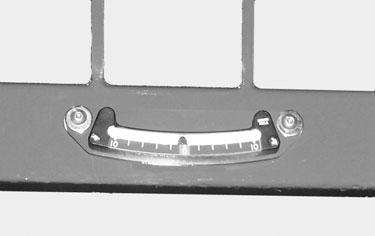
Frame Angle Indicator: Located in front of the operator on the ROPS upper cross tube. Position of the ball shows when the frame is level relative to a sloping ground surface.
Boom Joystick: This machine has a hydraulic-type boom with three or four telescopic sections. The sections extend by means of a hydraulic cylinder and chain system inside the boom, sequenced for uniform extension of each section.
The boom inner section nose has an attachment-carrying device. The Quick-attach is used for framing and masonry attachment tools. The Quick-attach II is used for special material handling attachment tools.
Both devices are “self-leveling,” meaning that when the operator tilts the attachment to a desired angle, that angle will be maintained as the boom is raised or lowered, extended or retracted, until a new angle is set.
The joystick handle is equipped with two yellow buttons and two blue buttons on the upper rear of the handle, and a trigger switch on the front of the handle. The yellow buttons operate the attachment tilt. The blue buttons operate the auxiliary hydraulics. The trigger switch controls the function speed of both the attachment tilt and auxiliary hydraulics.
To extend the boom, move the joystick right; to retract the boom, move the joystick left. To raise the boom, move the joystick rearward; to lower the boom, move the joystick forward.
To tilt the attachment tool up, press and hold the lower yellow button on the left side of the joystick handle, and pull on the trigger. To tilt the attachment tool down, press and hold the upper yellow button on the left side of the joystick handle while pulling on the trigger on the front side of the joystick handle.
To operate the auxiliary hydraulics, press and hold either the upper or lower blue button on the right side of the joystick handle while pulling on the trigger.
Pulling on the trigger increases the speed of the attachment tilt and auxiliary hydraulic functions.
NOTE: With the four-button joystick, the handle does not need to be moved to operate the tilt or auxiliary hydraulic functions.
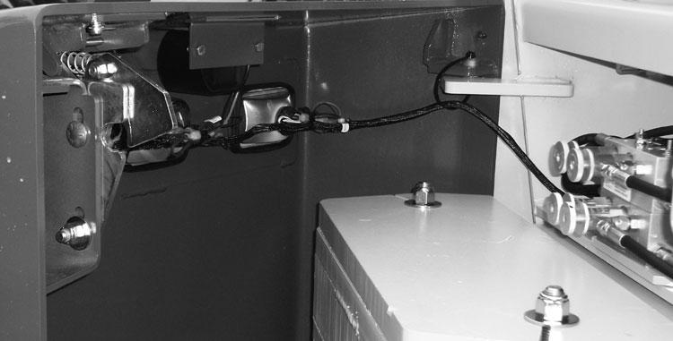
Speed Control Knobs: The four-button joystick handle also incorporates a manually-adjusted speed control to allow changing factory-set speeds. This speed adjustment is accomplished through the adjustment of the pilot pressure apply valves located in the rear compartment of the machine.
If the machine is equipped with auxiliary hydraulics, there will be two pilot pressure apply valves, each having two speed-control knobs. The upper pilot valve controls the auxiliary hydraulics, and the lower pilot valve controls the attachment tilt function. On the attachment tilt pilot valve, the left knob controls the attachment tilt-back speed, and the right knob controls the attachment tilt-forward speed. On the auxiliary hydraulic pilot valve, the function of the knobs will depend on the type of attachment used with the auxiliary hydraulics.
Turning a knob clockwise will increase the speed of its associated function. Turning a knob counter-clockwise will decrease the speed of its associated function.
NOTE: There is a locking knob located behind each adjusting knob, which must be loosened before the adjusting knob can be turned. After adjustment has been made, tighten the locking knob to maintain the selected speed.
AUXILIARY HYDRAULICS SPEED CONTROLKNOB
AUXILIARY HYDRAULICS SPEED CONTROLKNOB
AUXILIARYHYDRAULICS PILOTPRESSURE APPLY VALVE
LOCKING KNOB
L71378 DECAL
ATTACHMENTTILT BACK SPEED CONTROLKNOB
ATTACHMENTTILT FORWARD SPEED CONTROLKNOB
ATTACHMENTTILT PILOTPRESSURE APPLY VALVE
Warning
Use extreme caution when raising or extending the boom. The Telehandler MUST be level. Loaded or empty, the machine can tip over if it is not level.
ALWAYS place the transmission in neutral, apply the parking brake and keep the service brake pedal fully depressed before raising or extending the boom.
NEVER exceed the specified lift or reach capacities of the machine. Serious machine damage and personal injury may result. Refer to the load zone charts in the operator’s station or this manual.
If a boom circuit hose should break with the boom up, with or without a load, shut down the machine following the MANDATORY SAFETYSHUTDOWN PROCEDURE. DO NOT attempt repairs. Instead call your Gehl dealer for assistance.
The truss boom and winch attachment tools should ONLYbe used to lift and place loads when the machine is in a stationary position. DO NOT use to transport loads around the jobsite. This can cause the load to swing, resulting in either the load dropping or the machine tipping over.
NEVER use winch for lifting or moving personnel. NEVER exceed the maximum rated capacity of the winch (3000 lbs., 1360 kg) or exceed the load zone chart rating for winch applications.
DO NOT tilt the truss boom back more than 45o from horizontal. DO NOT attempt to use the rotating carriage as a load leveling function. Always level the frame prior to raising a load.
Failure to heed could result in death or serious injury.
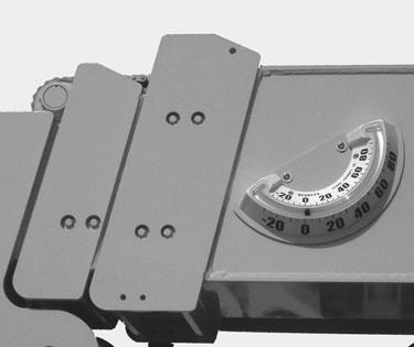
Boom Angle Indicator: Mounted on the left side of the outer boom, the position of the ball in the Boom Angle Indicator, shows the angle of the boom relative to the ground surface.
OutriggerOption Switches: This option is used to provide greater stability with specific applications. Depress the left switch forward to lower the left outrigger. Depress the right switch forward to lower the right outrigger. To raise the outriggers, depress both switches rearward.
Warning
Be sure NO persons or equipment are located where the outrigger pads will be positioned. DO NOT travel with the outriggers extended. Adequate clearance is required for the retracted outriggers when traveling through doorways or along narrow pathways.
DO NOT attempt to use the outriggers as a hydraulic jack for maintenance, or to level frame, or for other similar uses.
Failure to heed could result in death or serious injury.
Floor And Seat
Throttle Pedal: This pedal, operated by the right foot, controls the engine speed to match power requirements. Pushing down on the pedal increases the RPM, letting up on the pedal decreases RPM.
Service Brake Pedal: Pressing this pedal activates the internal braking mechanism on both wheels of the front axle.
Seat Positioning: The seat is mounted on rails for forward and rearward repositioning, for comfort and to accommodate the operator’s size. Aspring-loaded latch handle under the front of the seat actuates the adjustment mechanism.
Suspension Seat Option: This seat has a knob under the front of the seat to adjust the suspension. Turn the knob to the right for a softer ride, and to the left for a firmer ride.
Additionalindicators
The following indicators are for fluid level and pressures checks.
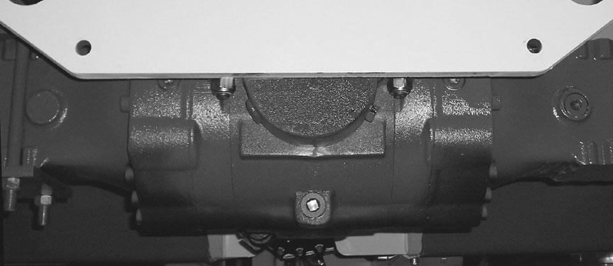
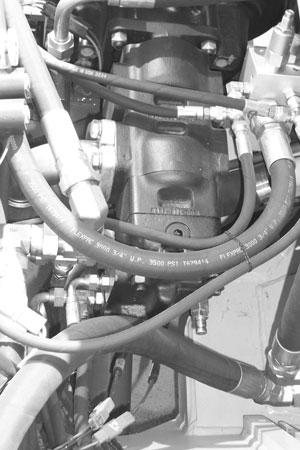
Hydraulic Test Port: Atest port located at the rear of the pump, for installing a test gauge to check hydraulic and steering system pressures.
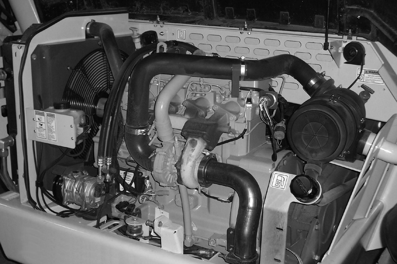
Coolant Level: The coolant can be checked and added through the radiator cap in the engine/power train compartment.
Service And Safetyfeatures
Backup Alarm: Located inside the rear frame cover, the backup alarm produces a loud warning sound whenever the transmission is in reverse.
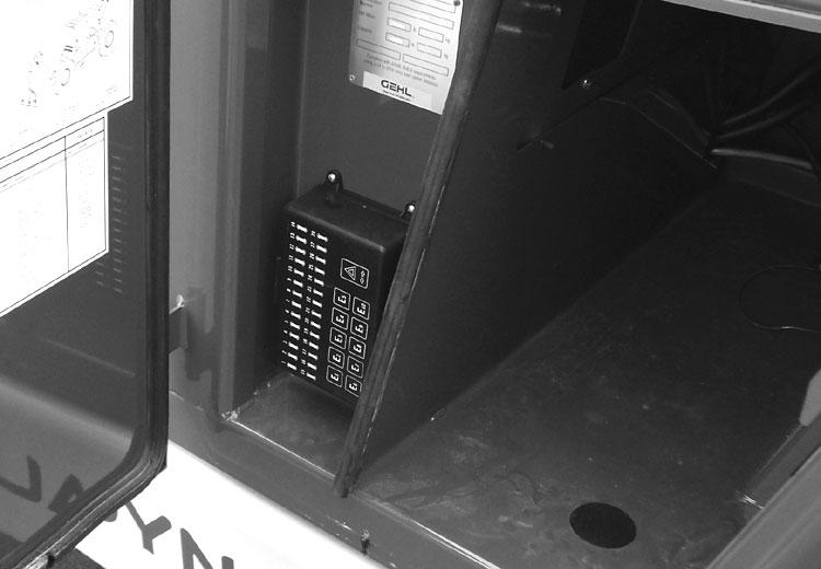
Fuse and Relay Box: This box is located on the front inside wall of the storage compartment behind the operator’s compartment. Adecal provides a quick reference guide for troubleshooting electrical functions.
Hydraulic ReservoirOil Level: The dipstick is located alongside the fill cap on the rear wall of the powertrain compartment.
Transmission Oil Level and Fill Cap: The combination dipstick/fill tube is located toward the front wall of the powertrain compartment.
Engine Oil Level: The dipstick is located on the right side of the engine.
Radiator Cap
Fuse/Relay Box
Side RearView Mirror: This mirror is located on top of the frame leveling cylinder mount. It provides the operator with a view of the area on the right side and behind the machine.
Battery Disconnect Switch: The battery can be disconnected from the electrical system by turning the switch key to the OFF position.
Locking Powertrain Covers: To tilt back the midframe access cover and the powertrain cover, pull out the lock mechanism handle and tilt up. Two gascharged springs help tilt back each cover, and keep them raised.
Attachment Tools
Mustang offers a versatile range of attachment tools to meet various lifting and material handling applications. Contact your Mustang dealer for specifications and ordering information.
Accessories
Mustang also offers a range of special accessories for this machine. Contact your Mustang dealer for specifications and ordering information.
NOTE: All accessories are field-installed unless otherwise noted. Information and parts for installing accessories are provided by your Mustang Telehandler dealer or Mustang Manufacturing Company.
Chapter 6
Operation And Adjustments
Generalinformation
Caution
BEFORE starting the engine and operating the Telehandler, review and comply with ALLsafety recommendations in the SAFETYchapter of this manual. Know how to STOPthe machine before starting it. Also, BE SURE to fasten and properly adjust the seatbelt.
ENGINE BREAK-IN
Your new engine does not require extensive “breakin.” However, for the first 100 hours of operation: Allow the engine to idle for a few minutes after every cold start, DO NOTidle the engine for long periods of time, DO NOToperate the engine at maximum power for long periods of time, and check the oil level frequently, and replenish as necessary with the oil specified in the engine manual.
John Deere engines use a “break-in” oil for the first 100 hours of operation. After the first 100 hours of operation, change the oil and replace the oil filter. Consult the Lubrication chapter or the engine manual for the type of oil to use in the engine. Refer to the Service and Storage chapter for the proper service intervals.
PRE-START INSPECTION
Every Pre-start Inspection must include more than checking the fuel and oil levels. It is the operator’s responsibility to inspect the machine before the start of each workday. It is also a good practice to personally inspect any machine you are assigned to use, even if it has already been checked and put into service by other personnel.
The most efficient method of checking a machine is by conducting a “Walk-Around Inspection.”
The Pre-start Inspection and Daily Maintenance Handbook provided with your Telehandler can be used as a guide for the “Walk-Around Inspection.”
Before Starting Engine
Before starting the engine and running the machine, refer to the Indicators and Controls chapter and familiarize yourself with the various operating controls, indicators and safety features.
Starting The Engine
Before mounting the operator’s compartment, walk completely around the machine to be sure no one is under, on, or close to it. Let others in the area know you are going to start the machine and wait until everyone is clear.
Warning
ALWAYS fasten the seatbelt BEFORE starting the engine. Leave the park brake “engaged” until the engine is running and you are ready to operate the machine.
The following procedure is recommended for starting the engine:
1.Grasp the hand holds and step up into the operator’s compartment.
2.Adjust the seat and fasten the seatbelt.
3.Check that all controls are in their “neutral” positions, except the parking brake switch, which should be in the “ON” position.
4.Adjust the position of the steering wheel tilt console to provide comfortable handling.
5.Turn the keyswitch to “ON” position and press the start button. If the button is released before the engine starts, turn the keyswitch to “OFF” position, and allow the starter to stop before attempting to start the engine again.
IMPORTANT: Crank the starter until the engine is started. If the engine fails to start within 30 seconds, return the key to the “OFF” position, wait two minutes, and try to restart the engine. Cranking the engine for longer than 30 seconds will result in premature failure of the starter.
6.After the engine starts, allow a 1-2 minute warmup time before attempting to operate the controls.
7.Check that indicators are in their normal operating condition.
8.Verify that there are no fuel, oil or engine coolant leaks, and no abnormal noises or vibrations.
Cold Starting Procedures
Ablock heater or lower radiator hose heater is recommended for starting in temperatures of 20o F (-7° C) or lower. See your Mustang dealer for recommended heater.
If prevailing temperature is 40° F (4° C) or below, it may be necessary to use a cold weather starting aid to start the diesel engine. For proper use of starting aids, check the instructions in the engine manual. If the battery becomes discharged and has insufficient power to start the engine, jumper cables can be used for starting assistance. Refer to the jump starting instructions in the Service and Storage chapter of this manual for safe jump-start procedure.
Stopping
The following procedure is the recommended sequence for stopping the machine:
1.Bring the machine to a stop on a level surface. Avoid parking on a slope, but if necessary park across the slope and block the tires.
2.Fully retract the boom and lower the attachment to the ground. Idle the engine for gradual cooling.
3.Place controls in neutral. Set the parking brake switch to “ON.”
4.Turn the keyswitch key to the “OFF” position. Remove the key.
5.Unfasten the seatbelt, and grasp the hand holds while climbing out of the operator’s compartment.
First Time Operation
Make sure the engine is warm and then go through the following procedures.
Caution
Be sure the area being used for test-running is clear of spectators and obstructions. Initially, operate the machine with an empty attachment tool.
Place the travel lever in a speed range and in Forward or Reverse. Turn off the parking brake switch and move slowly, while testing the steering and brakes. Stop and operate all boom functions and frame leveling controls, checking for smooth responses.
Apply the service brakes, and move the travel lever to the opposite direction (forward or reverse).
Shifting to the next higher gear may be done at any engine speed while the machine is in motion.
DO NOToverspeed the engine when down shifting. Allow the machine to slow down before shifting to the next lower gear.
Engine Shutdown Protection
NOTE: Only machines that have the engine fault override shutdown switch described on page 25 have this feature.
Engines equipped with a WARNING and SHUTDOWN feature warn users of low engine oil pressure and of high engine coolant temperature. If the problem is not corrected, the engine power will be reduced automatically, or the engine will shut down.
Engine Oil Pressure
There are two low oil pressure protection features: Low Oil Pressure WARNING, and Low Oil Pressure SHUTDOWN.
At the Low Oil Pressure WARNING set-point, the warning lamp in the engine override switch will flash, and a slow engine power derate will begin. But if the oil pressure rises above the Low Oil Pressure WARNING set-point, power will slowly increase until the engine is back to full power. The lamp will continue to flash until the power has returned to normal, even if the fault condition has been corrected and the recovery is in process.
At the Low Oil Pressure SHUTDOWN set-point, the warning lamp in the engine override switch will light continuously, and a fast engine power derate will begin. If the oil pressure does not rise above the SHUTDOWN set-point within 30 seconds, the engine will shut down. However, if the oil pressure rises above the Low Oil Pressure SHUTDOWN set-point within 30 seconds, then the power derate speed will revert to the Low Oil Pressure WARNING speed of reaction.
Engine Coolant Temperature
There are two coolant temperature protection features: High Coolant Temperature WARNING, and High Coolant Temperature SHUTDOWN.
At the High Coolant Temperature WARNING setpoint, the warning lamp in the engine override switch will flash, and a slow engine power derate will begin. But if the coolant temperature drops below the High Coolant Temperature WARNING set-point, the power will increase slowly until the engine is back to full power. The lamp will continue to flash until the power has returned to normal, even if the fault condition has been corrected and the recovery is in process.
At the High Coolant Temperature SHUTDOWN setpoint, the warning lamp in the engine override switch will light continuously, and a fast engine power derate will begin. If the coolant temperature does not drop below the SHUTDOWN set-point within 30 seconds, the engine will shut down. However, if the coolant temperature drops below the High Coolant Temperature SHUTDOWN set-point within 30 seconds, then the power derate speed will revert to the High Coolant Temperature WARNING reaction speed.
Parking Brake
NOTE: The parking brake mechanism within the front axle is not designed for, and not intended to be used as, the primary means of stopping movement of the machine. Hydraulic braking provided through the service brakes within the axle is the primary means for stopping movement.
The proper sequence for correct machine operation is to always engage the parking brake switch before shutting off the engine, and to disengage the brake ONLY after the engine is running. In an emergency however, if it becomes necessary to stop movement, activate the parking brake switch to “ON.”
Changing Attachment Tools
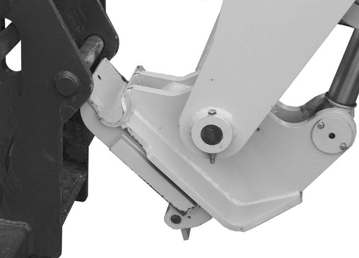
The Telehandler boom nose will accept two types of Mustang attachment devices: 1.) The Quick-attach system, which has a quick-release hookup and locking mechanism for mounting framing and masonry type attachment tools to the boom nose, 2.) the Quick-attach II system, which has a quick-release locking mechanism that uses a single lock lever control for attaching and detaching material handling type attachment tools.
Quick-attach ™ System Attaching Detail
Attaching - Using Quick-attach System
To pick up an attachment tool, proceed as follows:
1.Raise the boom slightly and extend it 2 or 3 feet (600-900 mm) for better visibility. Tilt the tool carrier forward.
2.Align the tool carrier squarely with the back of the attachment tool.
3.Slowly extend the tool carrier and lower the hooks under the attachment tool hookup bar.
4.Roll the tool carrier back so that the lock plate engages the attachment tool. This secures the attachment tool to the Quick-attach tool carrier.
5.For an attachment tool with auxiliary hydraulics, connect hoses to the quick-connect connectors on the boom nose.
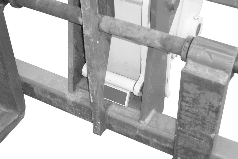
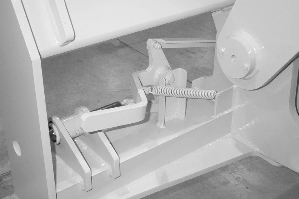
Detaching - Using Quick-attach System
To detach the attachment tool, proceed as follows:
1.Raise the boom slightly and extend it 2 or 3 feet (600-900 mm) for better visibility. Lower the boom until the attachment tool is approximately 12” (0.3 m) off the ground.
2.Roll back the carrier as far as it will go. When the carrier is rolled back completely, perform the MANDATORYSAFETYSHUTDOWN PROCEDURE (Safety chapter).
3.With the engine off, leave the operator’s station and manually raise the lock spring and flip the lock plate up and outward at least 180°, so that it is in position to re-lock onto the next attachment tool.
4.Tilt the tool carrier forward to allow the attachment tool to roll out, then lower the boom so that the hook ears clear the hookup bar on the attachment tool.
NOTE: One side of the lock plate has a bright red decal to indicate the unlocked position.
5.If the attachment tool has auxiliary hydraulics, disconnect the hoses from the quick-disconnects on the boom nose.
6.Start the engine and roll the tool carrier forward. Slowly back the machine until the attachment tool is free from the boom nose.
Quick-attach
™ II System
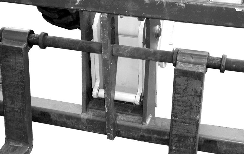
Attaching - Using Manual Quick-attach II System
To pick up a bucket or material handling carriage tool, proceed as follows:
1.Rotate the lock lever completely to the left (counter-clockwise, as viewed from the operator’s station) to fully retract the lock pins.
2.Raise the boom slightly and extend it 2 or 3 feet (600-900 mm) for better visibility. Tilt the tool carrier forward.
3.Align the tool carrier squarely with the back of the attachment tool.
4.Slowly extend the tool carrier and tilt it forward until the support pins on each side are in-line with and slightly below the hookup ears on the back side of the attachment tool.
5.Slowly drive the machine forward, and, at the same time, roll the tool carrier back to engage the hookup ears on the attachment tool. Also, establish proper alignment of the carrier lock pins to the attachment tool.
6.Stop forward travel when the hookup ears are engaged, but continue to roll the tool carrier back to pick the attachment tool off the ground. When the tool carrier is rolled back completely, perform the MANDATORYSAFETYSHUTDOWN PROCEDURE (Safety chapter).
7.With the engine off, leave the operator’s station, and swing the lock lever completely to the right (clockwise, as viewed from the operator’s station) to fully engage the lock pins.
Warning
To prevent unexpected and undesired attachment tool release from the boom carrier, be sure to properly secure the quick-release lock pins by rotating the lock lever all the way to the right or inside.
Modifications, alterations to, or use of attachment tools not authorized by Mustang Manufacturing Company can void the warranty and cause machine damage, and may result in serious personal injury or death.
Detaching - Using Manual Quickattach ™ II System
To detach the attachment tool, proceed as follows:
1.Raise the boom slightly and extend it 2 or 3 feet (600-900 mm) for better visibility. Lower the boom until the attachment tool is approximately 12” (0.3 m) off the ground.
2.Roll back the tool carrier as far as it will go. When the tool carrier is rolled back completely, perform the MANDATORYSAFETYSHUTDOWN PROCEDURE (Safety chapter).
3.With the engine off, leave the operator’s station, and rotate the lock lever completely to the left (counter-clockwise, as viewed from the operator’s station) to fully retract the lock pins.
4.If the attachment tool has auxiliary hydraulics, disconnect the hoses from the quick-connects on the boom nose.
5.Start the engine and tilt the tool carrier forward. Slowly back the machine until the attachment tool is free from the boom carrier.
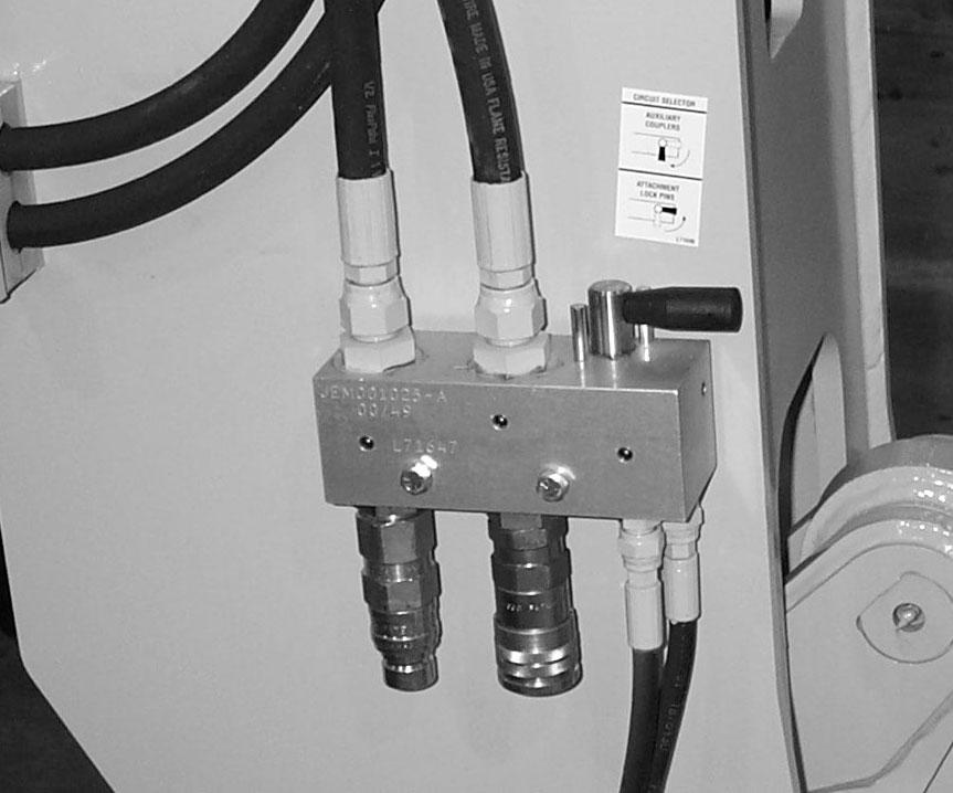
Attaching - Using Hydraulic Actuated Quick-attach ™ II System
1.With the engine off, leave the operator’s station, and turn the circuit selector handle on the end of the boom 1/4 turn counter-clockwise to the attachment lock pins position.
2.Raise the boom slightly and extend it 2 or 3 feet (600-900 mm) for better visibility and tilt the tool carrier forward.
3.Align the tool carrier squarely with the back of the attachment tool.
4.Slowly extend the tool carrier and tilt it forward until the support pins on each side are in-line with and slightly below the hookup ears on the back side of the attachment tool.
5.Slowly drive the machine forward, and, at the same time, press and hold the lower blue auxiliary hydraulic button to retract the attachment lock pins. Roll the tool carrier back to engage the hookup ears on the attachment tool.
6.Stop forward travel when the hookup ears are engaged, but continue to roll the tool carrier back to pick the attachment tool off the ground. When the tool carrier is rolled back completely, release the lower blue auxiliary hydraulic button and press the upper blue auxiliary hydraulic button to engage the attachment lock pins. Perform the MANDATORYSAFETYSHUTDOWN PROCEDURE (Safety chapter).
7.With the engine off, leave the operator’s station, and turn the circuit selector handle on the end of the boom 1/4 turn clockwise to the Auxiliary Couplers position.
8.For an attachment tool with auxiliary hydraulics, connect the hoses to the quick-connect connectors on the boom nose.
Warning
To prevent unexpected and undesired attachment tool release from the Quick-attach II, be sure to turn the Circuit Selector Handle to the Auxiliary Couplers position after the lock pins are engaged to the attachment tool.
Modifications, alterations to, or use of attachment tools not authorized by Mustang Manufacturing Company can void the warranty and cause machine damage, and may result in serious personal injury or death.
Detaching - Using Hydraulic Actuated Quick-attach ™ II System
To detach the attachment tool, proceed as follows:
1.With the engine off, leave the operator’s station, and, if the attachment tool has auxiliary hydraulics, disconnect the hoses from the quick-connects on the boom nose .
2.Turn the circuit selector handle on the end of the boom 1/4 turn counter-clockwise to the Attachment Lock Pins position.
3.While sitting in the operator’s seat, start the engine and raise the boom slightly and extend it 2 or 3 feet (600-900 mm) for better visibility. Lower the boom until the attachment tool is approximately 12” (0.3 m) off the ground.
4.Press and hold the lower blue auxiliary hydraulic button to retract the attachment lock pins, tilt the tool carrier forward. Slowly back the machine until the attachment tool is free from the tool carrier. Release the lower blue button.
SELF-LEVELING
The machine has a hydraulic self-leveling feature. This feature is designed to keep the attachment tool level while the boom is being raised.
Generalmachine Operation
Warning
Exhaust fumes can kill. Ensure proper ventilation when starting indoors or in enclosed areas.
Use proper grab handles, NOT the steering wheel or control levers as handholds when mounting or dismounting.
NEVER operate the machine with safety guards or covers removed.
Over-inflated tires can explode and cause injury or death. Tire repairs MUST be made only by authorized personnel using proper tools and equipment.
Check the Telehandler to make sure all systems are in good operating condition. Perform the following steps before starting the machine for the first time each day.
1.Check the engine oil, coolant, transmission oil and hydraulic oil levels.
2.Be sure weekly lubrication has been done.
3.Visually inspect for leaks, broken or malfunctioning parts. Be sure all caps, covers and safety shields are in place.
4.Check tires for cuts, bulges, nails, correct pressure, loose wheel nuts, etc.
5.Inspect the work area. Be sure you know where you will make load pickups, lifts, and turns. Look over the terrain of the jobsite for holes, obstacles, slippery surfaces, soft or deep mud.
6.Check clearances of ramps, doorways and passage ways. Check overhead clearances if you will travel and place loads near power or telephone lines.
If the machine is found to be in need of repair or in any way unsafe, or contributes to an unsafe condition, the matter shall be reported immediately to the user’s designated authority. The machine should NOTbe operated until it has been restored to a safe operating condition.
Operate the travel controls gradually and smoothly when starting, stopping, turning and reversing the directions directions.
Grade and Slope Precautions
The Telehandler complies with industry stability tests requirements and is stable when properly operated. However, improper operation, faulty maintenance, or poor housekeeping may contribute to a condition of instability and defeat the purpose of the standard.
The amount of forward and rearward tilt to be used is governed by the application. Although use of maximum rearward tilt is allowable under certain conditions, such as traveling with the load fully lowered, the stability of the machine, as determined by the industry standard tests, does not encompass consideration for excessive tilt at high elevations, or the handling of offcenter loads.
Handle only loads within the capacity limits of the machine, and which are stable and safely arranged. When attachments are used, extra care should be taken in securing, manipulating, positioning and transporting the load.
Grade Limits
NOTE: Grade limits are based on ANSI/ITSDF standard B56.6-2005.
The telehandler meets or exceeds the safety standard (ANSI/ITSDF B56.6) stability limits for rough terrain forklifts. The stability tipping limits cover specific, controlled test conditions, which are extremes, and which are not intended to be achieved during normal work site operations. The following specifications are provided only as information to the operator, and must not be used as a guideline for operating the telehandler. For safe operation, always follow the instructions and warnings provided in this manual.
1.DO NOTplace or retrieve loads on a up or down slope or grade that exceeds 7% or 4° grade.
2.DO NOTtravel up or down a grade or slope that exceeds 22% or 12° grade while loaded.
3.DO NOTplace or retrieve loads on a side hill with a slope or grade that exceeds 12% or 7° grade. Regardless of the terrain or position of the wheels, the FRAME MUSTBE LEVEL, as indicated by the frame angle indicator on the ROPS crossmember.
4.DO NOTtravel across a side hill that exceeds 18% or 10° grade. Regardless of the terrain or position of the wheels, the FRAME MUSTBE LEVEL, as indicated by the frame angle indicator on the ROPS crossmember. The attachment tool MUST be maintained at the “carry” position, with the boom fully retracted, and attachment tool at minimum ground clearance.
When ascending or descending grades in excess of 5% or 3o, the machine should be driven with the load upgrade. An unloaded machine should be operated on all downgrades with the load handling attachment tool downgrade, tilted back if applicable, and raised only as far as necessary to clear the road surface. Avoid turning if possible and use extreme caution on grades, ramps or inclines. Normally travel straight up and down.
Warning
DO NOT level the frame with the boom raised or extended. Level the frame only while stopped, with the boom fully retracted, and the attachment tool raised just enough to clear the ground.
Traffic Flow Patterns
For safety, know and understand the traffic flow patterns of your jobsite and the Telehandler hand signals. Use signal persons and make sure you can see the signal person and acknowledge the signals given.
Safety Hand Signals
The backup alarm automatically sounds when the travel lever is in Reverse. Care should be taken when down shifting or reversing because damage to the transmission can occur if shifting is forced or attempted while traveling.
When ramps must be used in transporting loads with the machine, the following shall be the minimum widths for safe travel:
Compacted dirt, gravel, etc. - 12 ft. (3.6 m) Woodboard, concrete, etc. - 10 ft. (3 m)
Permanent aisles, roadways, passageways, floors and ramps should be marked or defined in some fashion. Permanent or temporary protrusion of loads, equipment, material and construction facilities into the usual operating area should be guarded, clearly and distinctively marked, or clearly visible.
Maintain a safe distance from the edge of ramps, platforms and other similar working surfaces.
Controlled lighting of adequate intensity should be provided in operating areas. Where operating conditions indicate, the operator/user is responsible for having the machine equipped with lights.
Provision should be made to prevent trucks, semi-trailers and railroad cars from being moved during loading and unloading. Wheel stops, parking brakes, or other positive means should be used to prevent movement during loading and unloading.
DO NOTmove railroad cars or trailers with the Telehandler.
DO NOTuse the boom and attachment for leverage to push the machine out of mud.
IMPORTANT: DO NOT lower boom at high engine speed when attachment tool is at maximum rearward tilt. Damage to slave cylinders may result.
Generalload Handling
NEVER attempt to work controls except from the operator’s seat. NEVER jerk or use fast movements. Avoid sudden stops, starts and changes in direction.
Operation of the hydraulic system depends on engine speed and the distance the controls are moved. When operating these controls it is important to develop a technique called “feathering.” Feathering the control means starting the desired motion by moving the control a small amount away from neutral. Then, after movement has started, the control can be eased to full movement. Use the same feathering technique to stop the motion.
Warning
Excessive speed can be hazardous. ALWAYS exercise caution and good judgement while operating the machine.
The Mandatory Work Platform Safety Rules must be adhered to at all times while elevating personnel.
ALWAYS maintain a safe distance from electric power lines and avoid contact with any electrically charged conductor or gas line. It is not necessary to make direct contact with a power line for power to ground through the structure of the machine. Keep the boom and load at least 10 ft. (3 m) from all power lines. Accidental contact or rupture can result in electrocution or an explosion. Contact the North American One-Call Referral System at (888) 258-0808 for the local “Digger’s Hotline” number or proper local authorities for utility line locations BEFORE starting to dig!
Keep all body parts inside the operator’s station while operating the machine. BE SURE of clearance for the attachment tool when turning, working around buildings, etc.
Turning corners too fast can tip the machine, or cause a load to tip off the attachment. Sudden slowing or stopping of the machine may cause the load to fall off the attachment tool.
Be certain you can control both speed and direction before moving. Always place the machine in neutral and set the parking brake before raising or extending the boom. NEVER drive the machine up to someone standing in front of the load.
NEVER leave the operator’s station without first lowering the attachment tool to the ground. Set the parking brake, place controls in neutral, shut off engine and remove the key. AVOID parking the machine on a slope, but if necessary, park across the slope and block the tires.
Distance Load Is Extended
Load Capacity and Reach
The machine has flip-charts in the operator’s station that provide, at a glance, the capacity limits at various positions of attachment tool extension and elevation. A set of the load zone charts is reproduced at the end of this manual for reference.
Atypical load zone chart is shown on this page. The scale on the left indicates height in feet above the ground level. The scale on the bottom shows the distance in feet from the front of the machine. The arc lines noted by the numbers “1” through “5” correspond with the position extension markers on the operator side of the intermediate boom section.
The following example illustrates proper use of the load zone charts for the Telehandler:
Example: The operator, using a standard carriage attachment tool without outriggers, wants to raise a 3000 lb. load 20 feet high, and can only get to within 15 feet of the load placement point. Can it be done within the capacity of the machine?
Analysis: See “Typical Load Zone Chart” above.
Projecting up from the 15-foot reach mark on the horizontal axis to intersect a line through the 20-foot height mark on the vertical axis shows that up to a 4000 lb. load can be placed in that zone.
During placement, the operator should observe when the arc reference number “4” on the boom is visible and stop. The operator knows the maximum safe distance of extension with the 3000 lb. load has been reached.
Warning
NEVER exceed the rated operating capacity of the Telehandler as shown on the load zone charts.