10 minute read
7.21.9 CDC parameters – Reset


Preconditions
☑ Engine is stopped and starting disabled.
Note: Failure to reset drift compensation (CDC parameters) will void the emissions certification.
Resetting CDC parameters with DiaSys®
u (→ Dialog system DiaSys® E531920/..).
Resetting CDC parameters without DiaSys®
u If no DiaSys® is available, contact Service.
8 Appendix A
8.1 Abbreviations
Abbreviation Meaning Explanation
ADEC Advanced Diesel Engine Control Engine governor AL Alarm Alarm (general) ANSI American National Standards Institute Governing body for US American standards ETC Exhaust turbocharger BR Baureihe (Series) BV Betriebsstoffvorschrift Fluids and Lubricants Specifications, MTU Publication No. A01061/.. CAN Controller Area Network Data bus system, bus standard CDC Calibration Drift Compensation Setting for drift correction with DiaSys in engine governor
CPP Controllable Pitch Propeller DILA Diagnostic lamp on EIM DIN Deutsches Institut für Normung e. V. German Standardization Organization, at the same time identifier of German standards ("Deutsche Industrie-Norm")
DIS Display unit DL Default Lost Display panel Alarm: Default CAN bus failure
ECS Engine Control System ECU Engine Control Unit EDM Engine Data Module EIM Engine Interface Module EMU Engine Monitoring Unit SPC Spare Parts Catalog FPP Fixed Pitch Propeller GCU Gear Control Unit GMU Gear Monitoring Unit HAT Harbor Acceptance Test HI High HIHI High High HT High Temperature ICFN ISO - Continuous rating - Fuel stop power - Net IDM Interface Data Module IIG Initial Injector Equalization Engine management system Engine governor Memory module for engine data Interface to engine monitoring system
Alarm: Measured value exceeds 1st maximum limit Alarm: Measured value exceeds 2nd maximum limit
Power specification in accordance with DIN-ISO 3046-7 Memory module for interface data Entering of injector code with DiaSys in engine governor
IMO International Maritime Organization ISO International Organization for Standardization KGS Kraftgegenseite International umbrella organization for all national standardization institutes Engine free end in accordance with DIN ISO 1204
Abbreviation Meaning
KS Kraftseite LCD Liquid Crystal Display, Liquid Crystal Device LCU Local Control Unit LED Light Emitting Diode LMU Local Monitoring Unit LO Low LOLO Low Low LOP Local Operating Panel LOS Local Operating Station MCS Monitoring and Control System MG Message MPU Microprocessor Unit, Microprocessing Unit Explanation
Engine driving end in accordance with DIN ISO 1204
LOP subassembly
LOP subassembly Alarm: Measured value lower than 1st minimum limit Alarm: Measured value lower than 2nd minimum limit Control console, control panel
Microprocessor (unit)
TDC Top Dead Center P-xyz Pressure-xyz PAN Panel Pressure measuring point xyz Operating panel
PCU Propeller Control Unit PIM Peripheral Interface Module RCS Remote Control System RL Redundancy Lost Alarm: Redundant CAN bus failure SAE Society of Automotive Engineers U.S. standardization organization SAT Sea Acceptance Test SD Sensor Defect Alarm: Sensor failure SDAF Shut Down Air Flaps Emergency-air shutoff flap(s) SILA Fuse lamp on EIM SOLAS International Convention for the Safety of Life at Sea SS Safety System Indicated alarm is initiated by the safety system SSK Emergency-air shutoff flap(s) T-xyz Temperature-xyz TD Transmitter Deviation Temperature measuring point xyz Alarm: Sensor comparison fault
BDC Bottom Dead Center VS Voith Schneider Voith-Schneider drive
WJ Water Jet Water jet drive
TC Tool Catalog ZKP Zugehörigkeit-Kategorie-Parameter Numbering plan for ADEC ECU signals
8.2 MTU contact persons/service partners
Our worldwide sales network with its subsidiaries, sales offices, representatives and customer service centers ensures fast and direct support on site and the high availability of our products.
Local support
Experienced and qualified specialists place their knowledge and expertise at your disposal. For locally available support, go to the MTU Internet site: http://www.mtu-online.com
24h hotline
With our 24h hotline and the outstanding flexibility of our service staff, we are always ready to assist you – either during operation, for preventive maintenance, corrective work in case of malfunction or changed operating conditions, or for spare parts supply. Your contact person in our Customer Assistance Center: E-mail: info@mtu-online.com
Tel.: +49 7541 9077777
Fax: +49 7541 9077778 Asia/Pacific: +65 6100 2688 North and Latin America: +1 248 560 8000
Spare parts service
Fast, simple and correct identification of spare parts for your drive system or vehicle fleet. The right spare part at the right time at the right place. With this aim in mind, we can call on a globally networked spares logistics system, a central warehouse at headquarters and on-site stores at our subsidiary companies, agencies and service workshops. Your contact at Headquarters: E-mail: spare.parts@mtu-online.com Tel.: +49 7541 908555
Fax: +49 7541 908121
9 Appendix B
9.1 Special Tools
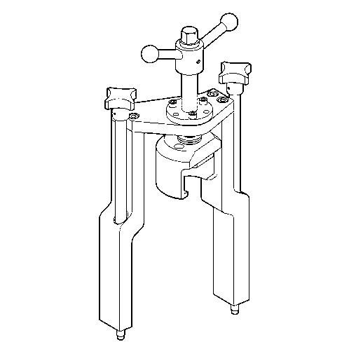
Barring device
Part No.: F6555766 Qty.: Used in: 1 7.1.1 Engine – Barring manually (→ Page 132)
Feeler gauge
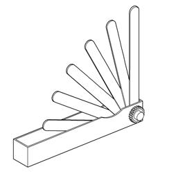
Part No.: Y20010128 Qty.: Used in: 1 7.3.2 Valve clearance – Check and adjustment (→ Page 140)
Filter wrench
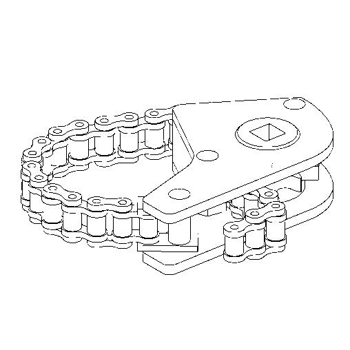
Part No.: F30379104 Qty.: Used in: 1 7.6.2 Additional fuel filter – Replacement (→ Page 153)
Qty.: Used in: 1 7.6.3 Fuel filter – Replacement (→ Page 154)
Qty.: Used in: 7.13.2 Engine oil filter – Replacement (→ Page 183) Qty.: Used in: 1 7.13.3 Centrifugal oil filter – Cleaning and filter sleeve replacement (→ Page 185)
Qty.: Used in: 1 7.14.8 Engine coolant filter – Replacement (→ Page 201)
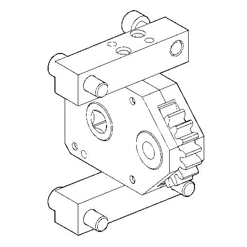
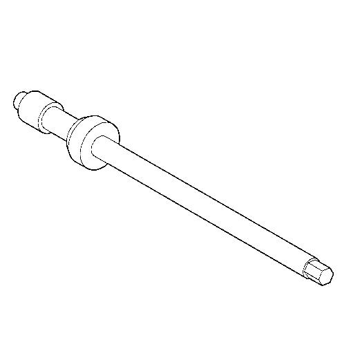
Installation/removal tool
Part No.: F6789889 Qty.: Used in: 1 7.5.2 Injector – Removal and installation (→ Page 147)
Milling cutter
Part No.: F30452739 Qty.: Used in: 1 7.5.2 Injector – Removal and installation (→ Page 147)
MTU test kit
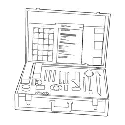
Part No.: 5605892099/00 Qty.: Used in: 1 7.12.3 Engine oil – Sample extraction and analysis (→ Page 179)
Qty.: Used in: 1 7.14.7 Engine coolant – Sample extraction and analysis (→ Page 200)
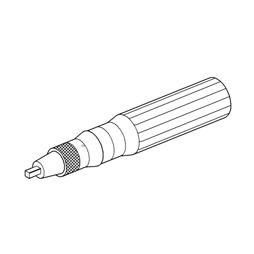
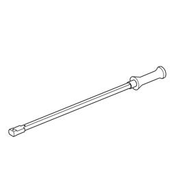
Ratchet
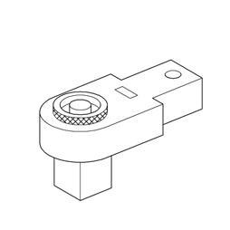
Part No.: F30027340 Qty.: Used in: 1 7.5.2 Injector – Removal and installation (→ Page 147)
Ratchet
Part No.: F30027341 Qty.: Used in: 1 7.5.2 Injector – Removal and installation (→ Page 147)
Ratchet

Part No.: F30027339 Qty.: Used in: 1 7.19.5 Coalescer filter element – Replacement (→ Page 213)
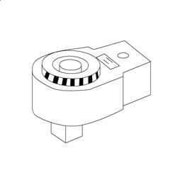
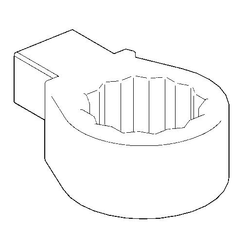
Ratchet adapter
Part No.: F30027340 Qty.: Used in: 1 7.6.7 Fuel prefilter with water separator – Filter element replacement (→ Page 161)
Qty.: Used in: 1 7.7.1 Compressor wheel – Cleaning (→ Page 163)
Ratchet adapter
Part No.: F30027341 Qty.: Used in: 1 7.12.2 Engine oil – Change (→ Page 177)
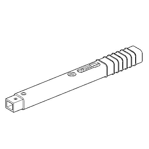
Ratchet with extension
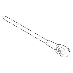
Part No.: F30006212 Qty.: Used in: 1 7.1.1 Engine – Barring manually (→ Page 132)
Rigid endoscope
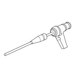
Part No.: Y20097353 Qty.: Used in: 1 7.2.1 Cylinder liner – Endoscopic examination (→ Page 135)
Socket wrench, 24 mm
Part No.: F30039526 Qty.: Used in: 1 7.3.2 Valve clearance – Check and adjustment (→ Page 140)
Steam jet cleaner
Part No.: Qty.: Used in: 1 4.14 Plant – Cleaning (→ Page 98)
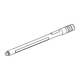
Torque wrench, 0.5-5 Nm
Part No.: 0015384230 Qty.: Used in: 1 7.5.2 Injector – Removal and installation (→ Page 147)
Torque wrench, 10-60 Nm
Part No.: F30510423 Qty.: Used in: 1 7.6.7 Fuel prefilter with water separator – Filter element replacement (→ Page 161)
Torque wrench, 10-60 Nm
Part No.: F30452769 Qty.: Used in: 1 7.7.1 Compressor wheel – Cleaning (→ Page 163)
Torque wrench, 10-60 Nm
Part No.: F30452769 Qty.: Used in: 1 7.5.2 Injector – Removal and installation (→ Page 147)
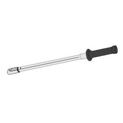
Torque wrench, 40-200 Nm
Part No.: F30027337 Qty.: Used in: 1 7.12.2 Engine oil – Change (→ Page 177)
Torque wrench, 6-50 Nm

Part No.: F30027336 Qty.: Used in: 1 7.13.3 Centrifugal oil filter – Cleaning and filter sleeve replacement (→ Page 185)
Torque wrench, 6-50 Nm
Part No.: F30027336 Qty.: Used in: 1 7.19.5 Coalescer filter element – Replacement (→ Page 213)
Torque wrench, 60-320 Nm
Part No.: F30047446 Qty.: Used in: 1 7.3.2 Valve clearance – Check and adjustment (→ Page 140)
Torque wrench, 60-320 Nm
Part No.: F30452768 Qty.: Used in: 1 7.5.2 Injector – Removal and installation (→ Page 147)
9.2 Index
Preheating unit 202
Numerics 12V 4000 M53R engine data 72
A Abbreviations 236 Actuators – Overview 52 Additional fuel filter – Replacement 153 ADEC (ECU 7) – Fault messages 105 After stopping the engine 97 Air filter – Removal and installation 173 – Replacement 172
B Battery-charging generator drive – Coupling condition check 206 Bilge pump – Relief bore check 208
C CDC parameters – Reset 235 Centrifugal oil filter – Cleaning 185 Charge-air cooler – Checking condensate drain for water discharge and obstruction 171 Checks – Prior to start-up 89 Coalescer filter element – Replacement 213 Compressor wheel – Cleaning 163 Contact persons 238 Controls 83 Coolant – Change 193 Cylinder – Designation 14 Cylinder head cover – Removal and installation 143 Cylinder liner – Endoscopic examination 135 – Instructions and comments on endoscopic and visual examination 137
D Designations – Engine sides and cylinders 14 Differential pressure gauge – Check 210 Drain and vent points 188 Drift compensation – Reset 235
E ECU 7 – Installation 229 – Removal 229 EMU 7 – Installation 230 – Removal 230 Engine – Barring manually 132 – Barring with starting system 134 – Emergency stop 96 – Main dimensions 80 – Start 86 – Stopping 95 – Wiring check 224 Engine Control Unit ECU 7 – Checking plug connections 226 – Installation 229 – Removal 229 Engine coolant – Change 193 – Draining 194 – Filter replacement 201 – Sample analysis 200 – Sample extraction 200 Engine coolant level – Check 192 Engine coolant – Filling 197 Engine data – 16V 4000 M53R 76 Engine governor ADEC (ECU 7) – Fault messages 105 Engine Interface Module EIM – Removal and installation 231 Engine layout 38 Engine monitoring unit EMU 7 – Plug connection check 227 Engine mounting – Checking securing screws for firm seating 207 Engine oil – Sample extraction and analysis 179 Engine oil – Change 177 Engine oil filter – Replacement 183 Engine oil level – Check 176 Engine sides – Designation 14 Engine wiring – Check 224
Engine wiring harness – Overview 215
F Fault messages – Engine governor ADEC (ECU 7) 105 Filter – Coalescer element – Replacement 213 – Engine coolant – Replacement 201 Filter sleeve – Replacement 185 Firing order 82 Fuel – Treatment system – Switching on 93 – Troubleshooting 104 – treatment system – Shutdown 94 Fuel filter – Replacement 154 Fuel prefilter – Flushing 159 Fuel prefilter – Draining 157 Fuel prefilter with water separator – Filter element replacement 161 Fuel prefilter – Differential pressure gauge – Adjustment 156 – Check 156 Fuel treatment system – Putting into operation 90 – Shutdown 94 – Switching on 93
H Hotline 238 HP pump – Filling with engine oil 144 – Relief bore check 145 HT coolant pump – Relief bore check 199
I Injector – Installation 147 – Removal 147 – Replacement 146 Interface module EIM – Check 228
L Limit switch for start interlock – Check 225
M Maintenance schedule – Maintenance task reference table [QL1] 99 MTU contact persons 238
O Oil indicator filter – Checking 181 Operational checks 87
P Plant – Cleaning 98 Plug connections – Check 228 Product description 15 Pump capacity – Check 212 Putting the engine into operation after extended out-ofservice periods (>3 months) 84 Putting the engine into operation after scheduled out-ofservice-period 85
R Raw water pump – Relief bore check 205
S Safety notices, standards 13 Safety regulations – Consumables 11 – Environmental protection 11 – Fire prevention 11 – Fluids and lubricants 11 – Important provisions 5 – Maintenance work 8 – Organizational requirements 6 – Personnel requirements 6 – Repair work 8 – Safety notices, standards 13 Sensors – Overview 52 Sensors and actuators – Overview 42 Service indicator – Signal ring position check 174 Service partners 238 Spare parts service 238 Starter – Condition check 175 Supplementary fuel filter – Overview 152
T Tasks – After extended out-of-service periods 88 Tasks after extended out-of-service periods (>3 weeks) 88 transport 7 Troubleshooting 101 – Fuel treatment system 104
V Valve clearance – Adjustment 140 – Check 140 Valve gear – Lubrication 139
W Water drain valve – Check 209 Water level probe (3-in-1 rod electrode) – Check 211


