2 minute read
7.21.8 Diagnostic features of EIM


Diagnostic lamp (DILA)
A diagnostic lamp (LED, blue) is integrated in the housing of the Engine Interface Module (EIM). It indicates the operating status of the EIM.
Functions of diagnostic lamp DILA DILA lights Engine Interface Module (EIM) is OK DILA dark EIM supply voltage missing or diagnostic lamp activation is faulty. DILA flashes Hardware or software fault in the Engine Interface Module.
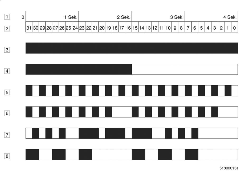
The diagnostic lamp (DILA) signals the following states:
1 Time in seconds 2 Timing: 1/8 s 3 Ready for operation 4 Application loader active 5 External RAM faulty 6 External FLASH faulty 7 No firmware 8 Application crashed
Fuse lamp (SILA)
A second indicator is the fuse lamp. This is also integrated in the housing of the Engine Interface Module. It indicates the status of the fuses. An orange LED is provided to allow diagnosis of a “tripped fuse” fault directly at the unit as it is often difficult to pinpoint a fault in the field without cabling diagrams. This LED is activated by the controller.
Functions of fuse lamp SILA SILA dark Norma operating state. SILA flashes orange One or more fuses have tripped.
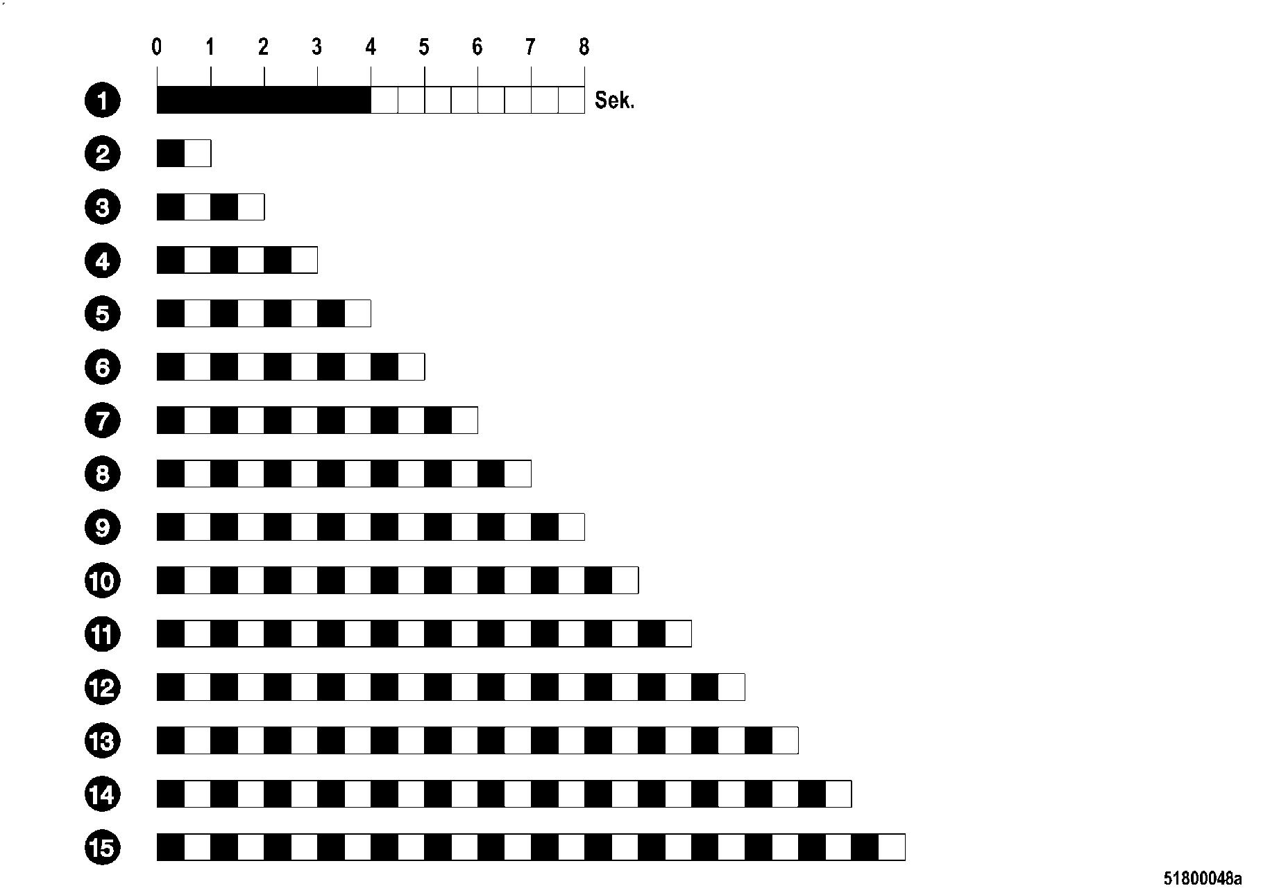
1 Preamble 2 ECU current path failed (S1) 3 MCS current path failed (S2) 4 EMU current path failed (S3) 5 Starter voltage: Terminal 30, 31 not connected and
PR 10.0600.001 has value 1 or 2 (S4)
6 VSP current path failed (S5) 7 SLD current path failed (S6) 8 DDV current path failed (S7) 9 Gear monitoring current path failed (S8) 10 Emergency stop current path failed – 24V internal (S9)
11 ES pushbutton current path failed – 24V external (S10) 12 Key switch current path failed (S11) 13 SDAF 1+2 current path failed (S12) 14 PIM current path failed (S13) 15 Spare current path failed (S14) The failed current paths are signaled consecutively following the preamble (LED on for 4 seconds (1)). There is a pause lasting 4 seconds in between.
Sample flashing sequences
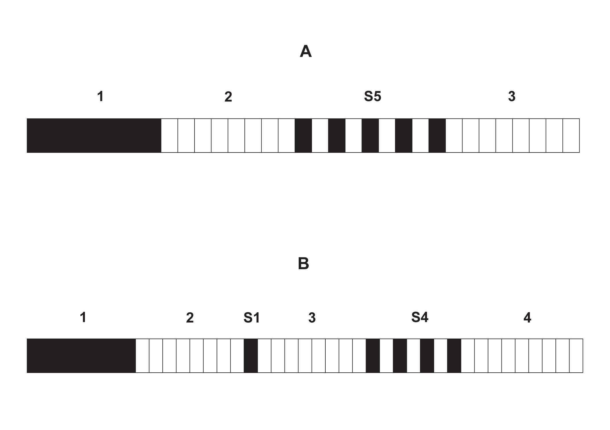
A Fuse S5 failure (1/2 second steps) B Fuse S1 and fuse S4 failure (1/2 second steps)
Note: These bit sequences are transmitted constantly.
Information about the status of the current paths of the EIM is also provided in the CAN message "Status internal power supply".


